Week 3 Challenge : CFD meshing on Turbocharger
Aim:
To create a mesh of different target lengths on a given turbocharger model.
Objectives:
To mesh the components according to the target lengths given
- Blade stage-1 = 1 mm
- Blade stage-2 = 1 mm
- Impeller = 2 mm
- Shaft rotor = 1 mm
- Turbo casing = 5 mm
- Compressor casing = 5 mm
- Inlet casing cover = 5 mm
Procedure:
We have taken the model file into the ansa software
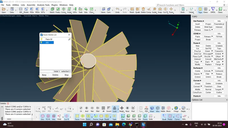
We have checked the model for geometricalerrors and the errors present where corrected using the faces tool in the topo deck and the fill hole tool.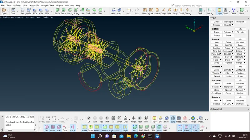
The error correction has been shown below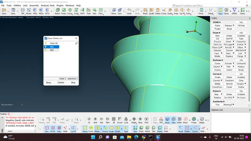
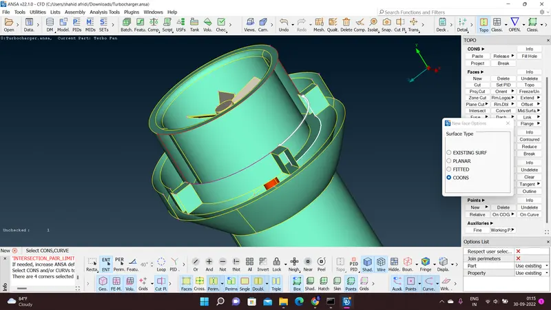
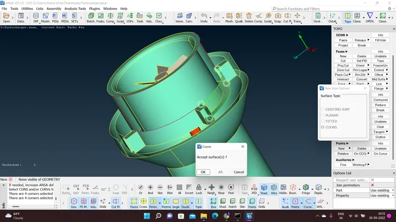
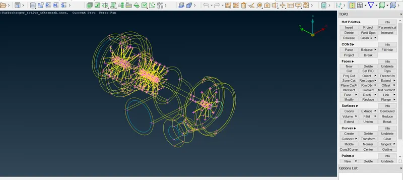
Once after completing the all geometricalerror corrections we will find the wire frame as below.
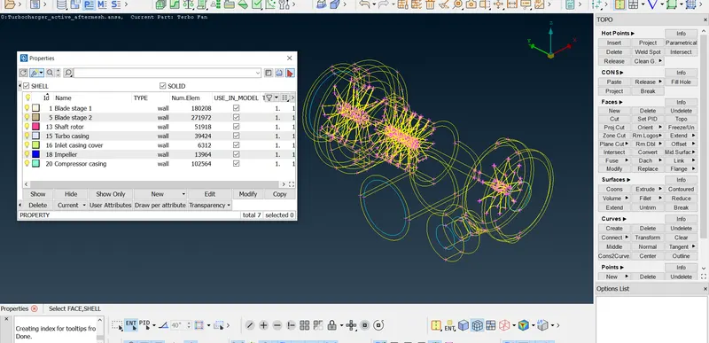
We have to assign the different components of the turbocharger to their respective PID
SURFACE MESHING OF THE COMPONENTS:
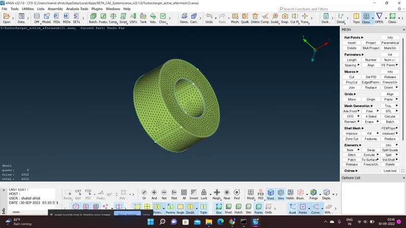
We are to mesh 1mm meshing on three components of the turbocharger. they are
BLADE STAGE-1
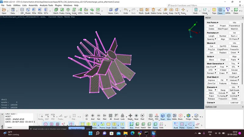
BLADE STAGE-2
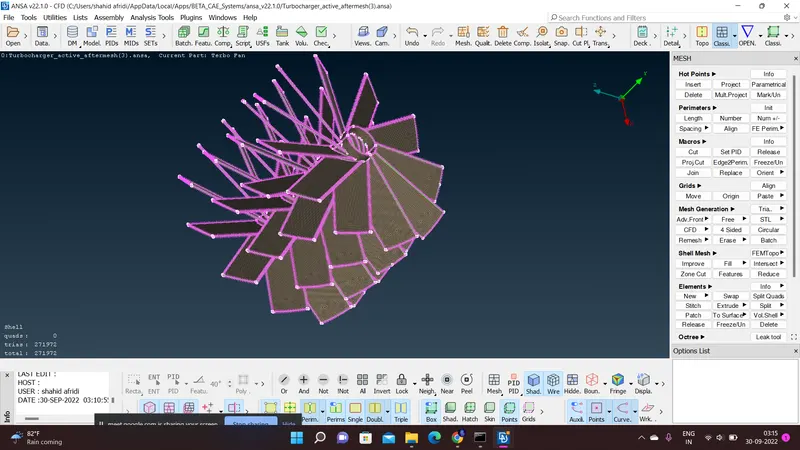
SHAFT ROTOR
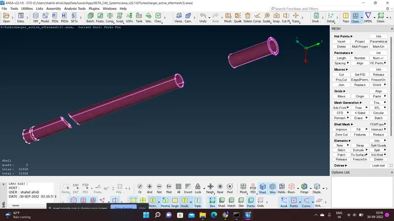
In order to do this we have chosen cfd mesh in the mesh parameters tool and we have given the minimum and maximum total length 0.9 and 1.5mm.
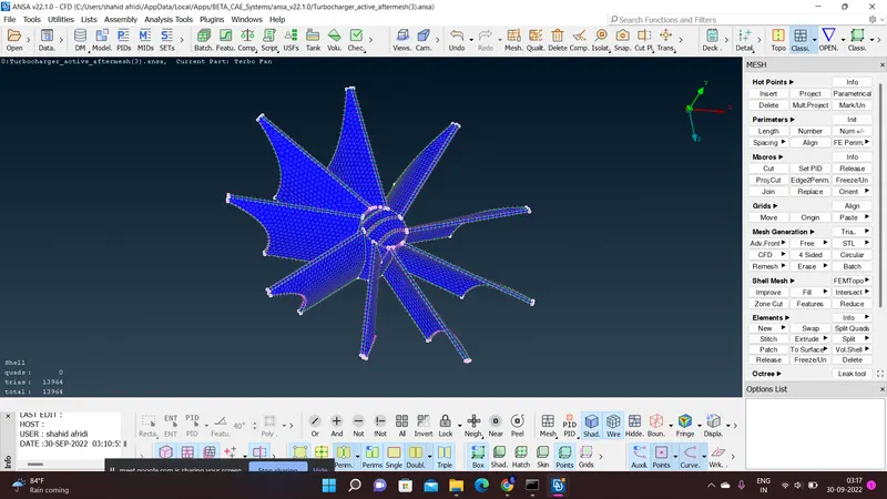
similarly we have to do a 2mm mesh and the impeller model so we have chosen the minimum and maximum target length to be between 1.7 and 2.4mm.
IMPELLER
Likewise we are to make a minimum and maximum total length of 4.7 and 5.6mm for the meshing of components such as
COMPRESSOR CASING
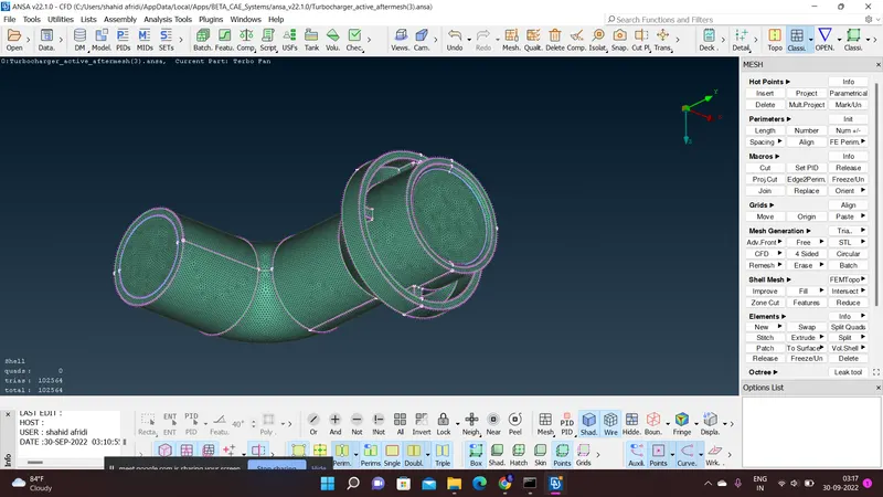
TURBO CASING
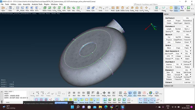
INLET CASING COVER
VOLUME MESHING:
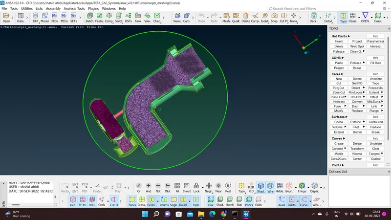
After completing the surface mesh click on the V mesh and the click define,then few errors will be displayed in which choose just the dialog box indicating the internal surface and delete all the errors which shows the external column,once then we will be left with three warning which are stated as undefined parts and type choose unstructure and in the mesh choose tetra cfd. Then we find the status of each unmeshed so remesh then with the help of right click and remesh.The ultimate goal of creating a volumetric mesh is done for the turbocharger of various components and of various total lengths to check the cross section, click cut plane, new, along x and y axis and make a desired point on the model so it will show how the internal volume is meshed.Final image is shown below
Result:
Hence, the meshing process of the given turbo charger model is completed.
File link is attached below,
https://drive.google.com/file/d/1EtldZVpnyrKmEeeTvX84X8Gd65DRnVgi/view?usp=sharing