Week 3 Challenge : CFD meshing on Turbocharger
Aim:
For the given model of a turbocharger, check for the geometrical errors to make appropriate volumes.Create and assign PIDs accordingly. Create surface mesh and use that to create a volumetric mesh.
Objective:
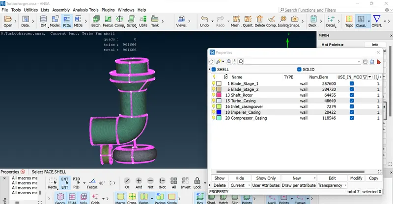
1. Perform surface mesh with the given target lengths as per PIDs.
Blade stage-1 = 1 mm
Blade stage-2 = 1 mm
Impeller = 2 mm
Shaft rotor = 1 mm
Turbo casing = 5 mm
Compressor casing = 5 mm
Inlet casing cover = 5 mm
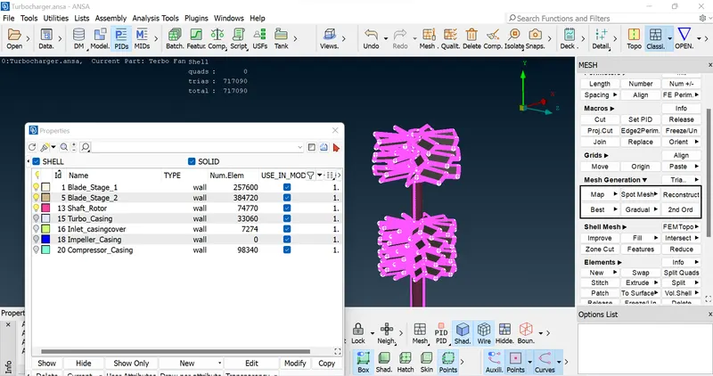
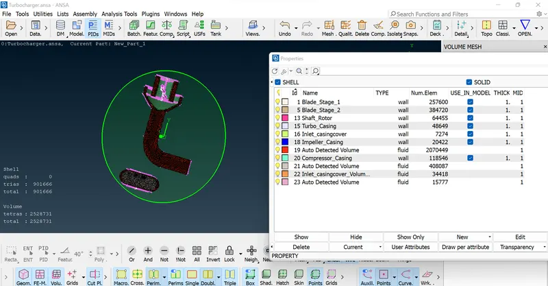
2. Perform Volumetric mesh for the required volumes as shown in the videos.
3. Write a detailed report on your surface meshing & Volume meshing process
- PROCEDURE
1.) GEOMETRY/TOPO CLEANUP
a) Open Turbocharger.ANSA File from the Respective Domain where you have Downloaded it.
(TURBOCHARGER MODEL)
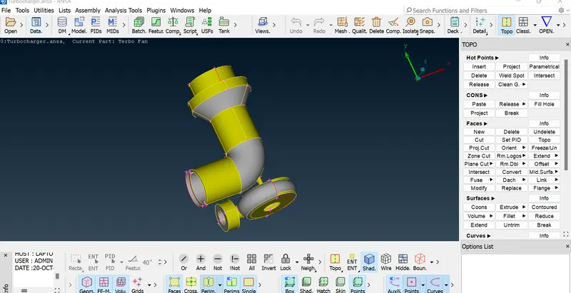
b) Start with the topo clean by doing geometry check to find single and triple cons in the geometry.
select topo under faces and box select the entire model so that any missing cons can be detected and the geometry clean up can be done more accurately.
c) Delete the unecessary overlapping surfaces by using the delete option.
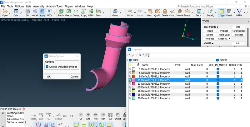
d) Start with fill the surface and clearing the single cons by creating surface where ever required.
e) Use intersect option to delete the surface which has no separate entity, therefore a separate entity is formed when using intersect and can be deleted easily & certain hotpoints are projected so that small surfaces can be created and later can be joined and get the required geometry.
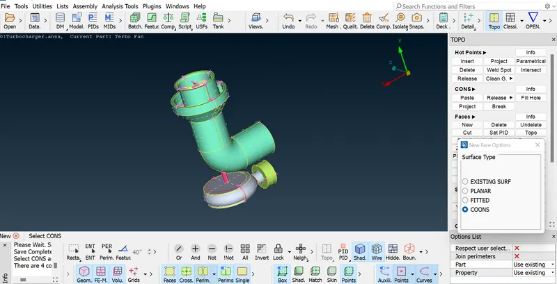
f) Once the single cons are solved for, we can focus now on solving for triple cons which are present at the shaft region, since we need to have a single volume which makes it easier to mesh in the later stage. Delete the overlapping surfaces to reduce them to double cons.
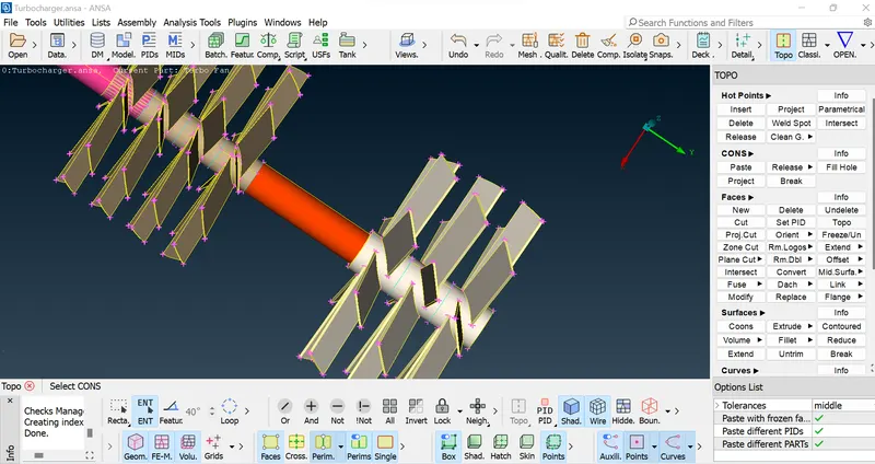
g) Remove all Unnecessary Geometric and Intersection Errors so that we can proceed with Surface Meshing.
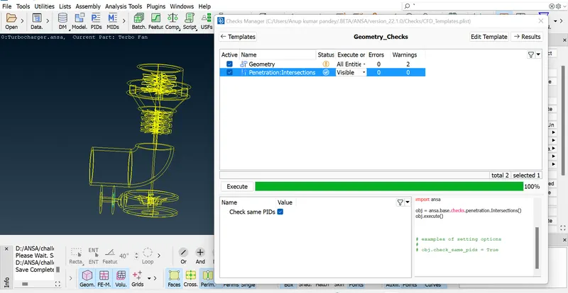
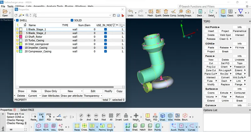
h) Make the Turbocharger a Close Enclosure and Later on Assigning the PID's to its Respective names so that we can mesh the components separately.
2.) SURFACE MESHING
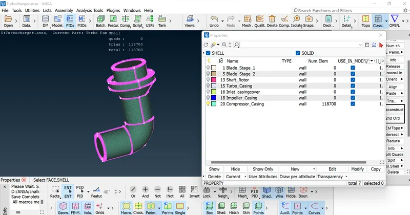
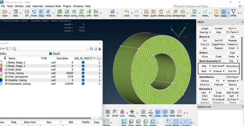
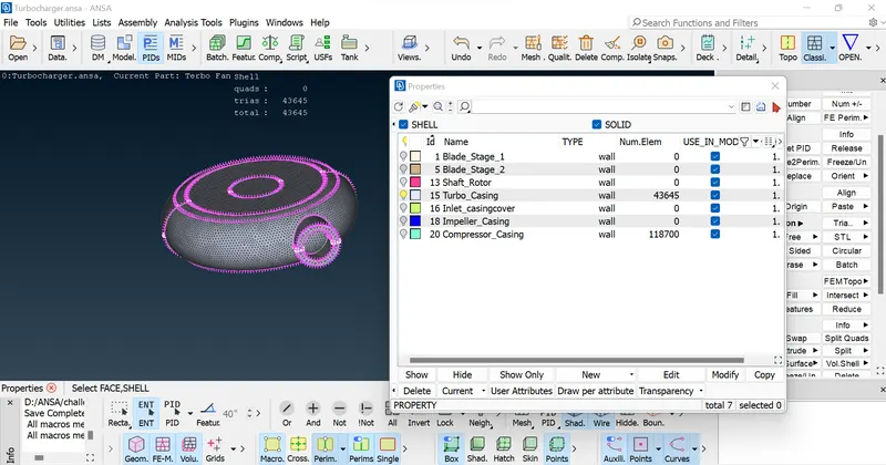
a) We need to Mesh Each & Every Component with respect to given criteria, so purposely Enter the Quality and Mesh parameters for each component.
3.) VOLLUME MESHING
4.) CONCLUSIONS
1. Achieved volumetric mesh of the turbocharger model.
2. Different mesh length size tend to give errors at the contact regions of 2 different mesh length regions, therefore mesh ranges can be given to avoid
erasing of mesh.
3. Volumetric mesh can be achieved only after creating surface mesh successfully, or else the geometry can give fatal errors while volume meshing.
4. Overlapped surface can be deleted using the universal delete option.
5. Unecessary single and triple cons can be removed and editted using different tools such as cons project, topo, release and fine tools
while goemetry clean up.