Week 2 Challenge : Surface meshing on a Pressure valve
Objective :
The objective of this project is to create a Surface meshing on a Pressure valve with element type of tria and mesh the model
with three different target lengths i.e., 1mm, 3 mm and 5 mm by using ANSA.
Introduction :
ANSA is a Computer-aided engineering tool for Finite Element Analysis and CFD Analysis widely used in the automotive industry.
It is developed by BETA CAE Systems. The software is distributed world wide by a number of BETA CAE Systems subsidiaries and
business agents. ANSA maintains the association between CAD geometry and the FE mesh. This means that the FE meshes are better
representations of their geometric parents. Also it is easy to maintain and update any changes in the geometry by simply reworking
the updated area instead of recreating the FE from scratch.
It carries several proprietary algorithms for meshing suitable for both CFD and structural models.
ANSA was initially standing for 'Automatic net generation for structural analysis', but the software has gone beyond that very quickly.
ANSA has broadly six menus which are used to do various activities those are: TOPO MESH, VMESH ,DECK-SOLVER, MORPH ,HBLOCK.
Procedure :
1.) Import the CAD model by Go to file -> open -> browse the location of the CAD model -> select it click on open.
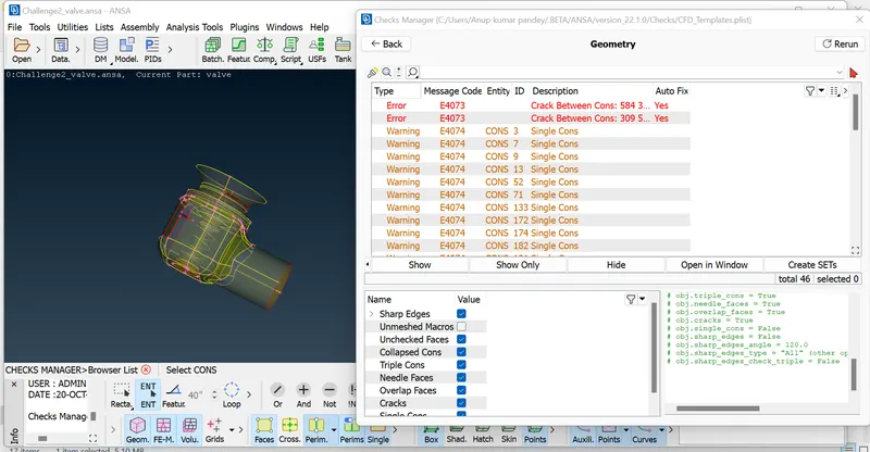
2.) We can see a lot of topological errors ,but before topo clean up letus do geometry check to see all the errors the model,
Geometry check-up is done to check whether there are any errors in the model like Unclosed faces, Super Imposing faces , any
holes or any geometry disorder. etc..To do this operation , go to toolbar -> checks -> geometry -> visible -> execute.
3.) Topo/Geometry cleanup :
a) If you want to see the location of error shown in the geometry check up , you can select pick and select the con to see where it is present
and see the preview of the error(single con) in the model.
b) We will use visibility tools to see the single cons and we have to clear the single cons whereever they present.
c) We will patch all the single cons by creating a new face over there.
d) We will create / patch the surface by using the new under faces .
Here we have 4 options to use under new , they are existing surface ,planar, coons and fitted.We will also use fill holes under cons.
e) We use these different type of algorithms to create face depending upon the applications . So when one fails to create a better surface,
we try with other alternate / algorithm,
In Below Image you will See all Type of Errors.
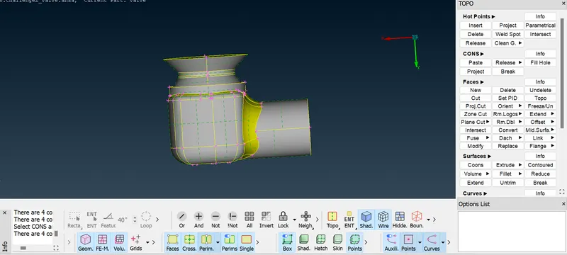
4.) In the similar way we create surfaces wherever there are single cons by using the above algorithms,
The below is the image after patching all the surfaces.
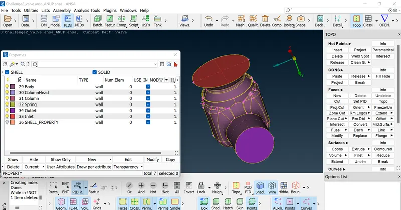
5.) Setting-up of Relevant PIDs by select /click on the PID to apply in the PID manager -> then right click on it -> then click on apply ->
then in the geometry select the cross hatch of the surface you want to assign -> then middle click . In the similar way we have to apply PID's
we have created . To give the PID we select with the different type of selection available to select the exact surface needed.
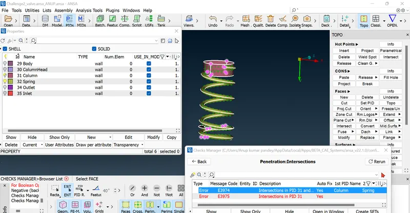
6.) Removing Intersection Errors Between Spring and Column.
7.) Defining the element size/length :
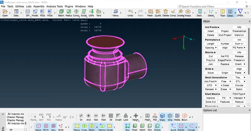
Case-1 :- Target length = 1 mm
Go to mesh utility -> perimeters -> length -> now select perimeters and then-> click left mouse button and drag and select the entire model ->
click middle mouse button -> Enter the element length as 1 mm -> Click middle mouse button.
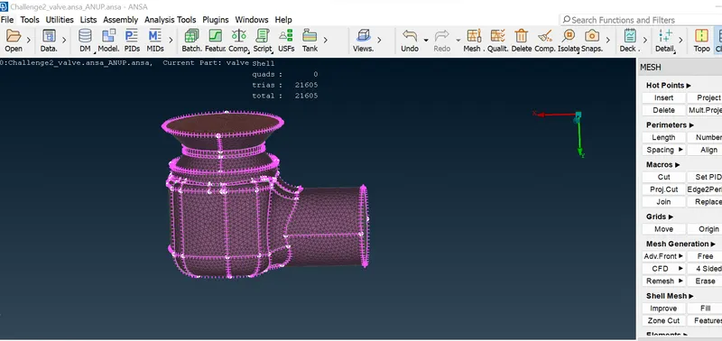
Case-2 :- Target length = 3 mm
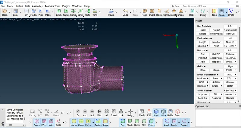
Case-3 :- Target length = 5 mm
Conclusions
1.) Here finally we have surface meshed the given model with three different lengths i.e., 1mm, 3 mm, 5mm .By observing the above results we made the
below conclusions.
2.) We can observe that as the mesh size is increasing there is a derease in the number of elements.
3.) The size of the target length shoud be such that , it should be justify each and every component of our model mainly it should be taken by
considering the smallest component in the Model.
4.) The Mesh quality always depend upon the size of the target length .So if our target length is small , we have small elements ,which eventually
increases the number of elements ,then we will have a good quality mesh such that our geometry is very well captured and surface quality is very good.
5.) We can also observe as we have selected tria elements in all the three cases we see quad elements are 0 in the model we meshed.
Learning Outcome:
Here we also found that smaller element captures curvature of geometry more accurately.