Week 3 Challenge : CFD meshing on Turbocharger
CFD meshing on turbocharger
Aim:
For the given model of a turbocharger, check for the geometrical errors to make appropriate volumes. Create and assign PIDs accordingly. Create surface mesh and use that to create a volumetric mesh.
Objective:
- to Perform surface mesh with the given target lengths as per PIDs.
Blade stage-1 = 1 mm
Blade stage-2 = 1 mm
Impeller = 2 mm
Shaft rotor = 1 mm
Turbo casing = 5 mm
Compressor casing = 5 mm
Inlet casing cover = 5 mm
- Perform Volumetric mesh for the required volumes as shown in the videos.
- Write a detailed report on your surface meshing & Volume meshing process.
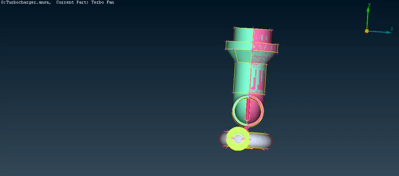
Turbocharger Model:
Procedure:
- Topo/ geometry clean-up:
- Upload the ANSA file using the open option under file drop down.
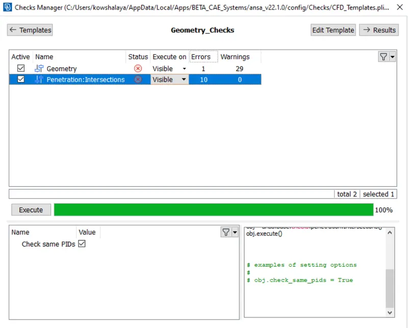
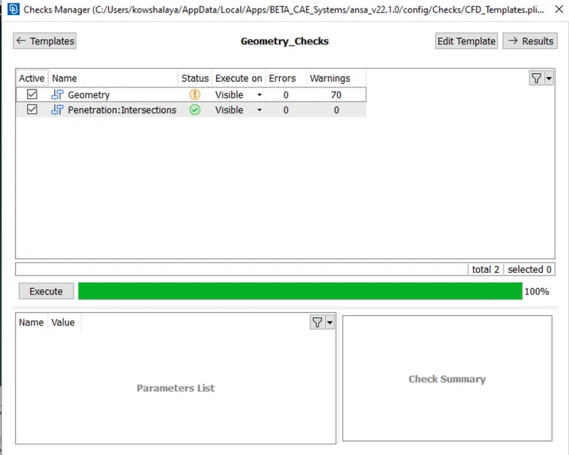
- Start with the topo clean by doing geometry check, check>>check’s manager>>geometry checkup to find single and triple cons in the geometry. select topo under faces and box select the entire model so that any missing cons can be detected and the geometry clean up can be done more accurately.
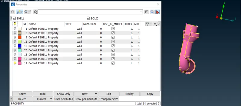
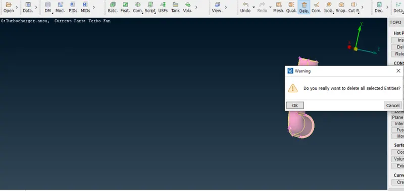
- Delete the unnecessary overlapping surfaces by using the universal delete option, by using the PID mode and PID properties option we can easily identify the overlapping surfaces.
d.Start with fill the surface and clearing the single cons by creating surface where ever required. Her by creating a a hot point we have transformed the surface copy. By using option transform>>copy>>select the entities>>symmetry>>select the 3 hot points and click finsh the uncovered surface will be transformed
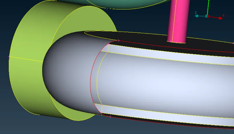
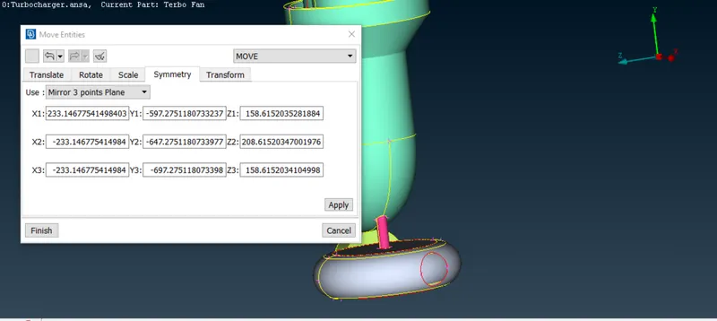
Using fill hole option we can cover the hole in turbine case
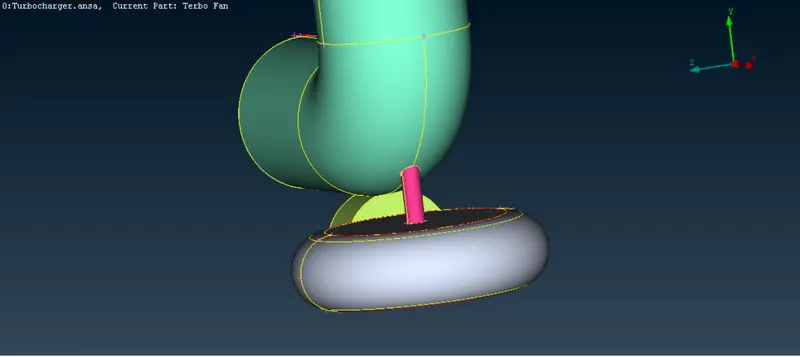
e.Here there is an unnecessary part so we are going to project it to surface
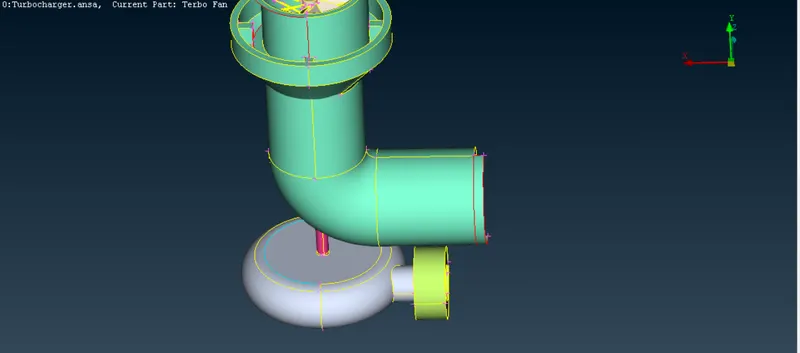
By using the project option to the surfaces and we can delete unnecessary objects
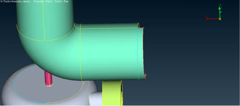
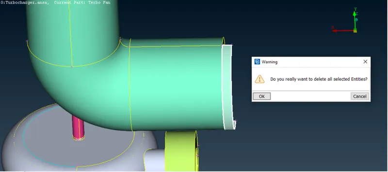
Like this we are going to solve the errors like intersections and overlapping surfaces
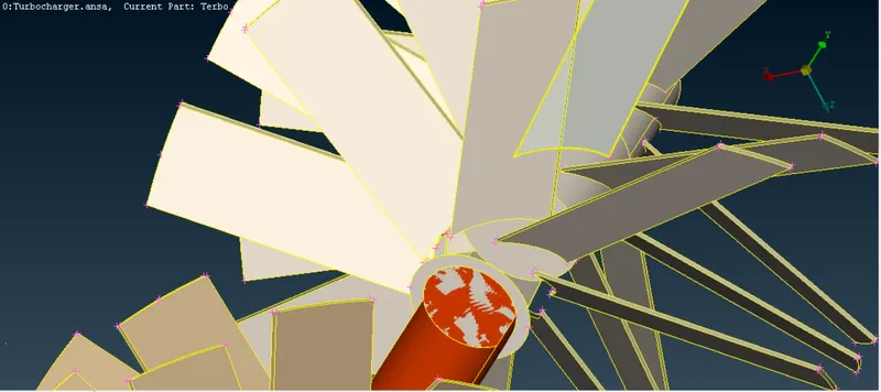
Here we are going to delete the surface and we are going to project the shaft so the overlapping will be not there so we can complete volumetric mesh.
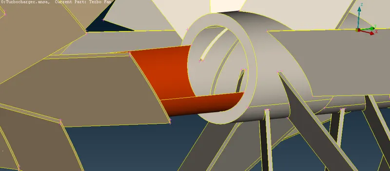
Here we have deleted the center block of the blade stage 2 and we have projected it to the shaft surface. Like this we have to do in this whole shaft avoiding the overlapping surfaces and intersections.
After completing it we should check the geometry, if there are no errors, we can move to surface meshing
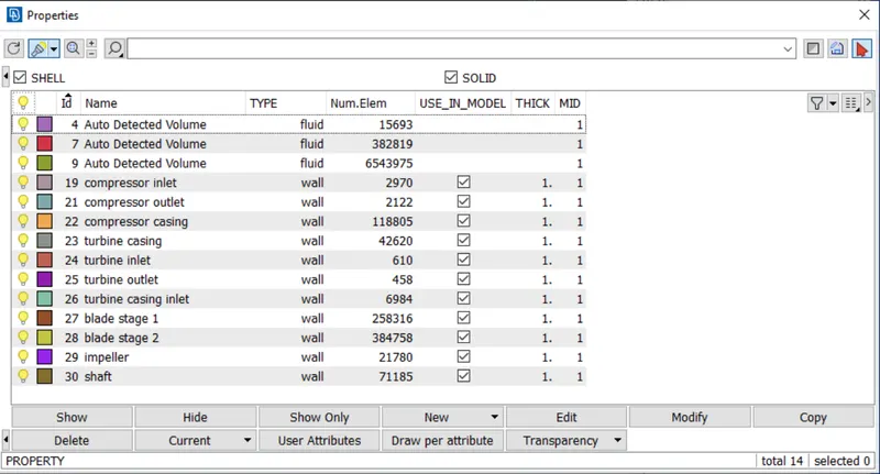
Renaming pid’s
Pid’s should be named according to the object
- Surface meshing:
- We need to mesh each component as per the given criteria in the question, therefore we need to mesh the component individually.
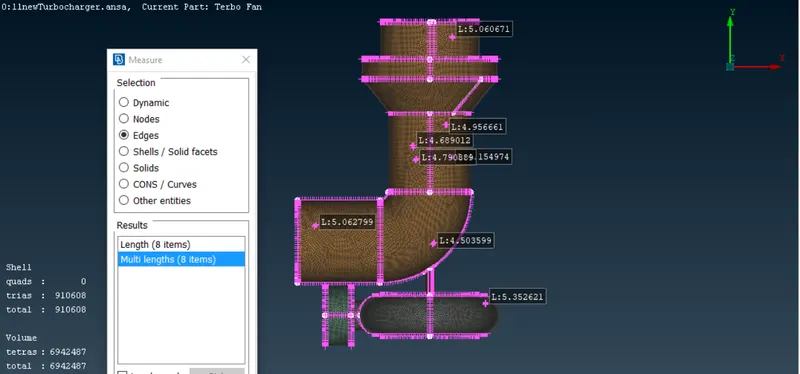
Here we have to give the outer casing 5mm of length so we have freezed the inner object and meshed.
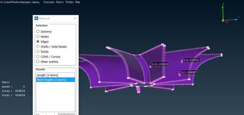
Here impeller length is 2mm
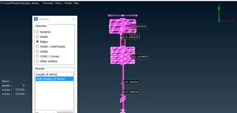
Inner shafts and blades have given 1mm
- Enter the quality and mesh parameters and length of the mesh accordingly for each component.
- The objective of the challenge is to give different mesh lengths for different objects so after giving the mesh lengths and meshing particular objects click on freeze(macros>>freeze/unfreeze) option to freeze the meshed objects so that when we mesh for other objects it doesn’t get changed.
Volume meshing:
1. After the surface meshing is done, we can now achieve volume meshing.
- Under volume meshing, choose define and select whole db(database)in the pop-up window.
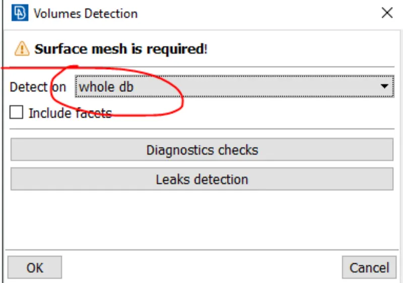
- ANSA identifies various volume present in the geometry, we can delete the unwanted ones and keep the necessary volumes where the fluid can possibly flow in geometry.
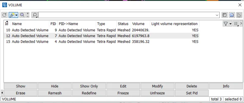
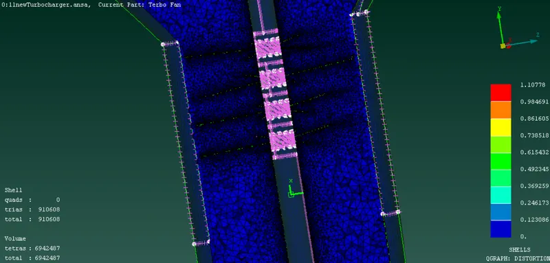
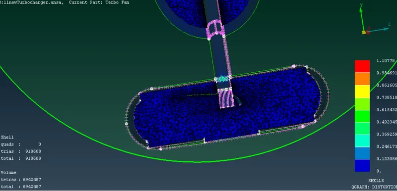
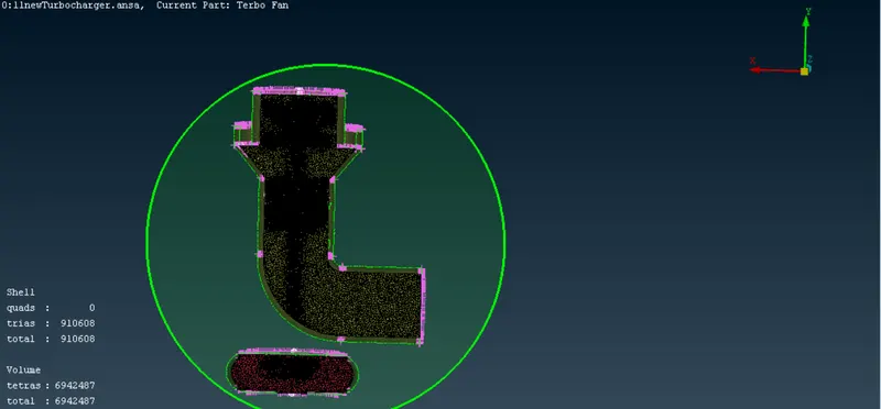
- After the deleting the outer thickness volume and only keeping the fluid volume region, we can remesh each volume using the tetra CFD option under remesh.Using the cut plane we can view the inner view mesh of the model
Learning outcome:
- Checking for geometry errors and correcting the geometry using different geometry editing tools.
- Deleting overlapping regions to improve mesh quality and avoid errors while volume meshing.
- Correcting the triple cons and single cons accordingly as per the geometry requirement.
- Using fine under auxiliaries helps in giving a finer surface finish at the connecting region.
- Creating surface mesh individually and also maintaining mesh length range at the contact region between 2 different mesh lengths.
- Identifying and creating volume mesh only for the fluid region part.
- Tools to create volume mesh.
Conclusions:
- Different mesh length sizes tend to give errors at the contact regions of 2 different mesh length regions, therefore mesh ranges can be given to avoid erasing of mesh.
- Volumetric mesh can be achieved only after creating surface mesh successfully, or else the geometry can give fatal errors while volume meshing.
Hence, we successfully finished volume mesh.
Google drive link https://drive.google.com/file/d/1iCdX8ZL2JBppyQK3yCerIwvHniCG_6hs/view?usp=sharing