Week 3 Challenge
AIM: To Design of Compression Member
INTRODUCTION:
Compression members are commonly used as columns in building structures, chords or webs in trusses, bridge piers or braces in framed structures. The maximum strength of a steel compression member depends, to a large extent, on the member length and end support conditions. Steel compression members are commonly classified as short, intermediate or long members. Each range has its own characteristic type of behaviour. For example, local buckling and/or yielding is the major concern for short compression members while overall buckling affects the strength of long members. Intermediate members are more complex to analyze but also are the most common in steel structures. They may fail by a combination of yielding, overall buckling and/or local buckling including interaction between buckling modes.
Slenderness Ratio
The slenderness ratio is obtained from the following equation:
where:
-
L=the slenderness ratio,
-
k=the buckling length factor.
For compression members, k depends on the rotational restraint at the member ends and the means available to resist lateral movements. For tension members, k=1
-
L=The unsupported length for tension or compression members.
-
r=The radius of gyration corresponding to the member’s effective buckling length (kL).
The buckling factor K .The values in the table depend on ideal cases for pure fixation and hinges in the support. Practically, a hinge support will allow some restraint, and the fixed support will allow some rotation.
| (a) | (b) | (c) | (d) | (e) | (f) | |
|---|---|---|---|---|---|---|
| Theoretical K value | 0.5 | 0.7 | 1.0 | 1.0 | 2.0 | 2.0 |
| Recommended design value when ideal condition are approximated | 0.65 | 0.8 | 1.2 | 1.0 | 2.1 | 2.0 |
| Case end conditions | Rotation fixed and translation fixed | |||||
| Rotation free and translation fixed | ||||||
| Rotation fixed and translation free | ||||||
| Rotation free and translation free | ||||||
PROCEDURE:
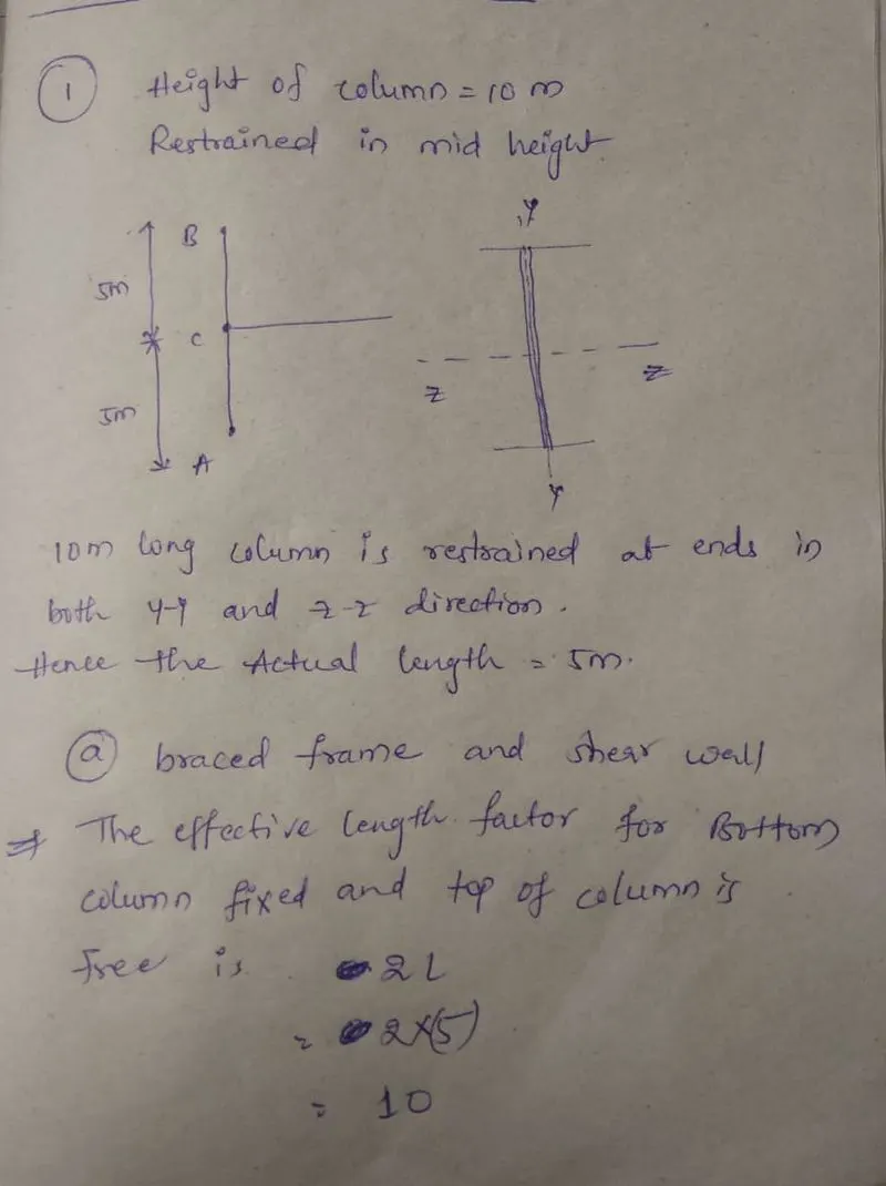
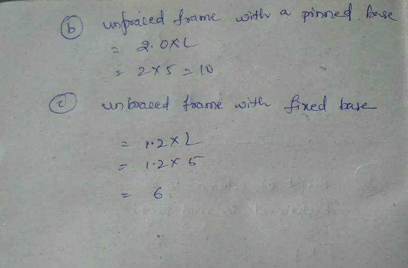
1. Effective length factor determination problem
- Height of column is 10 m and it is effectively restrained in mid height in one direction (in Z direction) but free to move in other direction (Y direction). Bottom of column is Fixed and top of column is Free.
- Calculate effective length factor of columns in following cases
2. Design Axial strength determination of a column with its end conditions
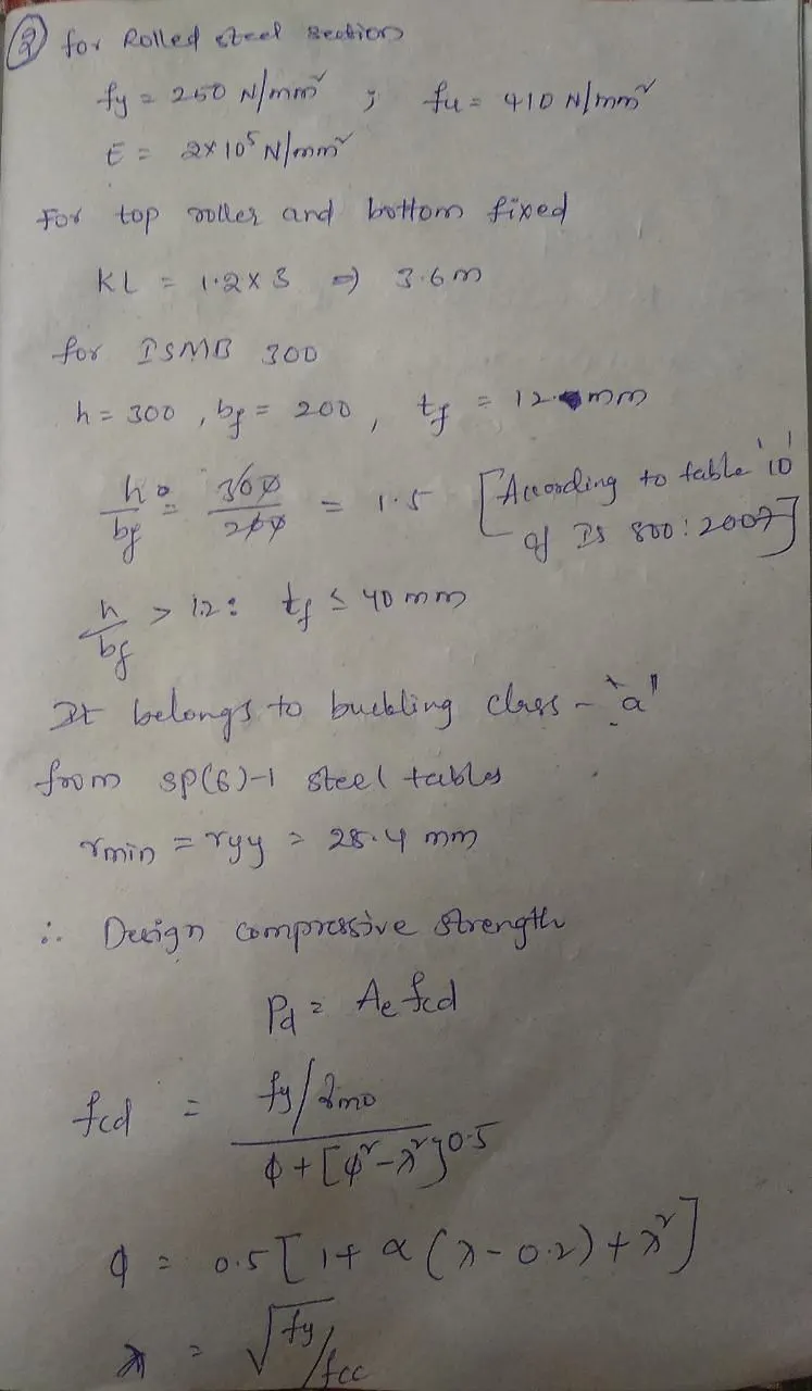
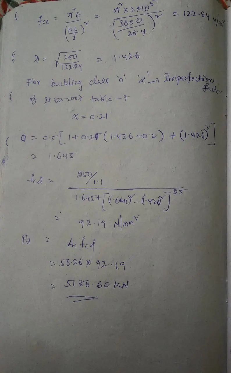
Calculate the Axial compressive capacity of Column made up of Hot rolled ISMB 300 with flange cover plate of 200x12 mm on each flange having length of beam as 3 m. Assume the bottom of the column is Fixed and Top as Roller (Rotation Fixed, translation free). Yield strength of material fy= 250 N/mm2
4. Design of laced column
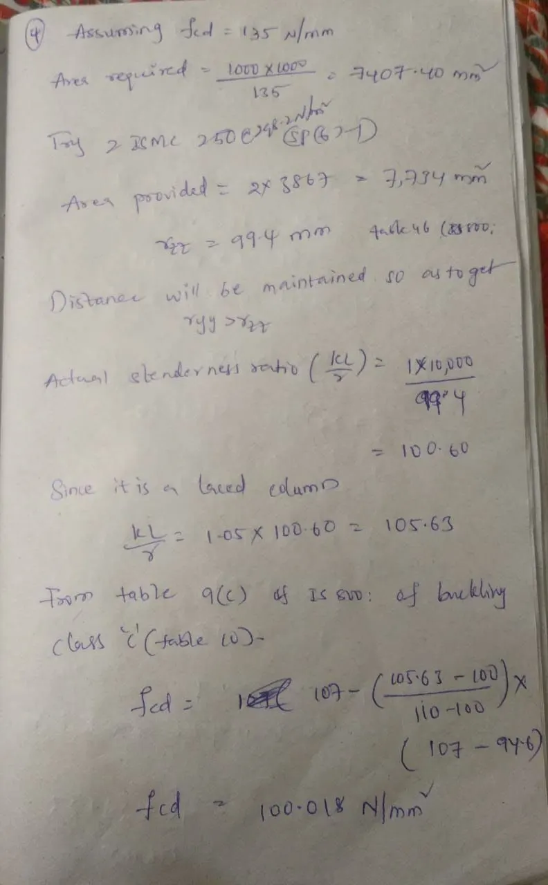
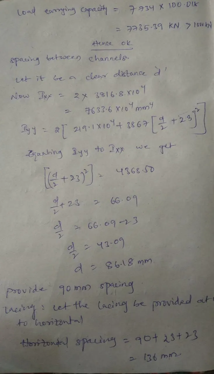
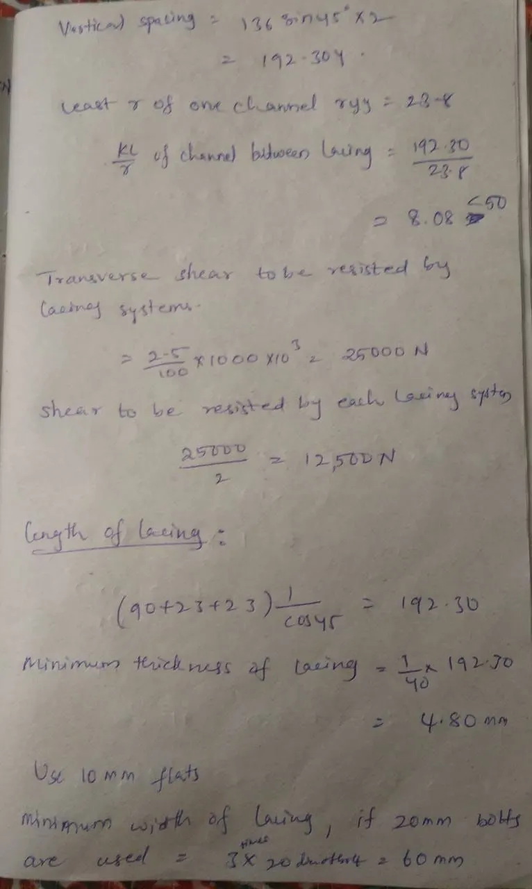
Design a single laced column made up of two channels back to back of 10 m height to carry factored axial load of 1000kN. The lacings are bolted. Design of bolted connection not required.
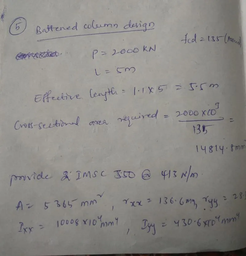
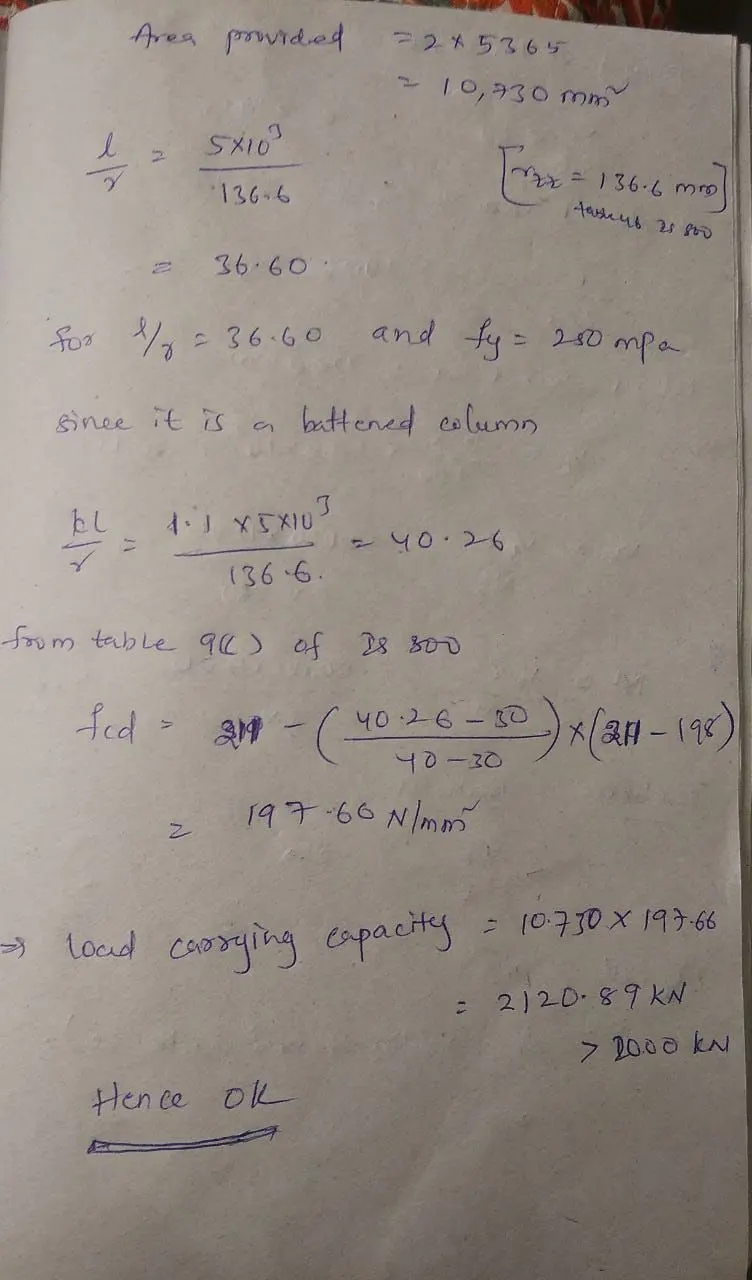
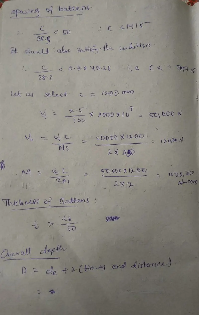
5. Design of battened column
Design a battened column made up of two channels back to back of 5 m height to carry factored axial load of 2000kN. The Battens are welded. Design of weld not required. Use Hot rolled channel sections.