Week 3 Challenge
Q.1
Answer:-
Given data:-
Height of column = 10m
Column is effectively restrained in mid height in one direction (in Z direction) but free to move in other direction (Y direction).
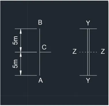
Therefore the actual length (L) is 5m.
a. Braced frame and shear wall:
As per IS 800 : 2007, Table 11.
The effective length factor for Bottom of column is fixed and Top of column is free = 2.0L
Le = 2.0 x 5m = 10m
b. Unbraced frame with a pinned base:
As per IS 800 : 2007, Table 11.
The effective length factor for Bottom of column is pinned and Top of column is free = 2.0L
Le = 2.0 x 5m = 10m
c. Unbraced frame with a fixed base:
As per IS 800 : 2007, Table 11.
The effective length factor for Bottom of column is fixed and Top of column is free = 1.2L
Le = 1.2 x 5m = 6m
Q.2
Given data:-
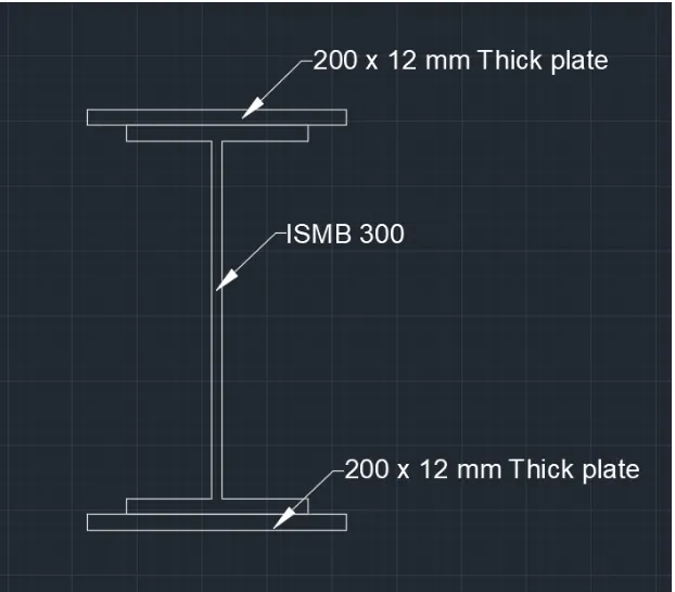
- Section - Hot rolled ISMB 300 with flange cover plate of 200 x 12 mm on each flange.
- Unsupported Length of column is 3 m.
- Bottom of Column is fixed and Top as Roller (Rotation fixed, translation free)
- Fy is 250 N/mm2
Answer:-
Step 1:-
Properties of built-up section:
The built-up column consist of one ISMB 300 and Two cover plates of 200 x 12 mm as shown above.
From steel section tables (SP 6 - Part 1),
Cross section area of ISMB 300 = 5626 mm2
Ixx of ISMB 300 = 8603.6 x 104 mm4
Iyy of ISMB 300 = 453.9 x 104 mm4
Cross section area of Plate = 2400 mm2
Moment of inertia of built-up section about xx-axis
Ixx = [8603.6 x 104 + 2 x 200 x 123 x (1/12) + 2 x Ah2]
= [8603.6 x 104 + 5.76 x 10⁴ + 2 x 2400 x (150+12/2)]
= [8603.6 x 104 + 5.76 x 10⁴ + 74.88 x 10⁴]
Ixx = 8684.24 x 104 mm4
Moment of inertia of built-up section about yy-axis
Iyy = [453.9 x 10⁴ + 2 x 12 x 2003 x (1/12)]
= [453.9 x 10⁴ + 1600 x 104 ]
Iyy = 2053.9 x 104 mm4
Step 2:-
Slenderness ratio:
Iyy is less than Ixx. Therefore ryy is Minimum.
Minimum radius of gyration rmin = (Iyy / A)1/2
= (2053.9 x 104 / 10426)1/2
rmin = 44.38 mm
Unsupported Length (L) = 3 m = 3000 mm.
Effective Length (Le) = 1.2 x L = 3600mm
Slenderness ratio of the column = (L/rmin ) = 3600/44.38 = 81.12
Step 3:-
Safe Load:
From IS 800 : 2007
For L/r = 81.12 and the steel having yeild stress, Fy is 250 N/mm2
Allowable working stress in compression
fcd = 138 N/mm2
Safe load carrying capacity of builtu-up section P = fcd x A = 138 x 10426 = 1438788 N
P = 1438.788 kN
Result:-
Design Strength = 1438.788 kN
Q.3
Given data:-
Length of strut member = 2 m
Factored axial load = 400 kN
Fy = 210 N/mm2
Assume the ends of member are simply supported
Hence Le = 1.0 x L = 2 m = 2000 mm.
Answer:-
Required area of cross section = P / Fy
= 400 x 103 / 210
=1904.76 mm2
From IS 4923 : 1997, Table 1
For a circular hollow section of 125 outer bore dia = 139.7 thickness = 4.5, Area of circular section = 1910 mm2
For a square hollow section of 100x100x6 has a Area of square section = 2163 mm2
From IS 800 : 2007, Table 2
Limiting Width to Thickness ratio of circular section should be lesser than 88 e2
e = (250/Fy)1/2 = 1.09
D/t = 139.7 / 4.5 = 31.04
88 e2 = 95.92
Width to Thickness ratio of circular section is lesser than 88 e2
Hence safe.
From IS 800 : 2007, Table 10
Square tube Sections comes under class a
For circular section Slenderness ratio λ=L/rmin = 2000/47.8 = 41.84 < 180
For square section Slenderness ratio λ= L/rmin =2000/37.9
L/rmin = 52.77 < 180
Hence safe.
From table 9a of the code for fy = 210
For circular section fcd = 180 N/mm2
For square section fcd = 174.1 N/mm2
Hence, the design strength for circular section = 180 x 19.10 = 343.8kN.
Q.4
Given data:-
Height = 10m
Factored axial load = 1000kN
Assume design stress of 125 N/mm2 (0.5 fy)
Required area =1000x103 / 125=8000 mm2
Answer:-
Assume the column to be built up of two ISMC 300 channels placed back-to-back
Cross section area of each channel = 4564 mm2
Cross section area of two columns (A) = 2 x 4564 = 9128 mm2
rxx = 118.1 mm
ryy = 26.1 mm
tf = 13.6 mm
tw = 7.6 mm
cyy = 23.6 mm
Ixx for two channel = 2 x 6362.8 x 104 mm4 = 12725.2 x 104 mm4
Iyy for one channel = 310.8 x 104 mm4
The distance back to back 'S' between the channels is so adjusted as to make rxx = ryy
L/rxx = 10 x 103 / 118.1 = 84.67
L/r of the built-up section should be taken as 1.05 x 84.67 = 88.90
fcd taken from code for given rxx = 120 N/mm2
Permissible axial load = 9128 x 120 = 1095 kN > 1000 kN.
Hence the section is safe.
Spacing of channels = 12725.2 x 104 = 2 (Iyy + A (S/2 +Cyy)2)
=2 x (310.8 x 104 + 4564 (S/2 +23.6)2)
solving the above equation S = 183.1mm
Design of Lacing:
Using the single lacing bar inclined at 45 degree with the column axis.
Lacing system of the built-up section using single lacing system with the inclination of lacing bar gauge length g = 50 mm for 90 mm flange
Spacing of lacing bars Lo= 2 x (183 + 50 x 2) cot 45
= 2 x 283 x 1 = 566 mm
For a single column element, slenderness ratio Lo / ryy should be < 0.7 x L/r of whole column
566 / 26 = 21.76 < 0.7 x 88.98=62.3
Hence safe.
Transverse shear force (V) = (2.5 /100) x axial load = (2.5/100) x 1000 x 103 = 25 kN = 25000 N
Transverse shear in each panel = V/N = 25000/2 = 12500 N
Compressive force in the lacing bar =(V/N) cosec45
= 12500 x1.414
=17675 N
Q.5
Given data:-
Height = 5m
Axial load= 2000 kN
Answer:-
Assume design stress of 150 N/mm2 (0.6 fy)
Required area =2000 x 103 / 150 = 13333 mm2
Assume the column to be built up of two ISMC 350 channels placed back-to-back
Cross section area of each channel = 5366 mm2
Cross section area of two columns (A) = 2 x 5366 = 10732 mm2
rxx = 136.6 mm
ryy = 28.3 mm
tf = 13.5 mm
tw = 8.1 mm
cyy = 24.4 mm
Ixx for two channel = 2 x 10008 x 104 mm4 = 20016 x 104 mm4
Iyy for one channel = 430.6 x 104 mm4
The distance back to back 'S' between the channels is so adjusted as to make rxx = ryy
L/rxx = 5 x 10³ / 136.6 = 36.60
fcd taken from IS 800 : 2007 Table 9c for given rxx = 202.4 N/mm2
Permissible axial load = 10732 x 202.4 = 2172 kN > 2000 kN.
Hence the section is safe.
Spacing of channels = 20016 x 104 = 2 (Iyy + A (S/2 +Cyy)2)
=2 x (430.6 x 104 + 5366 (S/2 +24.4)2)
solving the above equation S = 333.4 mm
Spacing of battens Lo/ryy should be less than 50 or 0.7x L/ryy
Lo/ryy < 0.7 x 36.6
Lo < 0.7 x 36.6 x 28.3 = 725 mm
Also, Lo/ryy should be less than 50
Lo/ryy < 50
Lo < 50 x ryy = 50 x 28.3 = 1415 mm
Hence provide batten at spacing 725 mm
Size of end battens
Overall depth of batten = 334 + 2 x Cyy
= 334 + 2 x 24.4= 383 mm
Provide 60 mm overlap of batten on channel flange for welding
Length of batten = 334 x 2 x 60 = 454 mm = 460 mm
Thickness of battens = 1/50 x 460 = 9.2 mm
Provide batten size = 460 x 390 x 9.2 mm
Size of intermediate battens
Overall depth = 3/4 x 390 = 293 mm
Provide 460 x300x 9.2 mm.