Week 3 Challenge
Question 1
1. Primary load cases are used as follows
- Dead
- Live
- Temperature
- Roof live
- Wind
- Seismic
- Accidental
- Flood
- Soil
- Dust
- Crane Hook
- Gravity
2. The one-way slab is a slab, which is supported by parallel walls or beams, and whose length-to-breadth ratio is equal to or greater than two and it bends in only one direction (spanning direction) while it is transferring the loads to the two supporting walls or beams, because of its geometry.
3. Structural Steel = 7850 kg/m3
Soil = 16- 24 kg/m3
4. few sections that can be defined using the Properties tab in STAAD Pro
- Circle
- Rectangle
- Trapezoidal
- General
- Tapered
- Assigned Profile
- Tapered Tube
- Tapered I
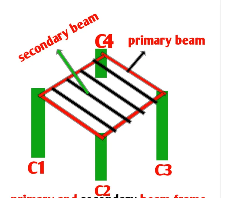
5. Primary Beams - the beams that are connecting columns for transferring loads of a structure directly to the columns are known as primary beams.
Question 2.
1. factors and parameters that influence the design pressure intensity of a high-rise building.
- Loading
- Sequential Loading
- Strength and Stability
- Stiffness
- Drift Limitations
- Human Comfort
- Creep, Shrinkage, and Temperature
- Fire
2. The load transfer process of a Reinforced Concrete Building
- floor loads are usually transferred from slabs to beams, and from the beams, the loads are transferred to the columns and from columns, it is transferred to the foundations.
Question 3.
1.
- comparison between one-way and two-way slab
-
The one–way slab is supported by a beam on two opposite sides only. the two–way slab is supported by the beam on all four sides. In one–a way slab, the load is carried in one direction perpendicular to the supporting beam. carried in both sides ending bending moment occurs in a singular direction bending Bending moment in both directions One-way slabs have less steel moreteel More content of steel type of deflection is a cylinder type of deflection is slightly curved The one-way slab can be defined as the type of slab in which the ratio of the longer span to the shorter span is greater than two ratio ratio of longer span to shorter span is equal or less than two loading in one direction Trapezoidal and triangular loading.
2. Concept of Secondary Beam
- The beams that are connecting primary beams for transferring loads of a structure to the primary beams are known as secondary beams. These beams are provided for supporting and reducing the deflection of beams and slabs.
- those types of horizontal flexural (beam) structure members which directly connected to the primary beam and not connected directly to the column. This beam is known as a secondary beam which Safely transfers the load to the primary beam acting on it by the slab.
3. Primary load cases
- A) Dead Load - IS 875 PART1
Imposed Load - IS 875 PART 2
Wind Load -IS 875 PART 3
Seismic load - IS 1893-2016
IS 875-4 (1987): Code of Practice For Design Loads
- B) & C)
- Dead Load-
- The dead load is defined as the continuous load in a structure i.e the load of machine etc and this load caused by the weight of the members that are permanently attached to the particular structure.
- The dead load of the structure comprised of the load of the column, load of the beam , loads of the floor slab, roofing, walls, the load of the windows or may be the load of the electrical fixture. All the loads which is permanent on the structure is called as the dead load of the structure.
-
Some of the Dead Load(Unit Weight) of the following materials:
- Cement : 1440 Kg/cu.m.
- Steel : 7850 Kg/cu.m.
- Sand : 1600 Kg/cu.m.
- Concrete : 2400 Kg/cu.m.
- RCC : 2500 Kg/cu.m.
- Soil : 1800 Kg/cu.m.
- Dead Load factor is 1.
- Live load ----
-
- Live loads are the loads that are fully or partially vary from time to time on the structure.
- Live loads are not constant loads throughout of the life span of a structure.
- Live loads may vary time to time according to its usage or the occupancy.
- Live load may vary depend on the type of the structure such as the residential building, commercial building, industrial building etc.
- For residential building we use 3KN/sq.m Live Load.
- Live loads on floors and the roofs consist of all loads which are temporarily placed on the structure.
Some of the live loads (Unit Weight) are:
- All rooms and kitchen : 2 KN/sq.m.
- Bathrooms and Toilets : 2 KN/sq.m.
- Balcony : 3 KN/cu.m.
- Staircase/Corridors : 3 KN/cu.m.
- Earthquake Loads- Seismic loading is one of the basic concepts of earthquake engineering which means application of an earthquake-generated agitation to a structure. It happens at contact surfaces of a structure either with the ground, or with adjacent structures, or with gravity waves from tsunami.
4. steps involved in assigning Properties and Support to a model using STAAD Pro sequentially.
- Firstly we draw the geometry of the structure
- Then we cllick on the button for the properties
- then this window apears
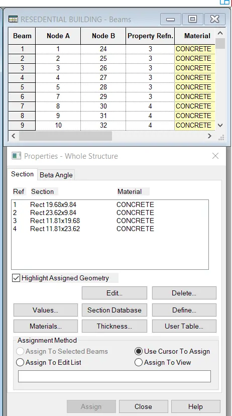
- Click on define
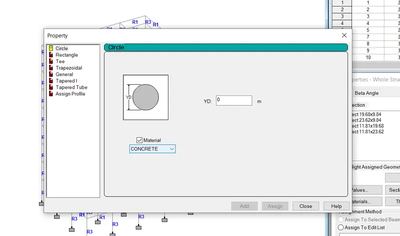
- THen assign the proper as shown
- Now we shift to the support tab
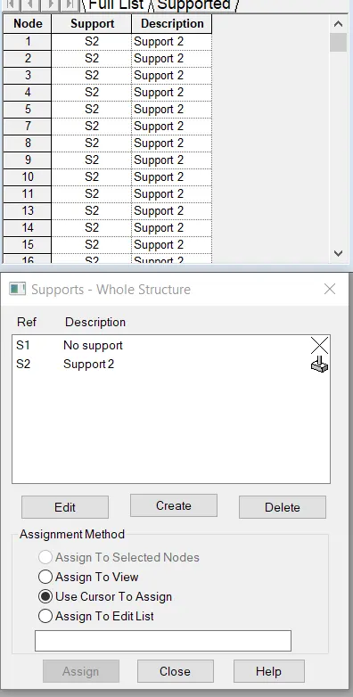
- Click on Create and attach to the nodes at the foundation of the structure.
5.
Brief the steps to be followed to create and assign secondary beams in STAAD Pro
- The steps that are involved in creating and assigning the secondary beams in STAAD Pro are discussed below:
- In order to assign the secondary beam in the model, first we need to right-click on the screen and select the cursor as the beam cursor.
- After that click the primary beam and right-click on the beam ,after that there will be a list of various options appears on the screen and in that list there will be an option called add node at the mid-point just click on that option.
- After clicking on that option the node at the mid-point of the primary beam added automatically.
- After added the node at the mid-point of the primary beam, now we have to draw the beam, and to add beam we need to go to the option Add beam and start adding the beam from the created node and create beam from the node that we have just created up to the opposite primary beam.
- And the thing is that the software automatically locates the mid-point at the another beam, and that is how the beam has been added on the nodes. And this beam is called as the secondary beam.
- And now after creating the secondary beam we need to make the secondary beam the simply supported beam.
- And in order to do that first select the beam after that go to the specification tab then there will be an option called beams just click on that option.
- And after this there will be another option called releases just select Fx and then Mz.
- After this there will be an option called Add just click on that option and then click on the OK.
- And now we have to assign support to the model or structure, and to assign the support select the support that we have just created from the created section, and click on the opinion Assign to the selected view and then click on the assign option and then assign the property and done.
Practical
- o calculate the wind pressure for the given building.
PROCEDURE:
Given Data :
Building dimensions : 20m X 30m X 20m.
Building usage : Hospital Block.
Location : Darjeeling.
STEP 1: Calculate Design Wind Speed:
We know the formula to calculate the design wind speed, that is:
Vz=Vbxk1xk2xk3xk4
where, Vb = Basic Wind Speed (m/sec).
k1 = Risk Co-efficient.
We can find the value of risk co-efficient,k1 from IS code 875:Part 3 2015, Table 1).
k2 = Terrain Roughness and Height Factor.
k3 = Topography Factor.
We can find the value of topography factor from IS cide 875:Part 3 2015 clause no 6.3.3.
k4 = Importance factor.
Given Data form the IS code:
- Vb = 47 m/s.
- k1 = 1.07.
- k2 = 0.8.
- k3 = 1.
- k4 = 1.
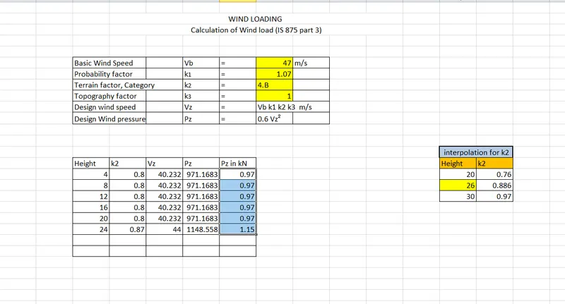
Similarly, we can calculate the for different heights, the calculation for different height has been done in the excel sheet so the excel sheet has been given below:
Live Load:
- We can calculate the live load of a given structure by using the IS 875:Part 2,which states different live loads values for different rooms.
- As our building is the Hospital building, the all the proposed live load values for hospital building according to the IS 875:Part 3 has been listed below: