Week 3 Challenge
Aim :
1.To note how hydrology and geotechnical studies (preliminary and detail studies, zone of influence) are used in fixing span as per IRC standards and type of bridge and mention the clauses applicable for the same.
2. To determine the scour depth at the pier and abutment location
3. To mention measures to be taken to avoid scour at bridge for shallow foundation and draw the section of measures on the downstream and the upstream
4. To explain what is uplift and how it can affect the foundation. (loss of contact)
5. To calculate the uplift in U trough of given section with height 3,4,5 meters. with water level on top of ramp wall level .
6. To mention different measures that can be taken to avoid uplift.
Introduction: The given data has Silt factor =3, Design discharge = 1000 cumecs and Linear waterway = 128m. A U trough is given with carriage way width of 8.2m and footpath 1.2m
Procedure:
Details are put up as per IRC 5 AND IRC 78 Code.
Q1.How hydrology and geotechnical studies (preliminary and detail studies, zone of influence) are used in fixing span as per IRC standards and type of bridge and mention the clauses applicable for the same.
A1.
Hydrology study gives us all the data regarding water flow on the site like design discharge that helps in deciding total length of the bridge as per IRC 5 Cl.106.3 and Cl.106.4, It provides High flood level with which height of bridge and type of bridge is decided. It provides scour level details with which foundation level is decided. It provides water velocity with which type of substructure is decided.As per Cl.104.1.3.The preliminary site selection can be based on information contained in the topographical sheets of the Survey of India, supplemented by actual survey or study of satellite images of the location, which can be obtained from the National Remote Sensing Agency. A model study may be required for bridging rivers having undefined cross section and huge flood plains. As per IRC 78 Cl.703 HFL and scour details studies shall be conducted.
The geotechnical report is the tool used to communicate the site conditions and design and construction recommendations to the roadway design, bridge design, and construction personnel. As per IRC 78 Cl.704,
During Preliminary Investigation Stage
As a part of site selection process to study existing geological maps and other information, previously prepared and available site investigation reports, known data of nearby structures, if any, surface examination about river bed and banks, etc., which will help in narrowing down of sites under consideration IRC:78-2014 for further studies for project preparation stage.
Detailed Investigation Stage
To determine the characteristics of the existing geo-materials, like, soil, rock, bed material in water courses, etc. in the zone of influence of the proposed bridge sites in such a way as to establish the design parameters which influence the choice and design details of the various structural elements, especially the foundation type.
During Construction Stage
To confirm the characteristics of geo-materials established in stage (ii) based on which the design choices are made and to re-confirm the same or modify to suit the conditions met at specific foundation locations.
Zone of Influence
Zone of influence mentioned above is defined as the full length of the bridge including portion of wing/return wall and part of approaches covering,(but not restricted to), the full flood zone for water courses, and upto depth below proposed foundation levels where influence of stresses due to foundation is likely to affect the behaviour of the structure, including settlement, subsidence under ground flow of water, etc. The width of the land strip on either side of the proposed structure should include zones in which the hydraulic characteristics of river water are likely to be changed affecting flow patterns, scour,
IRC 5 Cl.101.6 Bridge
A bridge is a structure having a total length of above 6 m for carrying traffic or other moving loads across a channel, depression, road or railway track or any other obstruction.
IRC 5 Cl.101.13 Culvert
Culvert is a structure having a total length of upto 6 m between outer faces of walls, measured at right angles. Cross drainage structures with pipes will be termed as culvert, irrespective of length.
IRC 5 Cl.101.17 Foot Over Bridge (FOB)
A foot over bridge is a bridge over a road or other obstructions, for exclusive use of pedestrians.
IRC 5 Cl.101.39 Road Over Bridge (ROB)
Road Over Bridge is a bridge built over the Railway tracks.
IRC 5 Cl.101.40 Road Under Bridge (RUB)
Road under bridge is a structure built beneath the Railway tracks.
Q2.Determine the scour depth at the pier and abutment location having silt factor =3 Design discharge = 1000 cumecs Linear waterway = 128 m
A2. Given Data : silt factor =3, Design discharge = 1000 cumecs, Linear waterway = 128 m.
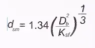
As per IRC 78 The mean scour depth below Highest Flood Level (HFL) for natural channels flowing over scourable bed can be calculated theoretically from the following equation:
Where
Db = The design discharge for foundation per metre width of effective waterway.
Ksf = Silt factor for a representative sample of bed material obtained upto the level of anticipated deepest scour.
As per IRC SP 13 The value of Db shall be total design discharge divided by the effective linear waterway between abutments or guide bunds.
Regime surface width of the stream
W=4.8Q^(1/2) =4.8*(1000)^1/2 = 151.7m < Linear water way (128m)
Db = 1000/128 = 7.81m3/s per m width
Ksf = 3
dsm=3.66 m
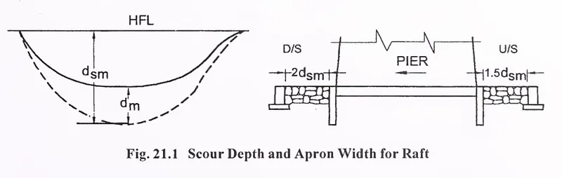
Max Scour depth for pier = 2xdsm = 7.32m.
Max Scour depth for abutment with approach retained or lowest
bed level whichever is deeper = 1.27xdsm = 4.65m
Max Scour depth for abutment with scour all around = 2xdsm = 7.32m.
Q3.What measures can be taken to avoid scour at bridge for shallow foundation. Also draw the section of measures on the downstream and the upstream side.
A3.
As per IRC SP 13 Article 20 To avoid scouring following measures can be followed,
- Provide protection works -The rigid flooring should be provided under the bridge and it should extend for a distance of at least 3 m on upstream side and 5 m on down stream side of the bridge. However, in case the splayed wing walls of the structure are likely to be longer, the flooring should extend upto the line connecting the end of wing walls on either side of the bridge. The top of flooring should be kept 300 mm below the lowest bed level. Flooring should consist of 1 50 mm thick flat stone/bricks on edge in cement mortar 1 :3 laid over 300 mm thick cement concrete Ml 5 grade laid over a layer of 1 50 mm thick cement concrete M10 grade. Joints at suitable spacings (say 20 m) may be provided.
- Providing flexible and rigid aprons - Flexible apron 1 m thick comprising of loose stone bouiders (weighing not less than 40 kg) should be provided beyond the curtain walls for a minimum distance of 3 m on upstream side and 6 m on downstream side. Where required size stones are not economically available, cement concrete blocks or stones in wire crates may be used in place of isolated stones. In this context, relevant provision in IRC:89-1997 is also referred.20. 1 .2.5. Wherever scour is restricted by provision of flooring/flexible apron, the work offlooring/apron etc., should be simultaneously completed alongwith the work on foundations so that the foundation work completed is not endangered.
- Provide Cut off walls / curtain walls - The rigid flooring should be enclosed by curtain walls (tied to the wing walls) with a minimum depth below floor level of 2 m on upstream side and 2.5 m on downstream side. The curtain wall should be in cement concrete Ml 5 grade or brick/stone masonry in cement mortar 1:3. The rigid flooring should be continued over the top width of curtain walls. In this context,
relevant provision in "Guidelines for design and construction ofriver training and control works for road bridges", IRC: 89-1997 is also referred. - Providing adequate depth of foundation

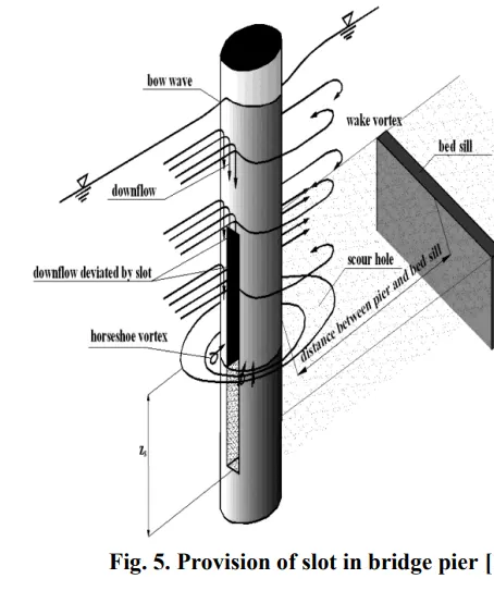
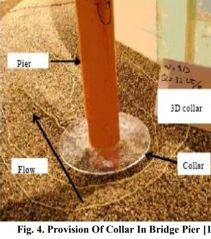
Reduction of scouring is possible by different approaches, using different countermeasures. Ripraps and geo bags reduce the scouring up to 40-50%. Collars reduces the scouring at great extent if it is placed at or below river bedlevel. Rectangular collar reduces the scouring to 79% Collar having dimension 1.5 to 2 times the pier dimension reduces the scouring in the range 55% to 96% Slot is most efficient if the angle between slot and the current is in the range 20°. If the slotwidth is one fourth of the pier diameter the scour reduction is 20% and if the width is one half of the pier diameter, the scour reduction is 30%.If the slot is placed at river bedlevel,it reduces the scouring to 60-88%. Scouring reduction of 100% is possible by using both collar and slot incombination.
Q4.What is uplift and how it can affect the foundation. (loss of contact)
A4.
An uplift pressure is any upward pressure applied to a structure that has the potential to raise it relative to its surroundings. Uplift forces can be a consequence of pressure from the ground below, surface water and so on. When there is an impermeable layer between the bottom of the excavation and a deep aquifer, the ground water head at the acquifer below the subgrade might be sufficiently high to cause soil layers to lose strength.Water pressure can exert an uplift force on a structure due to high rainfall, for example by causing clay soils to expand. This can be problematic if the upward forces are greater than the forces being exerted downwards by the structure. To overcome this risk, the structure must be designed to provide greater resistance against uplift forces, and also a drainage system to relieve the water pressure.
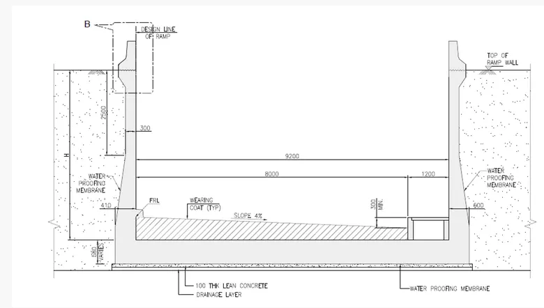
Q5. Calculate the uplift in U trough of below section with height 3,4,5 meters. with water level on top of ramp wall level
A5.
For H=3m
| Width of base slab | = | 10.21 | (9.2+0.41+0.6) |
| Area per m width (A) | = | 10.21 | m2 |
| Ỵw | = | 10 | kN/m3 |
| H | = | 3 | m |
| depth of base slab | = | 0.68 | m |
| h | = | H+depth of base slab | |
| 3.68 | m | ||
| Uplift pressure | = | Ỵw*h | |
| = | 36.8 | kN/m2 | |
| Uplift force per m | = | Ỵw*h*A | |
| = | 375.728 | kN/m | |
For H=4m
| Width of base slab | = | 10.21 | (9.2+0.41+0.6) |
| Area per m width (A) | = | 10.21 | m2 |
| Ỵw | = | 10 | kN/m3 |
| H | = | 4 | m |
| depth of base slab | = | 0.68 | m |
| h | = | H+depth of base slab | |
| 4.68 | m | ||
| Uplift pressure | = | Ỵw*h | |
| = | 46.8 | kN/m2 | |
| Uplift force per m | = | Ỵw*h*A | |
| = | 477.828 | kN/m | |
For H=5m
| Width of base slab | = | 10.21 | (9.2+0.41+0.6) |
| Area per m width (A) | = | 10.21 | m2 |
| Ỵw | = | 10 | kN/m3 |
| H | = | 5 | m |
| depth of base slab | = | 0.68 | m |
| h | = | H+depth of base slab | |
| 5.68 | m | ||
| Uplift pressure | = | Ỵw*h | |
| = | 56.8 | kN/m2 | |
| Uplift force per m | = | Ỵw*h*A | |
| = | 579.928 | kN/m | |
- Toeing in the Foundation into the Surrounding Ground
When a substructure is built inside an open excavation or temporary cofferdam, the base slab or raft foundation can be extended outside perimeter to increase resistance to uplift.
The weight of backfill material on the tied-in foundation increase the weight of the structure against uplift pressure. This method is not feasible where a diaphragm or secant pile wall is used as a permanent retaining structure.
- Increase Self-weight of the Structure
The self-weight of the building can be increased by increasing the size of structural members. sometime, the dead weight of the low-rise podium in a high-rise complex is increased by incorporating a rooftop garden with a thick soil fill.
- Ground Anchors
Pre-stressed anchors can be used as a temporary measure to counteract uplift forces. Permanent application of ground anchors is limited by concerns about their long-term performance with respect to corrosion.
- Piling Method
The piling method is the most effective method to resist Uplift pressure. Various types of piles are available to be used for countering uplift pressure based on soil condition and their necessity on site.
For instance, end bearing pile, friction pile, un-reamed pile, sheet pile, tension pile, and compaction pile. Table 1 presents different types of piles used to contain uplift pressure based on soil conditions.
Table 1 Types of Piles Chosen Based on Soil Conditions to Withstand Uplift Pressure
|
Types of Pile |
Suitable Types of Soil |
|
End bearing pile |
Used when bedrock or rocklike material is present at a site within a reasonable depth. Piles are extended to the rock surface. The ultimate bearing capacity of the pile based on the underlying material. |
|
Friction pile |
It is used in cohesionless soil in which end bearing pile would be very long and uneconomical. The load on pile is resisted mainly by skin/friction resistance along the side of the pile. Capacity of the pile is a function of the shaft area in contact with the soil. Friction piles are often used to increase the density and thus the shear strength of soil. |
|
Unreamed pile |
It is used in black cotton soils, filled up ground and other types of soils having poor bearing capacity. |
|
Sheet pile |
Sheet piles, which made of thin plates of concrete; timber; or steel, driven into the ground for separating members or stopping seepage of water. it is not constructed for carrying any vertical load. |
|
Tension pile |
Tension piles uplift piles anchor down the structures subjected to uplift pressure. |
|
Compaction pile |
It is driven in loose granular soil |
- Redistribution of base pressure is generally done.
3 cases of distribution - e<B/6, e=B/6 & e>B/6 where e= eccentricity and B= width of footing as shown below
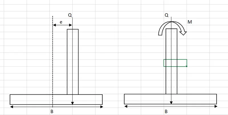
Anchors are provided at the base of footing designed for uplift force or tension generated.