Week 3:- BiW Fixture Design Methodologies Challenges
1. DESIGN METHODOLOGY:- These are the steps that are used for designing a BIW fixture in the automotive industry. The steps involve the following procedure:
- Purchase Order: When the customer has completed all the price background with other vendors and also has checked their background i.e. the quality of production, projects involved, etc. He/She decided to share a purchase order (PO) with the best vendor. This PO mentions the quantity and payment schedule to the vendors.
- Input from Customer: When the PO from the customer is received, the Technical team of the manufacturer discusses with the customer about the input files like 3D/2D geometric specifications, functional requirement, Standards that are to be used, Layout, Weldstudy plan, Standard Templates for detailing, etc.
- Percentage of Completion Criteria: The Design team studies all input files and prepare a design study plan for the customer that defines the percentage criteria involving the percentage completion for all stages starting from input and concept design to the final dispatch and inspection by the client.
- Design Output: Design Output is not only the study of CAD/CAM done by the design team. It includes many documents that should match the inputs that were provided by the customer. This output mentions full details of layout, weld study, part list, ergo data, standard units used in the fixture, etc.
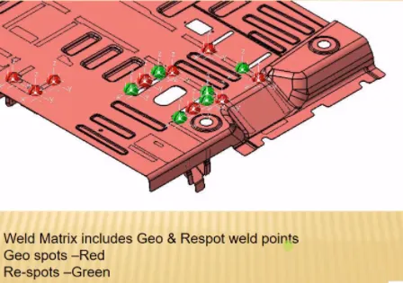
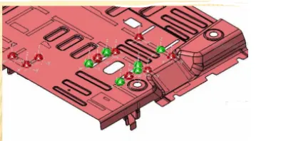 - Red(respot-tool), green(geo-tool)
 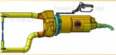 (weld-gun details)
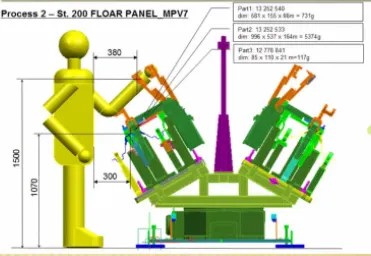 (ergo data)
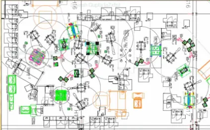 (Layout that defines the movement of the robot, tool changing, rotations, etc)
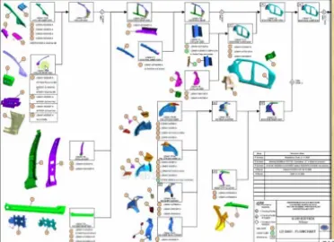 (Part assembly line)
2. Inputs required from a customer to design a fixture are as follows:
- Functional requirement: This input from the customer defines what type of fixture do they need i.e the function that a fixture should perform in BIW to completely assembly the car body panel. These requirements include welding fixture, hemming fixture, clamping fixture, etc.
- Standard Preferred: This input defines the standards while designing a fixture that uses standard units or components from companies like NAAMS, ABB, ZYTRAN, DESTACO, TUNKERS, etc. that manufacture components like swivel cylinders, risers, clamp units, slider units, sensors, etc.
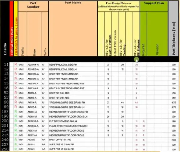
- Standard Parts: This input states the list of parts that are to be used in fixtures with product name, code, quantity, and material. It also states the number of holes, welds that are to be used in the fixture.
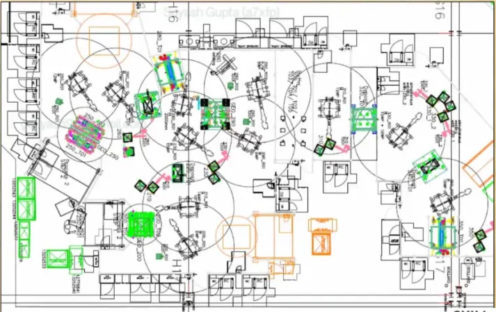
- Layout: The layout of the placement of all grippers, stands, BIW stations, fixtures is provided by customer input which defines the movement and placement of BIW stations/fixtures throughout the assembly line. It also shows the map of full tooling, replacement of tools in BIW robots.
- Product Assembly: The input file for the Product assembly line is also given. That helps the manufacturer to properly understand all the components that are to be used in BIW fixtures for locating them. A 3D detailing template for the same is provided.
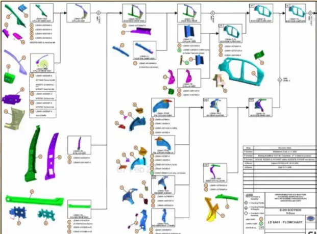
- Standard Detailing Template: Templates for detailing the fabrication parts for BIW are provided so that the manufacturer could use that template while designing the design tree.
3. Input from Car Products:
- The input of car products helps the manufacturer in determining the GD and T of the car panel i.e.which surface is flat, round, cylindrical. It helps in determining the coordinates using CMM.
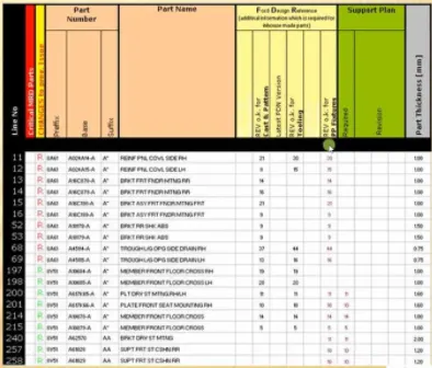
- A list of Parts with the location of each part, thickness, and the part number is provided for each Car panel.
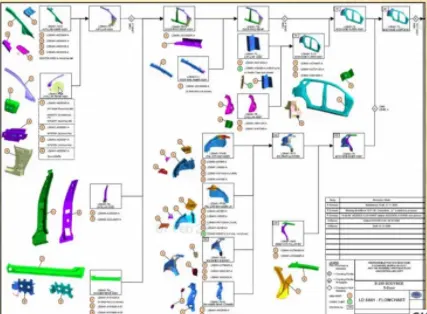
- A full product assembly sheet of the Car panel is provided by the customer.
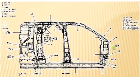
- Apart from the Product plan, part list, and 2D/3D CAD, clamp plan of part fixture is also given as input by the customer.
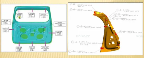
4. CLAMP PLAN: The clamp plan provides the information on locating pins, rest units, shims, mylars, risers, blades, pivots, swivel cylinders, hardware, etc. of the car panel to help the manufacturer in placing the panel fixture.
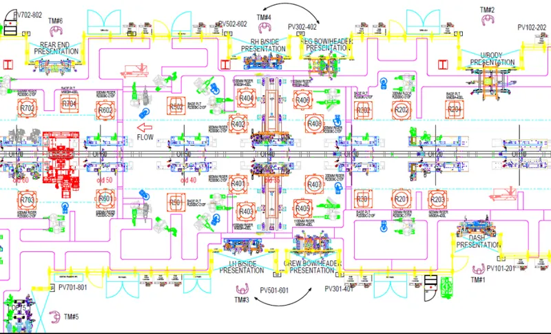
5. The purpose of the Layout is to provide a full assembly line plan of a BIW fixture that shows the position of robots, tool changing/replacement room. It shows the route of each robot or gripper of the flow of the panel part fixture.
The layout of the assembly line briefs the rotational and translational limit of robots to brief the manufacturer about what multiple tasks can that particular robot perform. This saves the time and the cost of building a fixture.
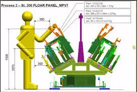
6. Ergo Data: Ergo Data is the ergonomics i.e how a manikin would be operating a fixture. at what maximum distance it could extend its arms and stand at a minimum distance to be on the safe side such that he/she can easily place the fixture.
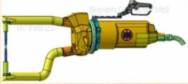
7. Weld Study: It provides the details of the weld gun that is mounted on the gripper, the position of weld spots, and the tools that are to be used. It is a clear study of joining through the welding process.
8. Percentage completion criteria:
- Input and Concept design: Gathering the inputs from customers and applying them to the initial design in the car panel. This completes 0-25% of the Fixture design process.
- Concept approval and Simulation check: After the concept design is developed it is discussed with Design managers and heads and is simulated after approval. If the simulation check fails due to some changes, the changes are adopted and again simulated. It governs 25-40% of the completion criteria.
- Design freezing and Detailing: When approval of the design is done, a 3D model is created using part and product design with proper tree structure, and 2D detailing of the parts is done in orthographic views. This completes 40-85% of completion.
- Check and Final Dispatch: Then this detailing is sent to the production team and a prototype is developed with an inspection to get it ready for final dispatch and customer's approval for mass production, the remaining 85-100% is fulfilled by this criteria.
9. Output should compile the following points:
- Approved standard components to be used wherever required to reduce the production cost.
- Design must be simple and economical
- Design must fulfill all safety and ergonomic requirements.
- Design must be provided with controlled and damage-free requirements.
- Adequate error-proofing provision must be provided to each design like reed switches, sensors, rough locators, etc.
- The weight of the component must be minimum while maintaining maximum strength.
- Frames and structures must be simple and sturdy.
- Design clearance routine for maintenance must be provided.
- The designer must be responsible for validating clamps and all weld guns.
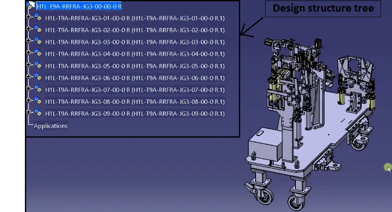
10. Structuring a design tree helps the designer in identifying each part and assembly of a fixture. It uniquely determines the units of a fixture.
Benefits of structure design tree:
- It helps in determining the number of units used in fixtures.
- It helps the designer in defining the clamp units, rest units, etc.
- If a proper structure design tree is not made the components might get mixed up and will take more time for development.
- All standard units are placed at the end of a design structure tree.
- First unit of structure is always the Base unit.
11. UNITS: Units are predefined assemblies that assemble together to form a fixture. These units are classified into two categories Unitized and Non-unitized.
| Simple-unitized | Complex-unitized | Non-unitized |
| Base Unit | Slider Unit | Stands |
| Rest Unit | Dump Unit | Take-out Trolley |
| Fixed pin Unit | Conveyors | |
| Retract pin Unit | Some Grippers | |
| Rough Locator Unit | Turn Tables | |
| Sensor Unit |
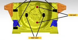
12. FIXED PIN UNIT: A fixed pin unit is a simple unitized unit that has a fixed pin that is used to locate a car panel. The fixed pin unit has a resting clamp, mylars, risers, and blades.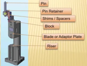
13. Different parts of a Fixed Pin unit are as follows:
- Pin: It is used to locate a car body panel that has a tolerance of -0.15.
- Pin retainer: Pin retainer is used to insert pins in a fixed pin unit
- Shims: These are used to restore stack-up tolerances
- Block: Block used as a support to place shims.
- Blade: Blades are used to stiffen the risers and clamp other components of the fixture.
- Riser: It is used as a standard component to increase the height of units.
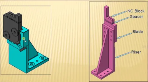
14. REST UNITS: This unit is designed to support the car panel using NC/Mylars etc. Following are the parts of a rest unit:
- Mylar Block: Block used as a support to place shims
- Shims: These are used to restore stack-up tolerances
- Blade: Blades are used to stiffen the risers and clamp other components of the fixture.
- Riser: It is used as a standard component to increase the height of units.
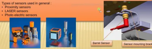
15. SENSOR UNIT: A sensor unit is designed to sense the car panel by using Electrical sensors. The signals from the sensors are sensed in PLC so that the next process can be executed.
Fundamentals to design sensor units:
- Every single loose panel should be sensed which are welded.
- Every panel should be sensed by 1 to 2 sensors depending on the size.
- Every sensor should be mounted in a 3 way adjustable panel.
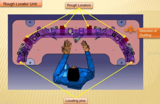
16. Rough Locator: It is used to guide the operator to locate the panel. The following steps are considered while designing a rough locator:
- It should be placed at the edges of a car panel
- They should be placed at same angle as that of car edge at about 2-5 mm distance
- Minimum 10 to 15mm distance must be there between locating pins and rough locators.
- They should be designed with two slots at the bottom in direction of car panel.
17. Base Units: This unit is designed to clamp other units on Base unit.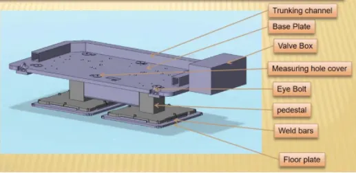
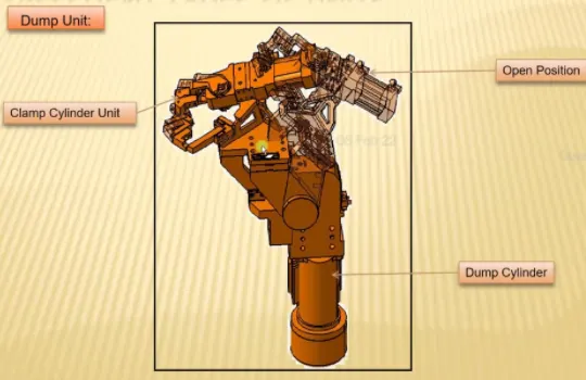
18. Dump Unit: This unit is designed to assemble the panels that are constraint free.
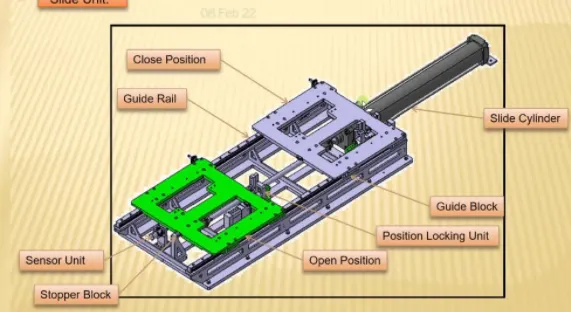
19. Sliding Units: This unit is designed to assemble unit that need to be constrained. It is a replacement for using multiple units.