Week 3:- BiW Fixture Design Methodologies Challenges
1. DESIGN METHODOLOGY
Design methodoly is nothing but the steps folllowed during the concept designing stages of fixture design
design methodology is
1.purchase order
2.inputs from the coustmer
3. percentage completetion criteria
4. design output
PURCHASE ORDER
Purchase order is the order from the coustmer for start of work.
2.INPUTS REQUIRED FROM THE CUSTMER TO START DESIGNING A FIXTURE
The required inputs from custmer are
-functional requirement
-preferrred standard components
- car products
-layout
-egro data
weld study
-standard detailing templates
functional requirements
-welding fixture
-hemming fixture
-checking fixture
-storage racks
preferred standards
1. standard like ABB,NAMS,DESTACO,ZYTRAN,TUNKERS
2. standard parts like riser,l-blocks,retainers,pins
3.components like clamps, cylinders,slides,switches,sensors
4.weldingguns,tip dressers,toolchangers
3.INPUT WE GET FROM CAR PRODUCT
1.GD&T
2OPART LIST
3CAD FILES of car part
4 clamp plan
5 product assembly process sheet
4. CLAMP PLAN
Clamp plan provides the location of pins ,rest, clamp, dumps etc. these positions provided in the coordinates so that the pins and clamps positions are placed at exact points. we should not change the positions without telling to the coustmer.
5.purpose of the layout
layout provides the information of
-flow of parts
-station pitch
-robot station
-accessories like tool changer and tip dresser
-sub assembly links
-platform height
-loading / unloading sequence heights
6. ergo data
- ergonomics refer to the study of human behavior and moments
-ergo data provides information of laoding heights and working safety zone of the operator etc.
- different statandards of ergo data used based on coustmer requirement
- commonly the working height is 800-1000mm and operator reach to the working about 250-300mm
7. wled study
weld study includes
-welding gun details
-weld matrix and weld points
a. geo weld points
b. re-spot weld points
geo spots in red(sphere)
re-spot- green color(sphere)
8. percentage completion criteria
- percentage completion certeria is followed in the design stages and dispatch stages of the welding fixtures
-0-25%- input and concept of the design
-25-40%- concept approval snd simulation check
-40-85%- design freezing and detailing
-85-100%- check and final dispatch
9. DESIGN OUTPUT
- the output is 3d models and 2d drawing of the tools
-unitized tools(multiple units on acommon base require two types of drawing sheets
-key sheet-an index of units and their placements on tool base
-layput sheet- an detailed drawing of individual units to include all of their
components
the out should be complie following points
- approved standard components are to be used whereever possible
-design must be as simple and economics as possible
-design must comply with all current safety and ergonomics requirements
- motion control must be considered on any moving equipments
-designer is responsible to validate clamps and welding guns.
10. STRUCTURING A DESIGN TREE
- structuring a design tree imples to a process where all the assemblies and parts are named in a specific standard different coustmers have different set of stanadards to structure a design tree
-it is an important process which helps us to identify a specific pats or assemblies as to which project,tool or unit it belongs to
-this helps us to avoid the erros during design study, manufacturing, assembly inspection etc
-if the parts or assemblies are not named properly or the design tress is not structured proprly
it will create confusion to understand the design and may create major possiblities of making an error
-namming of a fixture or a unit or a part gives the information as to which project zone or assembly do they belong
-it can helps us to identify the quantiy of items of same type or different types that are being used in assembly.
11. types of units
simple units
- rest unit
-fixed pin unit
-retractable pin unit
-rough locator
-sensor unit
- base unit
complex units
-slide unit
-dump unit
12. FIXED PIN UNIT
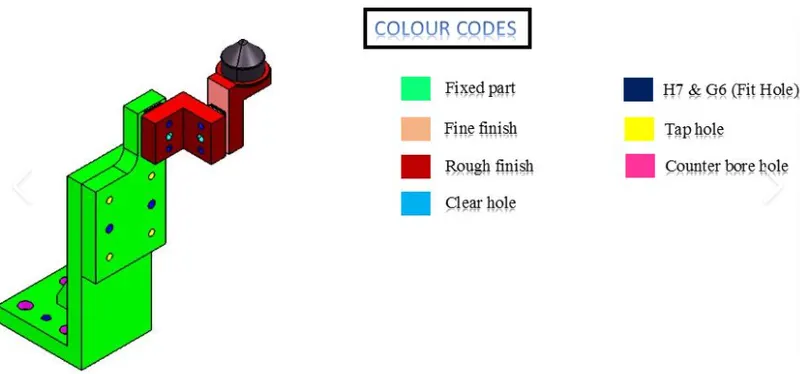
fixed pin unit is a unit designed to locate the car panel using pins and below are the diffrenet parts of a fixed pin unit in general
13. different parts used in the fixed pin unit
1.pin
2. pin retainer
3. blocks
4. shims
5.blade or adapter plate
6. raiser
14 . REST UNIT AND ITS PARTS
a rest unit is a unit designed to rest/ support the car panel using NC blocks /mylar/rest ans below are the different parts of rest unit in general
rest unit parts
1 NC blocks
2.spacer
3.blade
4.raiser
15. fundamental of sensor unit design
-every loose panel which are being welded ina a tool should be sensord
-each panel should be sensed by 1 to 2 sensors depends on the size of panel prefered to be in a diagonal opposite ends of the panel
-every sensor should be mounted in a 3 direction adjustable way in general some major sensor manufactures are IFM , pepperl-fuchs, sick,OMRON etc
types of sensors used
- proximity sensor
-laser sensor
-photo electric sensor
16. ROUGH LOCATOR UNIT
a rough locator is a part designed to guide the operator to locate the car panel on the pins accordingly a rough locator can be standard part or make part
fundamentals of rough locator
- rough locator should placed at the edges of the car panel
- rough locator has be placed in the same angle of the part edge with a minimum distance of 2-5mm from the edge of car part
-rough locator should start guiding the panel before 10 to 15 mm to start of the pin engagement
-rough locator should be designed with entry anle for car part entry
-the slots should be in the direction of car part guiding
17. base unit
a base unit is the unit designed to mount all the other units
clamp unit
pin unit
resr unit etc
of the tool also other parts necessary for a tool ;like pneumatic valve box, trunking cable path WILL ALSO BE MOUNTED ON THE BASE UNIT and below are the some parts of base unit in general
18. dump unit
dump unit is critical unit used to assemble the components which has assembly constraints
dump unit bassicaly a dump cylinder,open position,and a clamp cylinders.dump unit is designed when the car panel conot be assembled in nornal unit and its a complex unit
19. slide unit
slide unit is complex unit.
it is used in space constaints whicle asssemble car panels
it has following parts
-sliding bed
-cylinder open and closed positions
-stopper block
-guide box
-posistion locking unit