Week 2:- BiW Fixture Basics Challenge
1. The project execution activitys are shown below b using flow chart
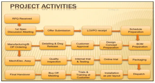
Various activities are there in project actvity gernerally its the process of starting to ending of a project in biw fixture field.
RFQ
RFQ means request for quotation which the coustmer gives the data of his required specifications to study the project before execution .
it includes project time line,commercial offers etc.
1st DISCUSSION MEETING & offer submission
In this activity technical offer,commercial offer,project time line are prepared .
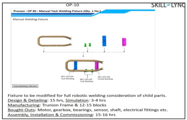
it includes required time for 3d modelling, concept design,simulation,quality check,2d detailing,manufacturing etc.
example-
LOI/PO receipt
Our offer will study by the custmer at the same time he will compare the data with other vendors after that he will releases the LOI/PO with terms and conditions.
schedule preparation
on time delievery is the main requirement from the coustmer so accordingly have to plan when to start and complete the project.
BOM preparation.
Bill of materials a list have to prepare for requirement material for the project.
Design concept and preparartion
design concept is built by studing the data reveived from the coustmer like car panel,3d models,statmodel,standards ,drawings,3d parts according to the process.
coustmers approval
after designing the concept have to review by the coustmers and if it satisfies the coustmer he will approve the concept project will go to further.
Detailling & Drawing release
after the concept design it will go to 3D finish next 2d drawings should be made to release for manufacturing.
manufacturing/ BOP ordering
the 2d drawings are send to manufacturing persons they will start manufacting the parts like myler,plates,frames,blocks and purchase team will purchase the standard parts like cylinders,hardwares,sensors etc.
Mech/elec. assy & Quality inspection
Quality check persons will check the all parts are avialable for the asssembly or not after that assembly will takes place he quality check oersons will check the assembly with the coordinate dimensions as per the assembly 2d drawing sheets.
internal trail and testing
after the quality check approval the internal trails and testing started.they will conduct tests manually the pin unit unit and clamp unit are properly engagging to car panels or not and loading and onlaoding is easy after that all it will go to online trail.
online trail
online trail is two modes one is manual and automated,the control panel,actuators, motors ,safety are tested and calculated the sequence of cycle time for the operations.
packaging
after the all trails are succesfull then it it will go packaging stage here they disassemble the parts and pack them properly because it may damage during transportation and labelling the proper name of the parts
dispatch and installation as per layout
after packing the parts will dispatch to coustmers location by transportation trucks,ships etc. and after reaching the parts to coustmers location assemble and place in the layout and the with respective stations and robot cells
buyoff meeting
after the trails training to the coustmer a meeting between the coustmer and project team for any thing missing in the LOI/PO they will ask project team to do and if they need any extra requiremts or modifications will lead to extra quatation and extra cost.
final handover
after the cousrmers requirements are finished the project technical soft and hard data and manuals submitted to coustmer.
2. Types of joining process
two fundamental options for joining materials and components joints
-mechanical joining
-metallurgical joining
for assemblies llike steel car panels traditional technologies used such as spot welding,arc welding and fusion welding
brazing and soldering adhesive and mechanical fastening used in light weight designs
mechanical fastening
-the joining of materials combinations which cannot be easily welded such aapre painted steels or very dissmilar metals
-the joining of materials in applications where high fatigue life is critical compared to static strength
-the joining of materials where along tool life is of relative importance screws and bolts
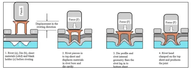
self piercing riviting
-self piercing riviting is high speed mechanics fastening process for point joining sheet materials typically steels and aluminium alloys
-it is a single step technique, generally using a semi--tubular rivit to clinch the sheets in a mechanical joint
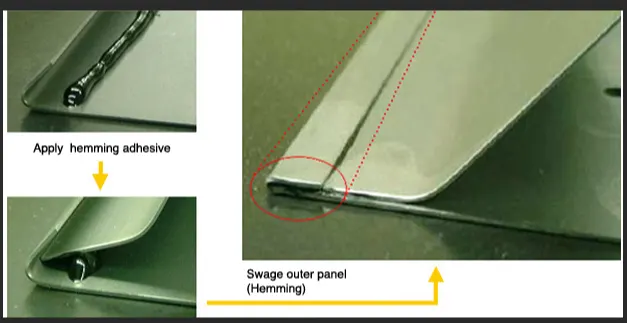
hemming process
-hemming and seaming are two similar metal working process in which a sheet metal edge is rolled over onto self
-hemming is the process in which the edgeis rolled flusg to itself while a seam joins the edges of two materials
Adhesive bonding
-adhesive bonding is used to fasten two surfaces together usually producing a smooth bond
this joining techniques involves glues,epoxies or various plastics agents that bond by evopuration of a solvent or by curing a bonding agents with heat, pressure or time
3. Resistance welding and its applications in automotive industry
resistance welding is a welding technology widely used in manufacturing industry for joining metal sheets and componenets
-the welding is made by conducting a strong cuuernt trough the metal combinantion to heat up and finaly melt the metals at localisized points predeterined by the design of the electrodes and work piece to be welded
-a force is always applied before ,during andafter the application of current to confine and in some apllications to forge the work pieces
resistance welding types
-resistance spot welding
-resistance seam welding
resistance projection welding
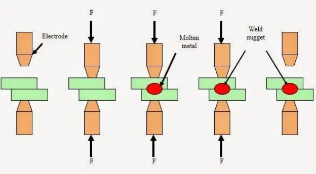
Resistance spot welding
-this process is used for joining sheet materials and uses shaped copper- chromium or zirconium alloy electrodes to apply pressure and convey the electrical current trogh the workpieces
-heat mainaly develops at the interface between two sheets eventually causing the materials beisng welded to melt forming a molten pool, the weldnugget
-the molten pool iscotained bu the pressureapplied by theelectrode tip and surrounding solid metals
Resistance projection welding
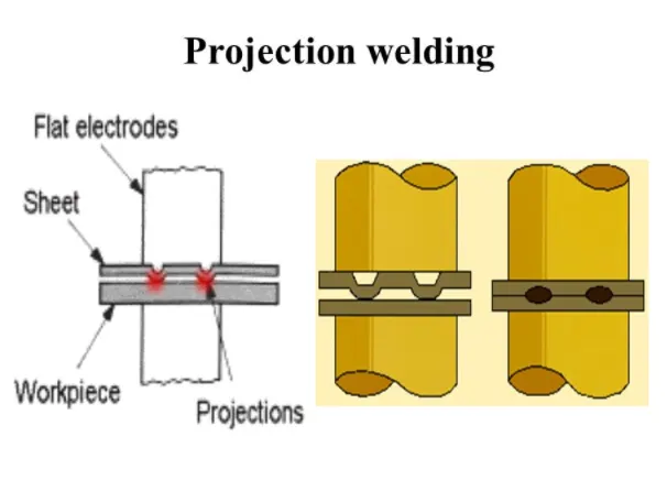
-projection welding is a resistance welding process for joining metal componenets or sheets with embossements by directly appliying opposing forces with electrodesspecially designed to fit the shapes of the workpieces
-the current and the heat gemeration are localized by the shape of the workpieces either with their natural shape or with specially designed projection large determation or collapse will occur in the projection part of the work pieces implying high
Resistance seam welding
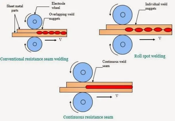
seam welding is a resistance welding process for joining metal sheets in continous ofetn leak tight seam joints by directlyspplying opposing forces with electrodesconsisting of rotart wheels
-the current and the heat generation are localized by the peripheral shapes of electrode shapes
applications of resistance welding
-resistance welding is widely used in making of bolts and nuts
-resistance seam welding used to seal the leakages of bilers and tanks
-flash welding is used to weld the pipes and tubes
applications of resistance welding in automotive industry
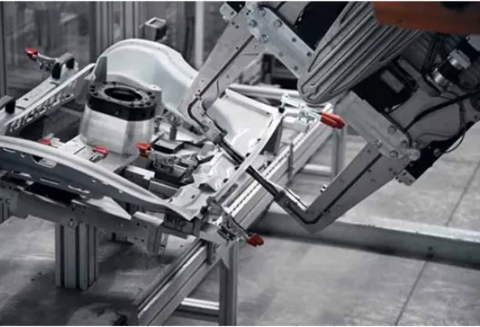
1.resistance spot welding widely used to weld car panels aluminum or steel
2.resistance seam welding used to weld the fuel tanks, boilers etc
4.fusion welding and its applications in automotive industry
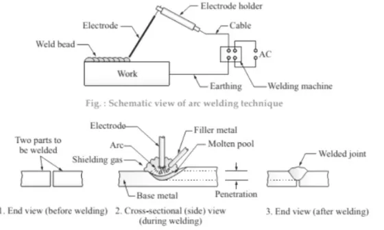
Arc welding
-this process involves either consumble or a non consumable electrode
-an arc produces between tio of electrode and work piece to be welded by use of an AC or DC power supply
types of arc welding
-manual metal arc welding
-Gas-shield metal arc welding (MIG)
-Gas -shield tungsten arc welding (TIG)
-Submerged arc welding
-plasma arc welding
Manual metal arc welding
-MMA also known as shield metal arc welding or informally as stic welding
-the arc is struk betweenthe metal rod and the work piece, both rod and work piece surface melt to create a weld
MIG
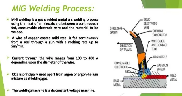
-mig weldining is an arc weldining technique in which a consumable electrode is used to weld two or more work pieces
componenets
-consumable electrode
-inert gas supply
-welding head
-AC or DC power supply
TIG
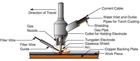
-it is arc weldining method uses non-consumable tungsten electrode to weld two or more workpieces
similar to MIG welding components
-power supply
-filler rod
-inert gas supply
-welding head
application os fusion welding in automotive industry
-MIG weldining mostly used in the removing the failed components in restoring the old cars and modifying the cars
-TIG welding used to weld disimilar metals like nickel,aluminium,copper etc
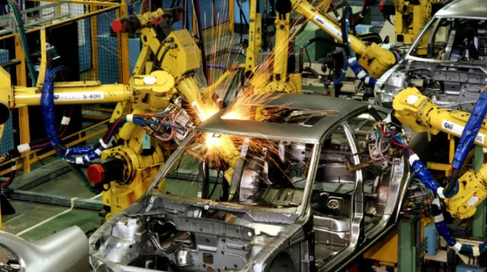
-arc welding widely used in welding the biw,chassis and metal parts.
5. 3-2-1 PRINCIPLE
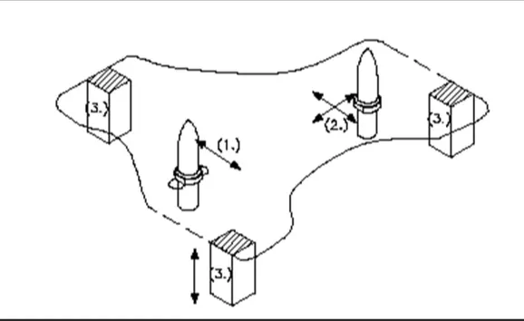
-The best and most efficient method of part location is referd to as the 3-2-1 method
-threee minimum-three locators blocks to establish part plane three locators or suppoters are placed under the work piece, the three locators are usually positioned on the primary locating surfaces this restricts one axial moment downward and four radial moments together, the 3 locators restricts fivedegree of freedom.
-two - round locating pina round hole that defines location in four directions perpendicular to the plane previously established, that restricts 4 axial moments
-one- round locating pin in a slotthat defines two of the direvtions of the otherpi two way that resists two axial movements
6. Body co-ordinates system
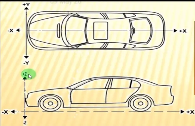
Body coordinate sysytem has been widely used in the automotive industry for drawing of body parts product and process design
a co-rdinate system is a referance consisiting of a set of points , lines and surfaces used to define the position of points in space in either two dimensions
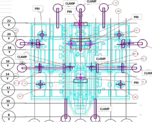
X= FORE & AFTER(F/A) FRONT O LINE
Y= CROSS CAR(C/C) CENTRE LINE COL
Z= VERTICAL( BOTTOM O LINE)
7. BODY PLANES ARE THE REFERANCE PLANES and its essientials
-body plane refereance planes are the referance planes in an automotive car. these planes are used to define the GD&T of all car parts in automotive domine
-body planes are 3 mutually perpendicular imaginary planes these are generally considered to be presen at driver position some times at the engine location or at the front end of the car depending on the custmer
-the measurements from the body planes to the parts are called as bodyline dimensions
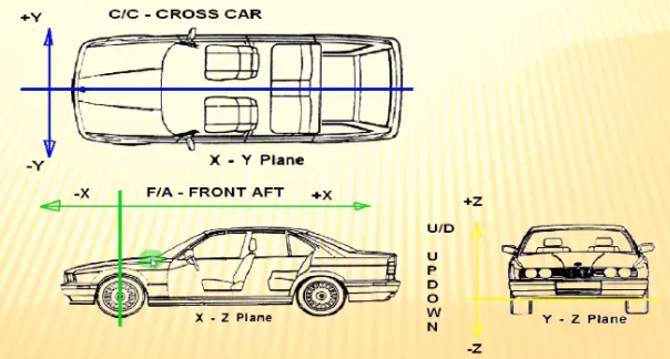
- these body planes are called as
-FOL- FRONT O LINE
-COL- CENTER O LINE
-BOL- BOTTOM O LINE
-measurements along FOL is called as front after(F/A)
-measurements along COL is called as C/C cross car
-measurements along BOL is called U/D UP DOWN
Body dimensions are essential for the reasons stated below
- it defines the exact position of each product in the vechile with respect to a fixed origin
-it ensures flawless design for assembly
-while designing lines all the designs are carried out relative tothe body line
-it assits in easy location of different parts in vechile
-it aims in creating a standard system
-it assists in quality checks