Week 3:- BiW Fixture Design Methodologies Challenges
1) What is Design methodology?
Design methods are procedures, techniques, aids, or tools for designing. They offer a number of different kinds of activities that a designer might use within an overall design process.
Design methodology is nothing but steps followed during concept designing stages of fixtures.
Design methodology categories as below Drawing.
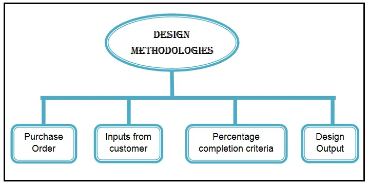
- Purchase order: Purchase order is an order from customer to start the work. A purchase order(PO) is a commercial document and first official offer issued by a Buyer to a seller indicating types, quantities, and agreed prices for products or services. It is used to control the purchasing of products and services from external suppliers. Purchase orders can be an essential part of enterprise resource planning system orders.
- Inputs from customer: When starting the Design we need to understand the customer requirement clearly and efficiently. For those purpose customer sent oral as well as written input to the supplier. Every customer has specific requirements, followed by specific standards like PLP, OLP, 3D &2D Detailing format, standard parts list etc...
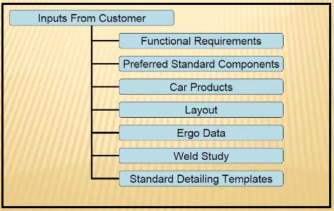
There are some inputs requirement listed below.
- Functional Requirements:
- Preferred Standard components:
- Car Products:
- Layout:
- ERGO Data:
- Weld Study:
- Standard Detailing Templates:
- Percentage Completion Criteria: Percentage completion critical followed in the designing stages and Dispatch stages of the welding fixtures. It’s a basically scheduling and preparing timeline for completion of project work. When we can complete the project each task we define in more detail. It’s a probability to when can complete the entire fixture design.
- Design out Put: Design outputsare the work produced at the end of design efforts, such as drawings, material specifications, or manufacturing instructions. They are what control your design. They must also meet design input criteria defined in the planning stage of your project during design verification.
Output consist 3D models, 2D drawing which is the detailing part, BOM & Stander checklist other related documents. There are some tools which are multiple units on common base are called unitized tools for ex. fixture which includes no. of units on the same base.
They required two types of drawing sheet as follows,
Key sheet- It shows the index of the unit & their placement on tool base
Layout sheet- It is the detailed drawing individual unit to include all their components.
Non- unitized tools which can be completely detailed on layout sheet.
2) What are the inputs required from the customer to start the Design fixture?
The following are the inputs we required from the customer to start the fixture design work.
Fictional requirements:
This basically what kinds of function that fixture design have to perform e.g. welding, Hemming, gluing, fastening, riveting, checking or Storage. This kind of information will be given to us in functional requirement i.e. it serve basic or main purpose like it is used for welding, gluing or checking fixture. So from that design concept generate.
Preferred standards:
The customers want to follow some standards. These standard parts which we can use as it is in our design which saves our project time & money as well.
ABB, NAAMS, TUNKERS, ZYTRAN, DESTACO, FESTO, SMC are some standards.
Some standard parts like riser. L-Blocks, Retainers etc.
Some components like Weld Guns, Tip Dressers, and Tool Changers. Clamps, Cylinders, Switches, and Sensors etc.
CAR Products: Car products like 3d files, read files, as well as to learn and to study what kind of geometrical tolerances and where of PLP points (Principle Locating Points) where we can fix those pinion edge and or the clamping edge and then putting a position.
Car part include
- GD& T
- Part List
- Cad files Car Part
- Clamp Plan
- Product Assembly process Sheet
- GD&T: GD & T Provides Information of information.
Locating pins, Rest, Clamps, Dumps & Slide information of each station. Sequence of openings of Clamps, Dumps & Slide Stroke information.
Part list: Part list is nothing but listing down all parts of assembly. It includes information about the part name, Part number, Tooling revision, Part thickness etc. Assembly is broken down into each & every single part. First assembly has gone between hood inner panels & latches which going to attach next hinge going to attach. So there are different list of assembly we are going to perform. So every assembly will have different fixture unit.
CAD file: 3D file of that car product require from customer it can be STEP or IGES format.
Clamp plan: It provide information about position of clamp unit, pin unit, rest unit etc. this is major input from customer & it should be never be changed without permission of customer.
Product assembly process sheet: It gives detail process of the completion of the part from Raw material to the finished product assembly. It will give detailed plan of component how they welded as well how product is moving from one assembly to other. It’s nothing but flow of the process.
LAYOUT: Layout is plan or arrangement of each process or design of something laid out Such as in BIW fixture design there are multiple Operations are running with all operations space considerations need to take in layout. In layout we get to understand the placing or part movement of one station to next station. Again movement of one zone to next zone. In Multiple operation multiple fixture and Robots are required this all equipments placing in desired positions.
ERGO DATA:
Ergo data is basically involved well manual operators are involved, and every company has different types of standard for aggregate data, so we'll be getting that particular input from the customer so these are the standards that we follow So, this kind of Ergo data we get from the customer.
WELD STUDY:
It includes information of weld gun detail, weld matrix & weld points. There are two types of weld points geo weld point & repot weld point. Geo weld points defines the geometry of part & repot do all other remaining weld points also add strength to geo weld points.
Standard detailing template:
Detailing is 2D representation of 3D part. Customer has standard detailing template. These detailing formats are used for drafting of part.
3) What are the Inputs We Get from CAR Product?
Following input we get from car product.
A). GD & T - Geometric dimensioning & Tolerance of the part for which the fixture have to be designed. GD & T provides information about Locating pins, Rest, Clamp, Dumps & slides information of each station & Sequence & opening of clamps, Dumps & slide stroke information.
B). Part list: Part list is nothing but listing down all parts of assembly. It includes information about the part name, Part number, Tooling revision, Part thickness etc. Suppose first assembly has gone between hood inner panels & latch which going to attach next hinge going to attach. So there are different list of assembly we are going to perform. So every assembly will have different fixture unit.
c). CAD file: 3D file of that car product require from customer. The 3D model file of the car part is given from the customer to study on it. The car part is designed by using 3D modeling software. From this we can get some conceptual idea of the designing of fixture. The model is going to be the base of the fixture design. Below figure illustrate.
- d) Clamp plan: It provides information about position of clamp unit, pin unit, rest unit, dump unit etc. This is major input from customer & it should be never being changed without permission of customer. Clamp plan provide exact location of pins, rest, clamp etc. It is in more detail. It gives exact location in X, Y & Z co-ordinates value to start designing.
- e) Product assembly process sheet: Product assembly process sheet is sheet that gives following detail.
- Part assembly sequence
- Sequence of operation
- Cycle time.
It gives detail process of the completion of the part from scratch to the finished product assembly. It will give detailed plan of component how they welded as well how product is moving from one assembly to other? & this process plan should not be changed without permission of customer. Below figure shows.
4) What is the clamp Plan?
1. Study of process planning document ( Provided it is available)
If you know what are the necessary process documents other wise ask What are the process documents?
- Process document should contain following information , which are necessary to design clamp unit.
- No of sheet metal panels to be welded.
- Total no of spots.
- Welding gun details if its is already recommended by process engineer study it in details like shape and its type(C, X or Y).
- Study the PLP (Principle Location Points) data along with the nearby spot data.
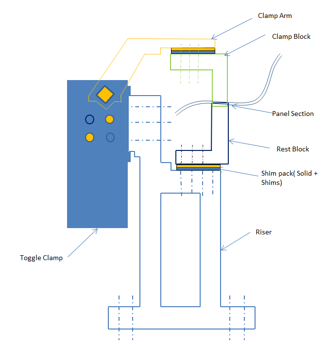
If you are using any specific CAD software as per the customer requirement e.g. CATIA, UG, FIDES understand the customer guidelines how to create the fixture, unit, weldment and base fabrication. Once you have understanding of CAD software methodology to be followed for design of single part, Unit assembly and base then start the design by adding the panel assembly in your fixture or unit assembly.
Take an overview of the working height if you’re having manual welding. For robotic welding also it’s important to see the working height in consideration of the robotic gun, turn table height if manual loading is done.
Put the proper gun at the spot location. If process engineer has gun shape stick to X, C or Y type of gun. Do the proper gun study and place the gun as per the GEO or re-spot decision and operator approach. Once basic gun is placed considering the throat depth and throat gap start building the clamp and rest block at the PLP.
Do not forget to show gun section in the 3D model.
Take a section at PLP either in clamp opening direction or normal direction .Sections should be normal to base. Panel section through X, Y or Z direction passing through PLP.Section will help in finalizing the shape of clamp and rest block. Most importantly used for finalization of gun shape.
Consider following things before deciding the base plate.
No gun arm should touch the base plate. Operator ergonomic while accessing all the spots.
If standard Mylar has to be used (Few companies make standard height and length of steel blank with few holes and dowels for clamping) then select the proper blank size as per the requirement; consider 5 mm above the panel.
Select the clamping cylinder as per the pivot point distance from the PLP. You may choose various cylinder 50 Dia, 63Dia, 80 Dia.as per the requirement (distance of clamp arm from the PLP and no of clamping mounted on each cylinder).
9. Clamp and Rest block creation.
Create clamp or rest block as per the company guidelines .
Many company has size of clamp block as 20x20 mm and no of mounting screws and dowels.
Many use 20x20 size rest or clamp block with one screw and 2 dowels or few use with 2 screw and 2 dowels.
Materials of clamp block and rest block to be decided as per the A class panel or B class.
Most of exterior panel holding Teflon material is used.
Other wise steel is used with heat treatment.
Sometimes Aluminium blocks are also used.
start construction of mounting plate or fabrication structure as per the company standard to make the connection with the base plate.
As per your company or OEM, Tier 1 standard use the different standards mounting risers. Do not forgot to add the 10 mm shim (5mm solid +5mm shim pack, In few companies 3mm shims are used. Make connection plate between rise and Mylar.
For rise please refer the detail blog
If you are combining rough locator or part sensor bracket along with the clamp unit. Take necessary care means distance of rough locator from panel. (I will write in detail about rough locator and sensor bracket in another topic)
Add all the hardware screws, dowels and washer as per the size. Ensure that you can use spanner to open them
Check all the clamp open, gun open position and ensure that there is fouling with panels or any other surrounding units.
Purposefully clamp open position is not shown. You must open the toggle clamp with mylar.And it has be shown in dotted in drawing.
14 Do not forgot to check the screw and dowel removal during maintenance . Check with spanner open position.
5mm thk shim and 5 mm shimpack is used.
Single panel clamping shown (for simplicity) . Means single panel CAD data will be used to cut clamping and rest mylars.
- What is the purpose of a layout?
Plant layout is plan of an optimum arrangement of facilities including personnel, operating equipment, storage space material handling equipment and all other supporting services along with the design of best structure to contain all these facilities. An overall objective of plant layout is to design a physical arrangement that meets the required output quality & quantity most economically.
It shows all the objects of manufacturing line like robots, Fixtures, Racks etc. & also shows the reach ability of the robot to the fixtures also called the swept area of the robot (indicated by circle around robot). It also shows the constraint of space or the space available for the fixture that we are designing.
Layout provides information about flow of parts, station pitch, robot station, accessories like tool changer & tip dresser, sub assembly links, platform height, loading & unloading sequence.
- What is ergo data?
Productivity is a powerful tool to improve the standards of living of people & to enhance the quality of work life (QWL). Ergonomics is concerned with man & his working conditions. Ergonomics aims at providing comfort & improved working conditions so as to channelize energy, skills of workers into consecutive work. This account for increased productivity, safety & reduces fatigue. Ergo data is given when manual operator involved to do operation, so this input is given regards how their standard of ergo data is. Ergo data provides information of loading height, working safety, zone of operator etc.
The final assembly of an automobile involves tasks of complex nature. These processes are on the least priority for automation. Manual labor is best suited for assembly operations with the aid of minimal level of automation. All the processes have to be improved continuously in order to reduce the costs and increase productivity.
The workers attain various postures; exert force and works continuously in cycle time to accomplish the assembly task. Working along automobile assembly lines is characterized by repetitiveness.
Ergo data is studied to identify and quantify ergonomics working postures that contributed to the serious development of muscle skeletal injuries and thus investigated possible contributory their related causes. Below figure show ergonomically correct seating position while working.
Below fig show ergo data provided by customer.
- What do you understand by weld study?
It includes information of weld gun detail, weld matrix & weld points. There are two types of weld points geo weld point & respot weld point. Geo weld points defines the geometry of part & repot do all other remaining weld points also add strength to geo weld points. Weld study consists of spots in case of spot welding fixture that gives us the position of spot in the form of coordinates. It is most important input that we get from customer. These are the points where the panel is welded. The spots can be geo spots or respots shown in figure.
The front door inner panel and side bracket of GM sedan car are to be spot welded as shown in Figure 1. The previously spot welded inner panel assembly is then welded with the cross bracket as shown in Figure 2. The work cell and modular fixture designed must be compatible for both the assemblies to be spot welded.
Weld spots for each weld assembly are highlighted in Figure 1 and 2 as WP1, WP2, and WP3 and so on. Weld points are the locations on which spot welding will be carried out on the automobile sheet metal components. The Weld points forms the base for fixture design, the clamping plan & locating plan are done based on the weld spot distribution. The weld spots for Front door inner panel - side bracket assembly are located as shown in Table 1 with respect to the body line of car.
The weld spot locations with respect to the body line of car are as shown in Table 2.
- What are the criteria for percentage completion in the designing stage? Explain it in detail.
- Percentage completion criteria are followed in the designing stage & dispatch stage of welding fixture. The percentage completion criteria contain the current status of a task, expressed as the percentage of the task's duration that has been completed. You can enter percent complete, or you can have Project calculate it for you based on actual duration.
- It is followed in designing stages & dispatch stages of the welding fixture.
- It ensures that how much task that we have decided to complete within the stipulated time is complete or not & how much of it is rest to complete & whether it is going to be complete or not in given time.
0-25%- Input & concept design:
This is initial stage of project. Input data provided by customer like functional requirement, customer standard etc. & after studying those inputs the concept of fixture design is created. After completion of these tasks about 25% of work completed.
25-40%- Concept approval & simulation check:
As concept of fixture design is created & simulation checked it is sending for customer approval. Customer will study all simulations & gives his approval. If there are any changes required, then it has to do accordingly & again submit for approval. This concept design approval from the customer after study of simulation contributes only 15% of total design work. But with completion of this task 25-40% works completed.
Design freezing & detailing- 40 to 85%:
This phase involve design freezing after approval of concept design. Freezing means finalizing concept design. Then next step is detailing as per customer standard template. With completion of this stage, almost 85% of work is completed in designing stage.
Check & final dispatch- 85 to 100%:
After detailing the quality checking team starts inspection of all the data & it will dispatch to the customer if it is ok as per customer standard. If there is in error in drafting it will create issue or mistake in manufacturing stage.
Thus, a percent completion criterion helps us to know where we are in design process.
- Brief about “output” in design?
- It includes data to be given to customer after completion of design stage. The output is 3D models & 2D drawings of the tool.
- In the fixture element design output contains detailed design of locators, detailed design of clamps, detailed design of supports, positions of locators, positions of clamp, positions of supports if any, type of locators, types of clamp, types of supports, clamping forces & supports.
- There are two types of tools in fixture design unitized tool & non unitized tool
- In unitized tool there are multiple units on common base for e.g. geo fixture, respot fixture, checking fixture, hemming station etc. Unitized tools require two types of sheet key sheet & layout sheet. Non- unitized tools that can stand alone & can be detailed completely on a layout sheet. E.g. Rack, take out trolleys, turn tables, grippers etc.
- Key sheet: an index of units & their placement on the tool base. Key sheet shows placement & location of that particular unit on tool base where exactly & exact position of tool base. Key sheet is showing orthogonal or isometric view of that entire component.
- Layout sheet: A detailed drawing of individuals units to include all of their units. Layout sheet is detail drawing of that particular tool where we are going detail of component. Grid view in below figure tells that where exactly component is located in geometry. This is also helpful in CMM inspection of fixture.
- The output should compile following point-
a). Approved standard parts should be used wherever possible. This saves lots of time, effort & economical.
b). Design should be as simple & economical as possible. Geometry is complex then fixture designs complex but approach is trying to design as simple as possible.
c). Design must comply with all current safety & ergonomics standard.
d). Design must provide for controlled & damage free handling of product. It should not damage other part.
e). Adequate error proofing provision must be incorporated in each design by providing proximity switches, rough locators etc. Proximity switches are basically sensors which tells part is present or not in fixture. Rough locators work as pokayoke to guide entire panel orientation.
f). The weight of moving part must be kept to minimum while maintaining maximum strength. Weight of moving component kept as minimum as possible but it shouldn’t compromise on strength. There is balance between these two things.
g). Frames & structures are to be simple & sturdy.
h). Design clearance & accessibility for routine maintenance & service. Fixture need to maintain after certain period of time so it is easily accessible for maintenance.
- i) Motion control must be considered on any moving component. Adequate to control the motion of component like slider, clamp arm so that it does not give any vibration & stays on particular limit by use of hard stopper, shock absorber.
j). Designer is responsible to validate all clamps & weld guns. So that all clams & gun should perform its function without fail.
- What do you understand by structuring a design tree? How does it reduce error during the design process?
Structuring a design tree implies process where all the assemblies & parts are named in specific manner. Different customers have different set of standard like how to structure a design tree? So they will be give standard template based on that design tree structured, which helps us to identify specific part of assembly. It specifies the Project number, station number, unit number; part number of each component so that it is easy to identify the parts.
It is an important process which helps us to identify a specific part or assembly as to which project, tool or unit, it belongs to.
This helps us to avoid error during design study, manufacturing, assembly, inspection etc.
If parts or assemblies are not named properly or the design tree is not structured properly, it will create confusion to understand & create major possibilities of making an error.
Naming of a fixture, a unit or a part gives the information as to which project or zone or assembly they do belong.
It can help us to identify quantity of items of same type or different types that are being used in assembly for e.g. bolt. It actually tells you how many bolts are particularly required in that assembly or unit. Below figure shows design tree structure properly & component shown in key sheet. Each unit has a separate name.
Structuring the tree is important as it is easier to differentiate the manufacturing parts from standards, bought outs and hardware’s. Order of tree from top to bottom is: designed or manufacturing parts, after those standards parts from customer, bought outs parts are at bottom as shown in below figure. Every design tree base unit is first unit.
As shown in above figure naming is done as
H1L-T9A: Project name.
RRFRA: Panel name rear panel.
JG3-: Jig no.3
00-00: Unit no, part no respectively.
0R: Right side panel.
11) What are Units? Mention 5 types of units.
- A unit is a device that has a specified function, especially one forming part of a complex mechanism.
- The BIW fixtures are the assembly of different units which are designed to fulfill different purpose.
- The unit has the specified function like resting the panel, clamping the part, locating the part etc.
- According to the 3-2-1 principle of fixture design the units are designed to locate & clamp the car panel to its specified position in fixture while operation is going on.
- In the following the different units are showed by different color.
UNITS IN FIXTURE DESIGN
The fixture design involves huge number of parts and with respect to their function they are classified into different units. The units are classified
Non-unitized tool have no process functionality and will used to support the process fixtures Egg: Stands, Conveyors, turn Tables
Unitized Tools are the process units that forms simple and complex parts of the fixture design
The types of Units are
- Base Unit
- Resting Unit
- Clamping Unit
- Pin Unit
- Sensor Unit
- Dump unit
- Slide Unit
- Rough locator
FIXED PIN UNIT
Fixed pin unit is a unit designed to locate the car panel using pins. The different parts in fixed pin unit are
- Pin: Pin is the holding device that touches the panel. The shape of the pin depends upon the mounting hole of the BIW Panel and is designed to have very close tolerance
- Retainer: Retainer is a block which supports the pin.
- Shims: These are parts that are mounted on two way locators to adjust the coordinates of the pin
- Block: Blocks are mounting space for rest of the pin unit
- Adaptor Plate
- Riser: Riser are used to lower and rise the pin unit
PURPOSE
Pin units are essential part of the fixture that is used to restrict the rotational degree of the panel and lies in the exact coordinate. Shims are given in two coordinate directions to negate the stacked up tolerances the entire fixed unit is placed in a block unit that is supported by the riser.
Retractable Pin unit are used for similar purpose as fixed unit but the difference is Pin will be supported by a retractable cylinder. The main objective of the fixed pin unit is to maintain the specified coordinate distance specified and has to pass the quality test done by the CMM Machine
REST UNIT: Rest Unit are used to support the car panel using NC Blocks/Mylar/Rest
- The rest unit supports the pin, retainer and helps the fixture to hold the panel rigid during the vibration. The resting unit.
- The Risers are used to adjust the height of the fixture based on required coordinates
- The Mylar’s/NC Blocks helps in holding the fixture parts rigid
- Blades are used for mounting other parts like cylinder, arms etc,
CLAMP UNIT
Clamp unit is used to clamp the car panel with Mylar by using a cylinder. The clamp has two positions; opening condition and closed condition. The clamp unit are allowed to open to a specify angle and operated by pneumatic cylinder
SENSOR UNIT
- Sensor unit are used to sense the car panel by using electrical sensors and the signal will be fed to the PLC
- The main purpose of using a sensor panel;
- To detect the loose panel which are to be welded
- They are used to sense the orientation and size and also used to activate the pneumatic cylinder based on different sequence
- The types of sensor used are Proximity sensor, LASER Sensor, Photo Electric Sensor.
ROUGH LOCATORS
Rough Locators are used to guide the operator to locate the car panel on to the pins accordingly and it can be a standard part is made part. Also a poke yoke purpose.
Fundamentals of Rough Locators Design
- Rough locator should be placed at the edge of the car panel
- It has to be placed at the same angle of the car part edge with a minimum distance of 2-5mm from the edge of the car part and should have adequate gap which prevents from damaging during loading and unloading
- Rough Locator should guide the car panel in the pin arresting direction
- It should be designed with entry angle for cart part entry and should be designed with two slots to mount panel and for easy adjustments.
- Rough locators should start guiding the panel before 10-15mm to the start of the pin engagement
BASE UNIT
Base units are used to mount all other units of the tool along with necessary tool units such as pneumatic valve box, trunk cable path will also be mounted on to the base unit
- Valve box are the parts in base unit that supplies air to the cylinder and has solenoid valves to regulate the flow
- The base unit is mounted on the Floor plate using pedestal stand that is welded with the plate.
- Eye bolts are used to lift the base unit
DUMP UNIT
Dump unit is a complex design assembly and is used during some constraints where normal mounting of pins, clamp, rest are not desirable.
SLIDER UNIT
Slider unit is another complex fixture design which is used during space constrains and helps to position the fixture
And help to position the fixture
Slider Unit
Based on the type of the guide ways, type of the prime movers used the Slider units are classified as Hardened Guide Way
LM Guide Way
Manual Slides
Hydraulic Slides
CNC Slides
The frictionless guide ways are usually used to position the car part and has cylinders, stoppers, sensors, locking unit
Slider for movements
For Instance, Slide units are used for moving the weld guns from one point to the other when robotic weld guns are not used
Enlarged view of Weld spot
- Describe fixed pin units & their purpose?
Answer:
Fixed pin unit: It is unit designed to locate car panel using pins. It is unit pin is already fixed it cannot moved & below are different parts of unit in general. Fixed pin unit basically have pin, pin retainer, shims/ spacers, block, blade or adaptor plate. Pin retainer support that pin.
Every pin unit will have two directional shims. The block is used to mount entire pin unit. Shims are used to avoid stack up tolerance while assembling entire component. Shims are come in pack of 0.1, 0.2 & 0.5 mm.
Purpose of fixed pin unit: Pin is most important part of fixture & used to restrict rotational as well as translational degrees of freedom of that particular component. Purpose of fixed pin unit is to fix the panel translation motion along two axes and to prevent rotation of panel in the axis of panel.
It supposes to have exact coordinate for it to get fix. Suppose it will move by 0.1 to 0.2 mm from its original positional then entire assembly will not happen or get rejected.
- What are the different parts of a fixed unit?
Answer: Fixed pin unit consist of riser, blade, block, shims or spacer, pin retainer & pin. All parts are described below.
A). Riser: Risers can be of L-type, welded or square tube or frame type. These are basically manufactured parts are used to give height to assembly.
- b) Blade: Blades are plates attached to riser. Other part likes cylinder, arms etc are mounted on the blade. Chamfer is given here to strengthen the blade. Two Dowel Four Hole arrangements are used to butt blade to the riser.
c). L-Blocks: L Block is used just to provide the necessary shimming for adjustment. In case of mounting an L block, we should check bolting access as there is already a bolt to tight the pin. Hence, clear hole should be given from L block.
d). Shims/spacer: In fixture, we are providing tolerance to each part mostly manufactured. Those tolerances tend to stack up & reflect together. In order to avoid that we use shims so we can easily adjust after assembly so whatever stack up there we will rectify it through shims. Shims come in thickness of 0.1, 0.2, 0.5 etc.
e). Pin: It is used for the location purpose of the panel. Standard Pins should be used as far as possible and the lengths of pins should be reduced to maximum possible. Generally, pin diameter should be cylindrical grinded to maintain its dimension accurate. Usually two locating pins are enough to properly locate the work piece on one plane. There are dozens of styles of locating pins that can be utilized in a design. We will explain the structure and show an example of how each style can be applied. The different types of Standard Pins are as follows:
Round Pins: These can be Screw secured (PNRS) or Grub Screw secured (PNRG) or Thread secured (PNRT) for Prototype build only. One of the most common pins is a stepped pin with either small or large head.
Diamond Pins: The Diamond Shape is a critical feature that helps with machining inaccuracies and smoother locating operation. When two round head pins are installed onto one plate, the distance between two mounting holes must be extremely precise and even then, the work piece will not be placed on the base as easily as it would with the use of a diamond shape pin. These can be Screw secured (PNDS) or Grub Screw secured (PNDG) or Thread secured (PNRT) for Prototype build only.
f). Pin retainer: Pin retainer support that pin. Pin Retainer is designed to hold the pin in its place and is also used as a rest for the pin. A counter hole is drilled on which pin is fit.
- What is the purpose of making a rest unit & describe its parts?
Answer:
Rest unit: Rest unit is unit designed to support car panel using Mylar/ NC block/ rest. Component is rested only, no upper clamp or force applied there. It is the simplest unit to design because it has fewer parts to design & the purpose is only resting of the car panel.
Because of this simplicity the rest unit is combined with other unit to reduce the cost of the overall project. It can be combined with clamp unit to clamp as well as to rest the car panel. It can be combined with locating unit to locate as well as to rest the car panel. Also locating, clamping & rest unit can be combined together in one unit to reduce cost. There is no cylinder attached to it. It has rest Mylar, blade & riser & below is different parts of rest unit. Rest unit is also divided into simple support unit, multiple support units & retractable support unit.
A). Mylar/ NC blocks/ Fingers: These are parts are used to hold panel. They are globally called as Mylar. Top side Mylar is called as clamping Mylar & bottom side is called resting Mylar. Every clamping Mylar should have resting Mylar. It is jaw type. It prevent panel from deforming while welding. It is hardened to increase its wear strength.
b). Riser: Risers can be of L-type, welded or square tube or frame type. These are basically manufactured parts are used to give height to assembly. It is machined at mounted ends only to save cost.
c). Blade: These are plates mounted on the riser. Other parts like cylinder, arms etc are mounted on the blade.
d). Shims/spacer: In fixture, we are providing tolerance to each part mostly manufactured. Those tolerances tend to stack up & reflect together. In order to avoid that we use shims so we can easily adjust after assembly so whatever stack up there we will rectify it through shims. Shims come in thickness of 0.1, 0.2, 0.5 etc.
- What are the basic fundamentals to design a sensor unit?
Answer:
Sensor unit: It is designed to sense car panel using electrical sensor. This signal the sensor will be fed to the PLC & so next process will be executed. Sensor unit are used actually in sensing whether panel are there or not or particular component are there or not. Suppose there are 9 no’s of par require for assembly then we have that no. of sensor at least. Whenever operator manually assemble entire component they do the process like fastening, gluing. The sensor will show that particular component is there or if component is missing it will give an error.
Fundamental of sensor unit design:
- Every signal loose panel which are being welded in tool.
- Each panel should be sensed by 1 to 2 sensor depends on size of panel, preferred to be in diagonal opposite ends of panel.
- Every sensor should be mounted in 3 directions adjustable way in general.
- Some major sensor manufactures are IFM, Pepperi-fuchs, SICK, and OMRON etc.
Types of sensor used in general.
Proximity sensor- It has sensing range 5 to 6 mm. It is based on magnetic field principle. A proximity sensor is a sensor able to detect the presence of nearby objects without any physical contact.
A proximity sensor often emits an electromagnetic field or a beam of electromagnetic radiation (infrared, for instance), and looks for changes in the field or return signal
Laser sensor: It has sensing range is farther away from proximity sensor.
Photo electric sensor: A photoelectric sensor is equipment used to discover the distance, absence, or presence of an object by using a light transmitter, often infrared, and a photoelectric receiver. They are largely used in industrial manufacturing. Below fig shows.
- What is a rough locator unit & what are the basic fundamentals to consider while designing it?
Rough locators: Rough locators are usually used in loading & unloading of particular part. It is also used to guide. Rough locator unit is apart designed to guide the operator to locate car panel on the pins accordingly. They have slot for adjustment. A rough locator can be of std. part or mate part. It is also work as poke yoke.
Fundamentals of rough locator design.
- Rough locators should be placed at the edge of car panel, which it has to guide using locating pins one can easily restrict movement of entire car panel.
- Rough locator has to be placed in the same angle of the car part edge with minimum distance of 2.5 mm from the edge of car part, so it should no damage panel.
- Rough locators should guide the panel before 10 to 15 mm. to the start of the pin engagement.
- Rough locators should guide the panel in pin arresting direction in general.
- Rough locators should be designed with two slots to mount for easy adjustment. (in general)
- The slot should be in the direction of car panel guiding.
- What is a base unit & describe its parts?
Answer:
Base unit: A base unit is the unit designed to mount all other units (clamp unit, pin unit, rest unit) of the tool, also other parts necessary.
For a tool like pneumatic valve box, trucking cable path will also be mounted on to base unit & below are the some part of base unit in general.
a). Base Plate: Base Plate is a machined plate made of steel or Aluminum of thickness 25mm to 40mm on which the holes are drilled to mount different units like rest units, clamp units, pin units etc.
b). Pedestal: Pedestal is a part or an assembly (welded structure) that joins the base plate to the floor plate. Pedestal can be a standard part or a make part, depending on size and height of fixture. Standard pedestals are available in different heights. Pedestals are also available in different inclinations. Depending on the size of base plate; the number of pedestal for a fixture can vary for load distribution
c). Valve box: Pneumatic valve box includes solenoid valve which supplies air to pneumatic cylinder & their coil. Sometimes a bunch of valve is mounted is called as valve blank.
d). Trunking channel: Trunking channel which mounted on base is used to guide all electrical cable, pneumatic pipe. Base support entire fixture unit. Trunking Channel is a duct that carries all the electrical and pneumatic connections (wires and pipes) for units of the tool. It has a thickness of few millimeters.
e). Eye bolt: They are used to lift entire base unit, pedestal to support base plate.
f). Floor plate: They are used to mount entire unit & a leveling arrangement such as leveling bolt & pad are provided to base unit to level the entire unit.
- What is a dump unit & what are its functions?
Answer:
Dump unit: Dump unit is where you assemble component if you have certain constraint. Here you will have clamp unit, pin unit attached & panel will be assembled. So if you have certain constraint you cannot assemble in normal way. Dump unit use in different way. It has dump cylinder & complex design. It consists of dump cylinder to perform the operation of clamping & unclamping car panel. A dump unit can have more than one cylinder to perform such operation. The first cylinder dumps the assembly carrying clamp Mylar’s, pins and then this assembly performs the required operation. In this unit, we should make sure that in the open position of panel, we should be able to remove the panel. Below fig show dump unit.
- What is a slide unit? Mention where slide units are commonly used
Answer:
Slide unit: Sliding unit consist of sliding cylinder. It slides between open & close position. At the end it has shock absorber & after that hard stopper. It has guide rail. It uses sliding mechanism. It also has position locking unit for maintenance purpose doesn’t allow to move entire unit & sensor unit to sense entire component reached at either side or not & stopper block to control moving. When cylinder opens position locking mechanism unlock the panel. Then entire panel move to open position using frictionless guide block. Guide block need to lubricate periodically.
Sliding unit are basically use in places where you have certain constraint, space constraint. Sometimes, there are too many small panels near each other and there is not enough space as each panel requires resting, location using 2 pins, clamping and sensing. This becomes even more difficult when panel is at angles. To solve this problem, a slide unit mounts rest, clamp or pin unit or all of them on a slide using guide rails, guide blocks, a cylinder, locking mechanism, stop blocks and sensors. When a particular panel is to be welded, this slide moves forward, fixes the panel and on completion of operation, slide moves back and gets locked at its position. Similarly, the same is done for other panels.