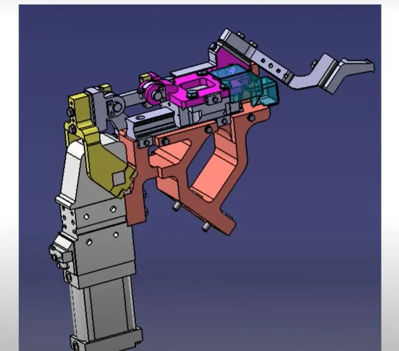
Week 3:- BiW Fixture Design Methodologies Challenges
Q-1 What is design methodology ?
- Design methodology refers to the development of a system or method for a unique situation. Today, the term is most often applied to technological fields in reference to web design, software or information systems design. Various degree programs involve design methodology, including those in the graphic and digital arts. Read this article to learn more about what design methodology is.
Components of Design Methodology.
- The key to design methodology is finding the best solution for each design situation, whether it be in industrial design, architecture or technology. Design methodology stresses the use of brainstorming to encourage innovative ideas and collaborative thinking to work through each proposed idea and arrive at the best solution. Meeting the needs and wants of the end user is the most critical concern. Design methodology also employs basic research methods, such as analysis and testing.
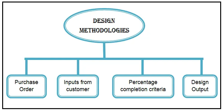
Purchase order : The purchase order of PO is an official document issued by a buyer comminting to pay the seller for the sale of specific product or service.
Inputs from customer : Inputs that need to have with design engineer which is provided by the customer to start the project which are BOM , CAD panel data , 2D drawing of assembly , sheet metal
panek thickness , spot detail , weld information , PLP , cycle time & all clamping and cylinder standards etc.
Percentage completion criteria : It consist planning of completion the project. How much days the project will take to complete.
Design output : Output consist 3D models , 2D drawing which is the detailing part , BOM & other related documents. They required two types of sheet : Key sheet , Layout sheet.
Q-2 What are inputs required from the customer to start designing a fixture ?
The inputs from the customer are:
- Functional requirements.
- Preferred Standard components.
- Car Products.
- Layout.
- Ergo Data.
- Weld Study.
- Standard Detailing Templates.
1. Functional requirments :
- It is the basic requirement which defines the function of the fixture whether it is being used for welding , hemming , checking fixture or storage racks. Depending on this the design consideration
are going to change while designing the fixture.
2. Preferred standard components :
- There are some prefer standards that every company follow , they may varies depending on which one the company follows.
- These parts which we can use in our design , which saves project time & money as well.
- ABB , NAAMS , TUNKERS , ZUTRAN , DESTACO etc.
- Some standard parts like riser , L blocks , retainers etc.
- Some components like cylinder , clamps , switchs , sensors etc.
3. Car products :
- It includes following inputs from the customer.
A) GD & T : Geometric dimensions & tolerencing of the parts involved in the design. GD&T provides information of locating pins , rest , clamps , dumps & slides information of each station.
B) Part list : This is list of parts which are going to assembled in the fixture.
C) CAD files of part: The 3D model file of the car part design by using modelling software is given from the customer.
D) Clamp plan : This is the clamping plan of the part while doing the operation. It is very important input from the customer it provides locations of pins , rest , clamps dumps etc.
E) Product assembly process sheet : It gives detail process of completion of the part from scratch to finished product assembly.
4. Layout :
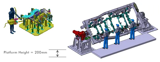
- Layout provides imformations of flow of parts , station pitch , robot station , tool changer , tip dressers , platform height , sub assembly links.
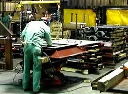
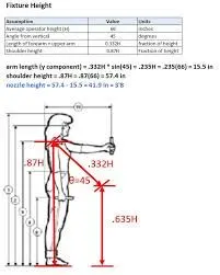
5. Ergo data :
- It is study of human behaviour & movements during the assembly work.
6. Weld study:
- It includes the study of weld gun is used for the operation depending on the size of part , thickness of the part etc.
7. Standard detailing templates :
- Every customer have there standard of detailing & the templated which are used for 2D drawing & detailing.
Q-3 What are the inputs we get from " car products " ?
- Following are the inputs we get from car products :
A) GD & T : Geometric dimensions & tolerencing of the parts involved in the design. GD&T provides information of locating pins , rest , clamps , dumps & slides information of each station.
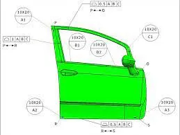
B) Part list : This is list of parts which are going to assembled in the fixture.
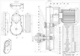
C) CAD files of part: The 3D model file of the car part design by using modelling software is given from the customer.
D) Clamp plan : This is the clamping plan of the part while doing the operation. It is very important input from the customer it provides locations of pins , rest , clamps dumps etc.
E) Product assembly process sheet : It gives detail process of completion of the part from scratch to finished product assembly.
Q-4 What is clamp plan ?
- Clamp plan provides the informtion of location of pins, Rest units, clamp unit, Dumps etc. It is the important input from customer. The clamp plan/position should not be changed without the knowledge of customers.
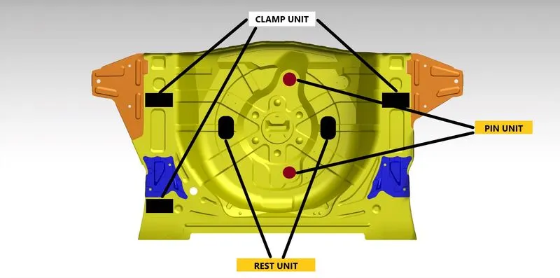
- Clamp plan is very important input from the customer the clamping plan of the part is the plan which defines location of clamps while doing the operation to ensure the geometry of the assembly.
- It provides the information regarding to the locations of pins , rest , clamps , dump etc. The co-ordinates are also mentioned in the clamp plan , so the design team can take the co-ordinates directly
& start designing of the fixture.
Q-5 What is the purpose of layout ?
- Fixture layout depicts the arrangement of locators and clamps around the workpiece. The position of the locators and clamps is one of the major factors which cause the elastic deformation of the workpiece during machining.
- The optimization objective is to search for a fixture layout that minimizes the maximum elastic deformation of the machined surface for the entire cutting process. A finite element model of the fixture- workpiece system calculates the elastic deformation of the workpiece due to fixturing forces.
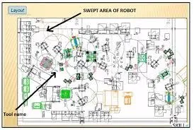
- Layout provides imformations of flow of parts , station pitch , robot station , tool changer , tip dressers , platform height , sub assembly links.
Q-6 What is ergo data ?
- Following human factors should considered while designing seat:
Riding comfort
Visibility
Location
Ease of control
H point
- Occupant space envelope creation:
By considering above points envelope can be created and analyzed the comfort for occupants.
- Terms used in Ergonomic study:
Transverse plane: means a vertical plane perpendicular to the longitudinal plane of the vehicle
Longitudinal plane: means a plane parallel to the median longitudinal plane of the vehicle
R point: Seating reference point represents seating position
Theoretically hip point used while designing a vehicle and more specifically relative location of the dummy's
hip point, when the seat is set in the rearmost and lowermost seating position
H-point (Hip point):
This pivot center of the torso and thigh of the three-dimensional H-point machine used for actual H-point
determination. It is located on the center-line of the device which is between the H-point sight buttons on
either side of the H-point machine.
Recommended H position:
H point, as defined by its co-ordinates, lies within a square of 50 mm side length with horizontal and vertical
sides whose diagonals intersect at the "R" point
Design set back angle:
ranges from 10° to 30° depending on the vehicle type
Recommended 15 degrees
Q-7 What do you understand by weld study ?
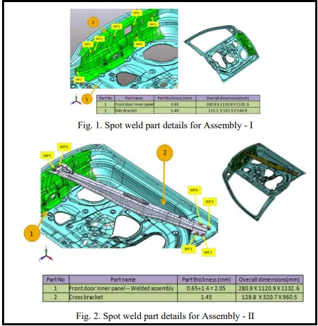
- Welding is predominately used in automobile industries & requirements for fixtures that ease the welding process is a continous development task in any industry.
- Car body in white (BIW) is complicated steel structure including 300 - 500 sheets with complex shape & are assembled by mean of welding in high rhythm through 55 - 75 robotic work stations.
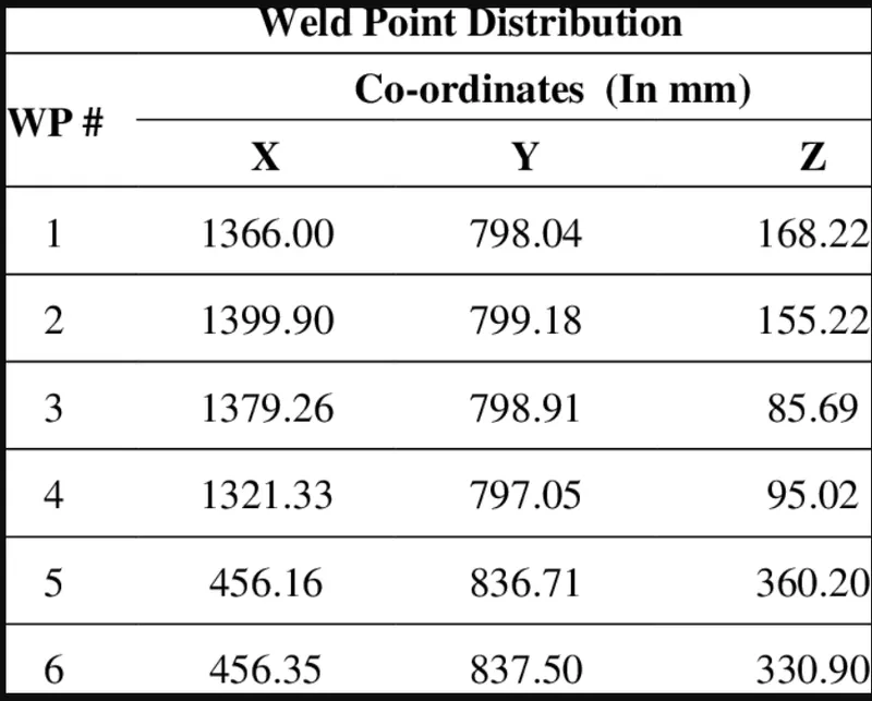
- The foremost step taken before starting the design of welding fixture is to arrive at the spot weld locations. The location & orientation of other critical units of the fixture including clamps , locators etc
are decided based on weld spot distribution.
Q-8 What are the criteria for percentage completion in the designing stage ? explain in detail.
- It consist planning of completion the project. How much days the project will take to complete.
- The percentage is followed in the designing stages & dispatch stages of welding fixture.
- It helps us to identify the stages in the project like how much the project is completed & what are further stages are in pending to complete which helps us to complete the project in the given time &
date.
- The percentage criteria are divided into four stages :
1. Input & concept design
2. Concept approval & stimulation check
3. Design freezing & detailing
4. Check & final dispatch
1. Input & concept design.
- If the project is in input & concept stage it will around 0 - 25 % completion stage.
- The design inputs from the customer & after studying those inputs the concept fixture design are created.
2. Concept approval & stimulation check.
- It will around 25 - 40 % completion stage.
- The concept design approval from the customer after study of stimulation.
3. Design freezing & detailing.
- It will be around 40 - 85 % of completion stage.
- After the stimulation result if no any changes are required then the design is freezed. After freezing the 2D drawing which is the detailing part is started.
4. Check & final dispatch.
- It will be around 85 - 100 % of completion stage.
- After detailing the quality inspection team start checking all the data & it will be dispatch to the customer if everything is ok.
Q-9 Brief about " output " in design ?
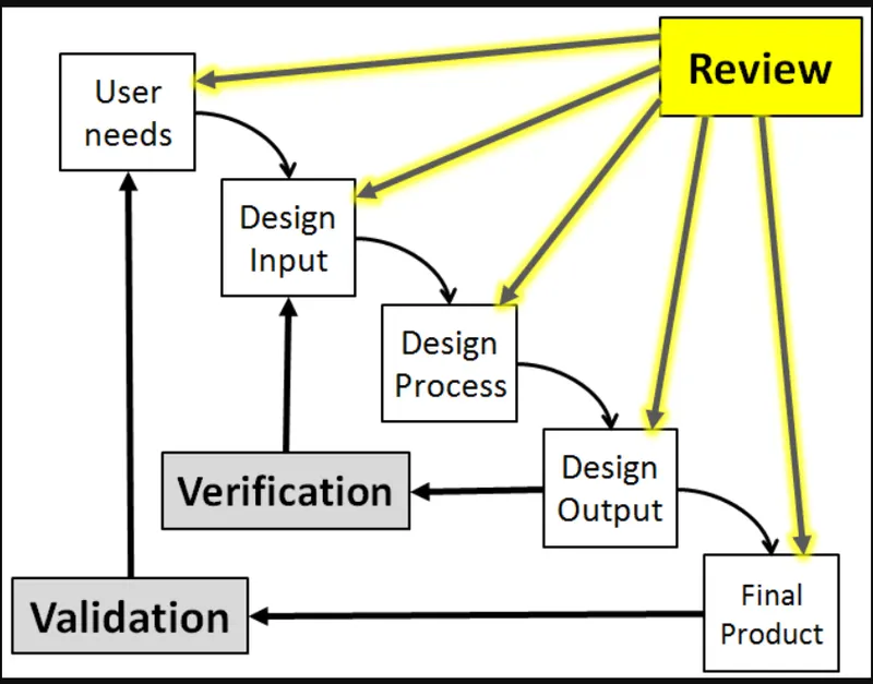
- A design output is a drawing or specification or manufacturing instruction. Design outputs describe all the components, parts, and pieces that go into your medical device. Design outputs describe all assemblies and subassemblies of your product.
- Design output documents must define the critical outputs (specifications, properties) and reference your acceptance criteria. All of this must be documented, reviewed, and approved before the design is released. The outputs also provide needed important information for purchasing, production, and servicing.
- The design of output is the most important task of any system. During output design, developers identify the type of outputs needed, and consider the necessary output controls and prototype report layouts.
- Choosing the right output method.
- Designing Output to Serve the Intended Purpose. All output should have a purpose.
- Designing Output to Fit the User.
- Delivering the Appropriate Quantity of Output.
- Making Sure the Output Is Where It Is Needed.
- Providing the Output on Time.
- Choosing the Right Output Method.
- At the end of this phase, a logical solution is defined which is passed to the Development phase. Prototypes are also developed in this stage. Another output of the Design phase is a road map which talks about the scalability of the solution at a later stage.
Q-10 What do you understand by structuring a design tree ? How does it reduce error during the design process ?
- Structuring a design tree implies to a process where all the assemblies & parts are named in a specific standard. Different customers have their different set of standards to structure a design tree.
- It is an important process which helps us to find a specific part or assembly as to which project , tool or unit , it belongs to.
- This helps us to avoid errors during design study , manufacturing , assembly , inspection etc.
- If the parts or assemblies are not properly or the design tree is not structured properly , it will create confusion to understand the design & may create a major possibility of creating errors.
- Naming of a fixture or a unit or a part gives the information as to which project or zone or assembly do they belong.
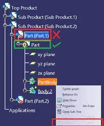
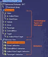
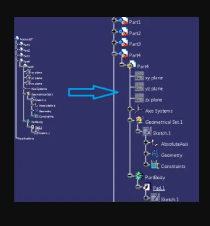
- Above images are just to refer that how we can maintain the structure tree.
Q-11 What are units ? mention 5 types of units.
- In general , units is a device that has a specified function, especially one forming part of a complex mechanism. A welding fixtures is a assembly of different types of units.
- The BIW fixture is assembly of different units which are designed to fullfill different purpose.
- The unit have specified function like resting the panel , clamping the part , locating the part etc.
- According to the 3-2-1 principle of fixture design the units are designed to locate & clamp the car panel to its specified position in fixture while operation is going on.
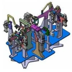
Types of units in BIW fixtures :
- Rest unit.
- Fixed pin units.
- Retract pin units.
- Rough locator unit.
- Sensor unit.
- Base unit.
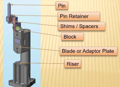
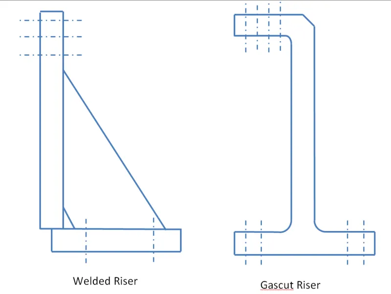
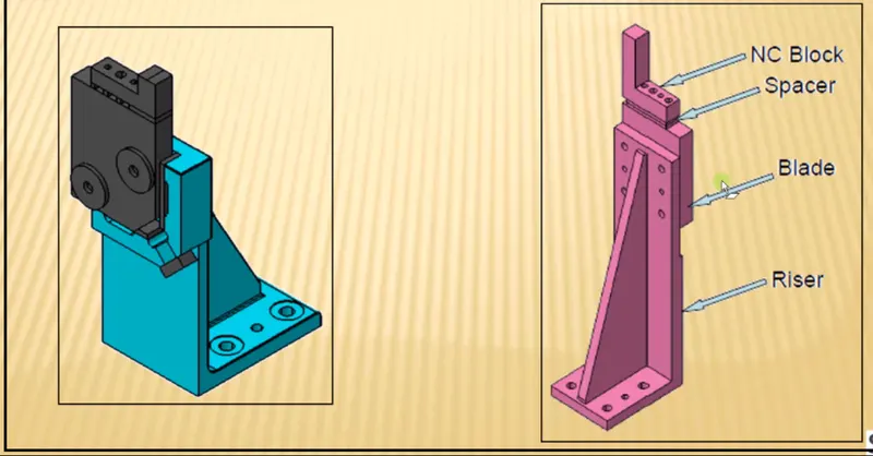
It is not necessary to have one riser where all the parts of clamp or rest or location units are mounted.
Generally risers are either made of plate fabrication or plate and tube welding together or from single gas cut plate.
- Mostly the design of riser depends upon the company guidelines.
A ) Gas Cut Risers: Many European companies use gas cut risers made by gas cutting up to 50mm or 63mm thick steel plate.
Advantage: No welding, Faster manufacturing, Standardization possible, cheaper than welding in some cases. Possible to have difficult profiles.
e.g. BMW. TATA Motors (India J riser)
BMW also use cast riser.
B ) Casting Risers:
Major BIW line builder Comau (Italy) has their own cast risers
Advantage: No welding, Faster manufacturing, Standardization possible, Shim adjustment in 3 direction possible in Comau case with dolly plate.
C) Welded Riser
In most of Asian companies from Japan and Korea it is common to use welded risers.
e.g. Wooshin
Important things which you need to keep in mind while designing riser
1) It should be firmly mounted on base plate. Should have enough no of bolts with proper grade for fixations and dowel for position location.
2) Height should not be too small or too high. Maintain the height to resting width ratio.
3) Ensure that riser mounted considering surrounding space around other units.
Ensure that there is enough space for spanner to unscrew riser.
4) It is recommended to avoid decimal coordinate of riser mounting on base plate.
5) Select proper bolt and dowel sizes for mountings of riser on base plate.
6) Select colour or powder coating as per the company requirement. Do not forgot to apply red oxide before paintings.
7) Do not paint machined faces? Take proper care while paintings.
8) Ensure proper dowel tolerances on the riser. (refer the Tolerances for Risers and Mylars in the “Tolerance for Riser and Mylar” blog topic )
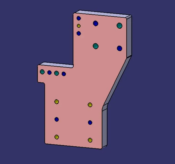
- But in the case of pins, this case is a bit different. If the pin is on the angle with respect to the carline and that angle is more is not more than 15 deg then the pin will have 2-way directional shimming, if Pin’s angle is more than 15 deg in any direction then 3 shimming will be used.
- Usually two locating pins are enough to properly locate the work piece on one plane.
- There are dozens of styles of locating pins that can be utilized in a design. We will explain the structure and show an example of how each style can be applied.
- One of the most common pins is a stepped pin with either small or large head.
Diamond Shaped Pin
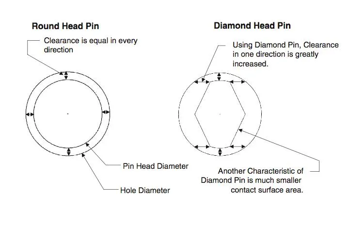
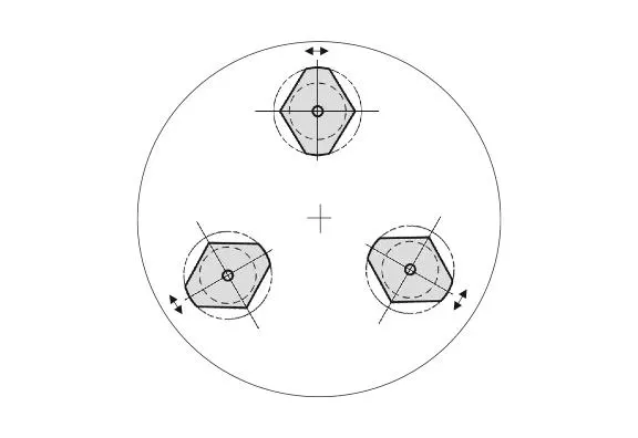
The Diamond Shape is a critical feature that helps with machining inaccuracies and smoother locating operation. When two round head pins are installed onto one plate, the distance between two mounting holes must be extremely precise and even then, the work piece will not be placed on the base as easily as it would with the use of a diamond shape pin.
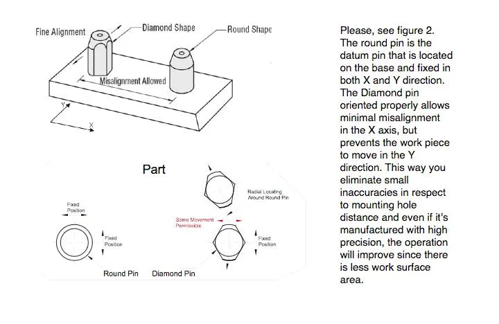
There are other ways of utilizing diamond locating pins. This is one example, where you need to perfectly align the center of the part, but the angular orientation is not critical.
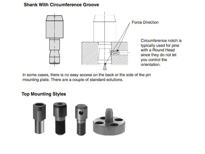
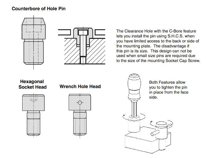
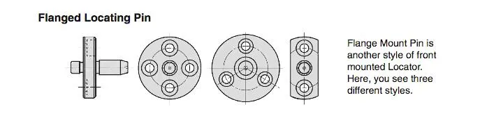
Shank mounting styles
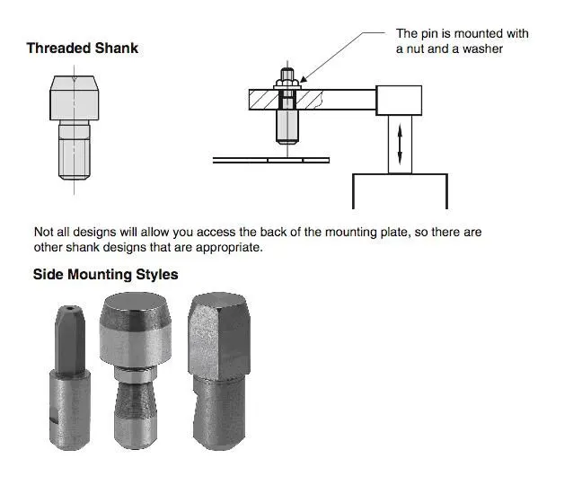
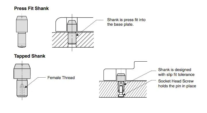
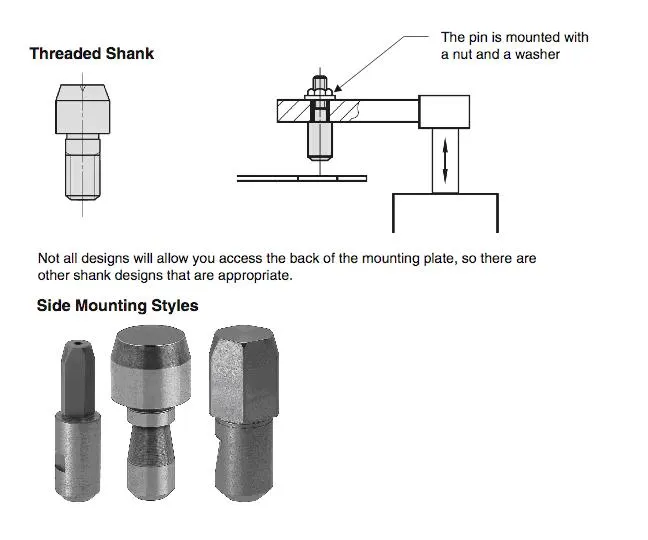
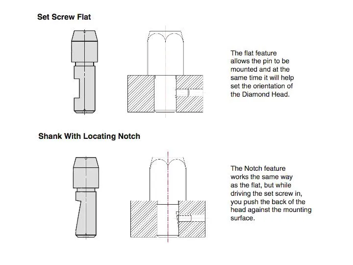
One of the locating pin features is a shank--the part of the pin that is installed in the mounting fixture and does not come in contact with the work piece. There are several different shank mounting configurations.
The press fit shank is used, when you have access to the bottom of the mounting plate. This way it can be knocked out when replacement is needed.
Different Pin Head Shapes
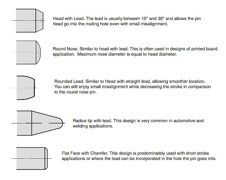
There are several styles of Pin Head shapes. They serve different purposes and can be utilized in a variety of applications.
Height Adjustment Pins
Height adjustment Pins use the face of the pin for crating spacing between the product and the pin’s mounting surface. The face of the pin usually needs to be hardened.
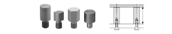
Locating Pins with Shoulder
Flanged pins are very popular due to their dual functionality. They provide both XY plane as well as Z height location.
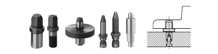
Stepped Head Pins (Also known as Double Pilot Pins)
Stepped Head design allows you to position two layers of work pieces as once. Often used when working with multiple pieces of sheet metal.
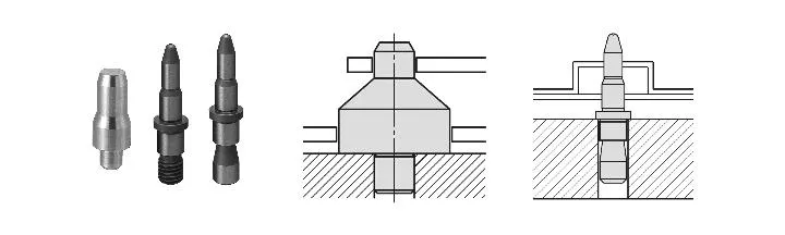
Head with Air Vent
It is beneficial to add an air vent, often in the form of a flat running along the side of pin’s head in order to avoid air compression inside the hole, especially when dealing with blind positioning holes.
Additional useful features
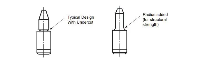
Most of locating pins are machined with an undercut feature that allows for the work piece to rest on the base. Sometimes more structural strength is required and you can design the pin with a radius if the positioning hole can be produced with appropriate chamfer.
A flat feature on the flange can also be used for orientation of the diamond pin. Please see the example below.
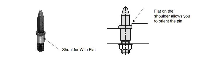
Materials
Typically, locating pins are manufactured from hardened tool steel such as O1 heat treated to 60-63Rc or from case hardened carbon steel (1045 with 45-50Rc). In some cases, soft 300 series or hardened 400 stainless is used in assemblies where no rust is accepted. Please, remember that pins made out of soft materials will wear out much faster than harden pins.
There is a variety of coatings that can be chosen based on your application. In corrosive environments, a hard chrome, Dicoat or TiCN coatings can help extend the life of the pin since they provide non-corrosive and hard layer that can be as hard as 3000 Vickers.
A variety of insulating coatings or materials can be used in case of welding applications. KCF stainless steel coat is one surface treatment that provides great insulation and prevents weld build-up between the work piece and the surface of the pin.
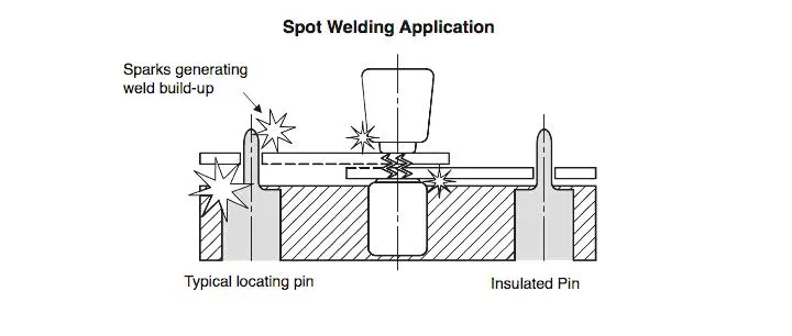
As I explained, there are many different features that can be combined in a design of your locating pin. The photograph below represents only some of the combinations of features introduced in this article. Possibilities are virtually endless. To view a complete line of locating pins please consult the MISUMI 2009 metric and inch factory automation catalogs available for order at "MISUMI USA"
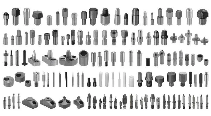
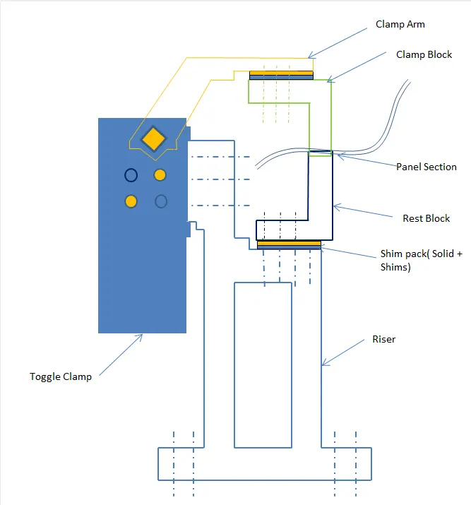
- But in the case of pins, this case is a bit different. If the pin is on the angle with respect to the carline and that angle is more is not more than 15 deg then the pin will have 2-way directional shimming, if Pin’s angle is more than 15 deg in any direction then 3 shimming will be used.
4. Pin retainer : It will support the pin.
- Usually two locating pins are enough to properly locate the work piece on one plane.
- There are dozens of styles of locating pins that can be utilized in a design. We will explain the structure and show an example of how each style can be applied.
- One of the most common pins is a stepped pin with either small or large head.
Q-15 What are the fundamental to design a sensor unit.
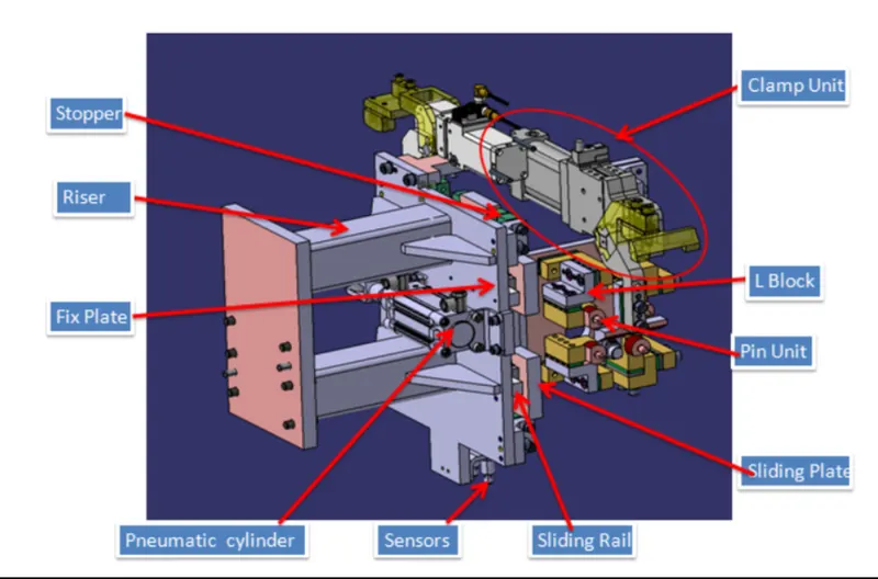
Adding Sensors To Weld Fixtures.
The conversation about whether to put sensors in weld fixtures is one we are having more frequently as manufacturers continue to invest in automating weld processes. There are several types and options when it comes to sensing. But before getting into details, the first question to be asked is “what problems are you trying to solve?” Adding sensors can help control quality and manufacturing issues, but it can also add unnecessary complexity and maintenance costs. Before assuming it is the magic bullet for solving quality and manufacturing issues, make sure you are aware of the downsides of adding sensors to your tooling as well.
Below we’ll outline some applications and options for incorporating sensors, along with some of the pros and cons with sensing in weld tooling. However, please note that incorporating sensors into weld fixtures has countless nuances and variables that can’t be covered in a blog article. This is just a basic overview to explain some of your options. If you would like to learn more about leveraging sensors for your next fixture project, we encourage you to reach out to one of our project managers to review your specific application.
Weld Fixtures and Proximity Sensors 101
Proximity sensors are one of the most common ways to incorporate sensing into weld fixtures. These sensors can be used in a variety of applications including part presence, poka-yoke, or even position verification.
Proximity sensors are categorized two ways – normally open or normally closed. Another way to think about this is the sensor verifying something is either present or not present. Both applications are used in weld fixtures. Other proximity sensors including capacitive proximity sensors, photoelectric sensors, and inductive proximity sensors. The materials and applications determine the type of sensor required. Proximity sensors also have a variety of field or beam specifications.
Typically, sensors are tied into an I/O (input/output) block or stand-alone PLC (Programmable Logic Controller) on the fixture. If they are tied into an I/O block, you can connect the sensors on the fixture to your robot. This allows robot programming to incorporate logic into the weld sequence like, “don’t start welding if all the parts are not present” or “make sure this hole is in the right spot before welding” or “open this clamp once this weld is complete”.
If the sensors are tied into a PLC on the fixture there is usually an HMI (Human-Machine Interface) as well. You can simplify the logic by just having red light/green light indicators, but if you are investing in sensing it usually makes sense to have an HMI as well. An HMI will give you a wide range of control and numerous options for using the proximity sensors. We are not getting into that level of detail in this article, but if you would like to discuss the options and details our team would be happy to assist you.
Part Presence Sensors
Incorporating proximity sensors for part presence is one of the most common applications when adding sensors to your weld fixture. The sensor will sense whether a part present or not – pretty simple (in theory). The obvious benefit of part presence sensors is you can verify all the component parts are loaded before either clamping or starting the weld sequence. This keeps you from welding your fixture if something is missing, which is a good thing.
You don’t necessarily need to sense every component part in the fixture in every application. Sometimes there is only one or maybe just a few critical component parts that require part presence sensing. Complex and/or high cost weldments are typically good candidates for part presence sensors.
One major downside to adding part presence sensors to your weld fixture is restriction of weld access. Not only do you need space for the proximity sensors, but the components to hold the sensors, as well as weld and spatter protection for both the sensor and the cables. This adds potential maintenance issues and costs.
Poka-Yoke
Poka-yoke is another common application for proximity sensors. The term comes from the Japanese phrase for helping a machine operator avoid mistakes (poka yokeru). Poka-yoke applications can verify the addition of left hand vs. right hand parts or indicate if a part is loaded backwards. Adding proximity sensors for poka-yoke applications can help reduce operator errors and decrease scrap rates.
Verifying secondary processes on incoming component parts, like checking for holes and location, is another common application. These applications keep the welder or robot from welding components with missing holes or secondary processes like forming, punching, etc. Of course, it’s better to check these component parts at the source, which will be another article. But whenever you catch them, it’s better to notice these types of mistakes before adding weld cost, having to grind welds off, or scrapping the parts all together. Anyone who has ever has to grind welds knows that should be avoided at all costs!
Position Verification
Position verification is another application for sensors. This is especially common when using multiple sub-assemblies and changeovers to accommodate similar but slightly different weldments using the same base fixture.
Options range from using proximity sensors to verify the correct sub-assembly is mounted to the base fixture in the correct spot to calling up the corresponding weld program according the relative sub-assembly. This can also be a great tool for verifying multiple length parts in an assembly or accommodating multiple lengths by using a linear rail. Sensors can verify the position of the linear rail quickly and reliably.
Of course, this can add complexity and cost to the fixture, so the cost benefits have to be weighed in each application.
Clamp Open/Closed
Verifying clamp open, clamp closed, or both is also a very common sensing application. Again, these are usually tied into either an I/O block or PLC on the fixture.
This application is very common in robotic weld tooling. Verifying clamps are closed helps prevent the robot(s) from crashing into open clamps. Creating weld programs that avoid both open and closed clamps is an obvious work around, but this can add complexities and programming time, not to mention inefficient robot paths.
Another application for clamp closed sensing is when you are rotating the fixture upside down (usually for weld access on the backside). Having sensors for clamp closed adds a level of safety and prevents the operator or robot from rotating the fixture and having parts fall out. This can be a major safety concern, especially when dealing with heavy parts.
Clamp open sensing has many applications and benefits as well. Verifying clamp open is tremendously beneficial when incorporating part ejection, as you can imagine. Hard to eject a part when it is still clamped! It is also crucial when integrating any sort of automated part tending or load/unload automation.
Pros and Cons
While there can be a lot of benefits to using sensors in your weld fixtures, there are also added costs, the possibility of increased maintenance requirements, and other potential issues that can compound in the process. If you can clearly ask “What problems am I trying to solve?” and state a solution that incorporated sensors can solve, then yes, it’s a good idea to look at the options. However, in our experience, if you cannot definitively say WHY you need sensors, adding them can cause just as many – if not more – problems than it solves.
There are also other options for verifying and controlling processes that are more mechanical in nature, for instance, incorporating logic into your pneumatic or hydraulic systems. We do this routinely for many applications. Logic can verify parts are located and/or seated correctly, check to make sure a hole is present for a poka-yoke application, or ensure clamps are open before parts are ejected pneumatically. Stay tuned for a more in-depth discussion of this in a future blog post!
Again, incorporating sensors into weld fixtures has countless nuances and variables that can’t all be covered here. This is just a basic overview to know some of your options. If you would like to learn more about leveraging sensors for your next fixture project, I would highly encourage you to reach out to one of our project managers to review your specific application. We would be happy to help any way we can.
Q-16 What is rough locator unit ? What are the fundamental to consider while designing it.
- Rough locators helps to locate workpieces in the automation process. Locating refers to the desired location where you want the workpiece to be when it is getting worked on either by a person, team, or robot.It is a device to establish and maintain position of a part in a jig or fixture.
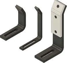
The basic fundamental to consider while designing :
- Rough locators should be placed at edges of the car panel which has to guide.
- Rough locators should be placed at the same angle of the car panel edge with min. distance of 2-5 mm from the edge of the car panel.
- Rough locators should guide the panels in pin assembly direction in general.
- The slot should be in direction of car part only.
Q-17 What is a base unit ? Describe its parts.
- A base unit is the unit designed to mount all the other units(Clamp unit, Pin unit, rest unit etc.) of the tool, also other parts necessary for a tool like pneumatic valve box, trunking cable path will also be mounted on to a base unit.
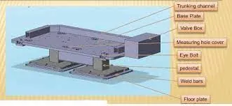
Parts of base unit :
1. Valve box
2. Truncking channel.
3. Measuring hole cover.
4. Eyebolt
5. Pedestal
6. Floor plates.
1. Valve box.
- A valve box is a box that supplies air to all the pneumatic cylinders assembled in the fixture valve box consists of one solenoid valve with one inlet & one outlet. The outlet in the solenoid is used to
supplies air to the pneumatic cylinders from the valve box whereas , the inlet in the solenoid valve is used to collect the air from pneumatic cylinders to the valve box.
2. Truncking channel.
- Tuncking channel is kind of cable duct. Which helps to guide & protect the wiring / tubes used in the fixture.
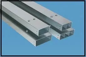
3. Measuring hole cover.
- In the measuring hole cover the co-ordinates points are engraved on it. The hole which mentions the co-ordinates gives the position & placements of the particular units.
- The measuring hole helps in CMM & OC inspection.
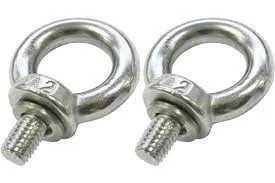
4. Eyebolt.
- The eyebolt is bolt with loop at one end , they are firmly attach a securing eye to structure so that ropes or cable may then be tied to it for lifting purpose.
- Eyebolt is used to drag or lift the base unit while relocating.
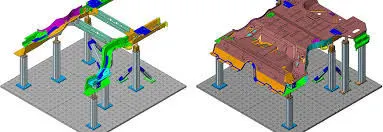
5. Pedestal : Pedestal is a stand like structure where the entire unit of the base will be mounted.
6. Floorplates.
- Floor plates are used to mount the entire base unit with floor.
- also it helps to achieve flatness for the future.
Q-18 What is dump unit & what are its function ?
- Dump unit is the complex unit to design due to space constains there is less space avilable & have to adjust all the parts in available space. It consist of dump cylinder to perform the operation of clamping & unclamping car panel.
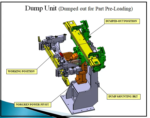
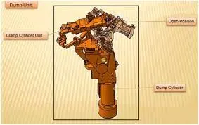
Function of dump unit :
- To ensure proper resting of the panel being welded and to restrict its motion. To ensure there are is no rotation in the panel and to fix it either by pins or side blocks or magnets.
Q-19 What is a slide unit ? mention were slides unit are commonly used.
- Slide units are positioning units , which are used to position of the car part or panel units weld gun , slots for further operations.
- Slide units may be classified into two types :
1. Handed guideway.
2. LM guideway.
- Slide units may be further classified into three types based on prime movers :
1. Manual slides
2. Hydraulic / pneumatic slides.
3. CNC slides
- It may also classified depending on applications :
1. Horizontal slide unit.
2. Vertical slide unit.
3. Angular slide unit.
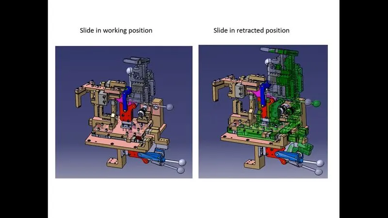
Fundamental of slide units design :
1. Reverse stroke of 10 mm to be consider in both forward & retracted conditions.
2. Cylinders & LM guides to be validated for load & stroke.
3. LM guide rail length to be standard & more than the actual stroke.
4. Master guideway should be constrained & the subsidiary guideway to be free.
5. Mechanical hard stop to be considered for both extented & retracted condition.