Week 3:- BiW Fixture Design Methodologies Challenges
1.What is Design Methodology?
Ans: Design methodology is the steps followed during the concept designing stage of fixture design.
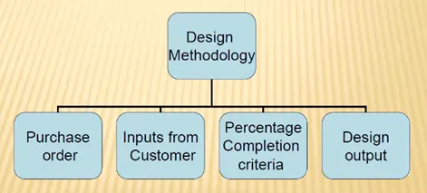
The steps in design methodology are:
1. Purchase order: The purchase order is the document received from the customer which gives the details of the product, time plan.
2. Inputs from customer: The customer gives the details of the fixture corresponding to the standards followed by the company.
3. Percentage completion criteria: It gives details about the project completion and the estimated time period to complete the project.
4. Design output: The 3D, 2D CAD files along with the GD&T have to be submitted to the customer. The documents such as BOM(Bill of materials) have to be submitted.
2. What are the inputs required from the customer to start designing a Fixture?
Ans: The inputs from the customer are:
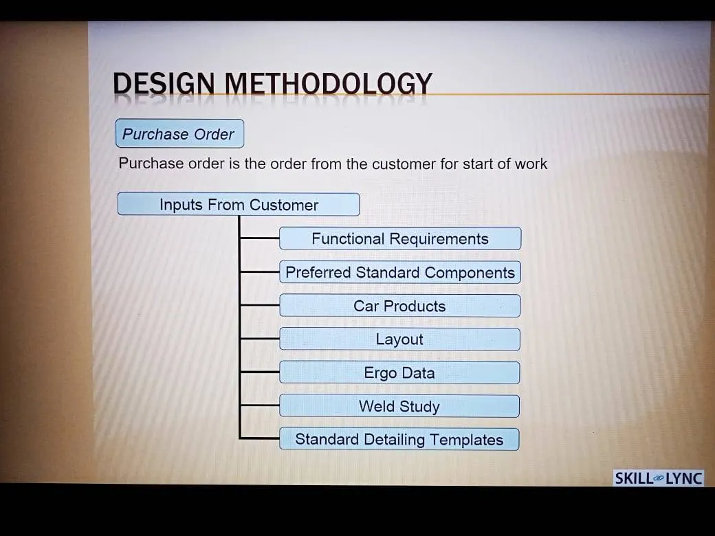
1. Functional requirements
2. Preferred Standard components
3. Car Products
4. Layout
5. Ergo Data
6. Weld Study
7. Standard Detailing Templates
1.Functional requirements: In this, the information about what kind of function the fixture is going to have such as welding, reverting, gluing, etc., will be given.
2. Preferred Standard components: The details of the standard parts that the company is using are given which saves a lot of time as the design is not required and the company no need to purchase from outside.
3. Car Products: The 3D and 2D files of the car design, what kind of car products the fixture has to be modeled. The study of GD&T and the PLP(Principle locating points of the car).
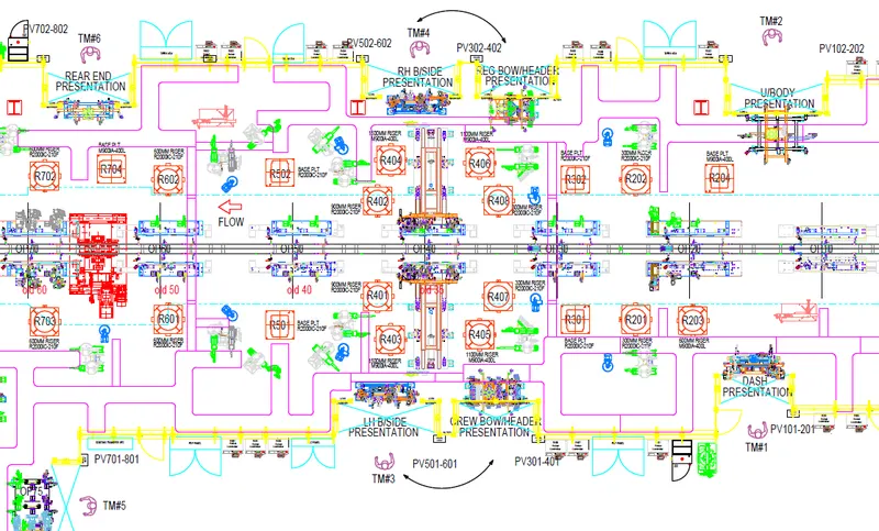
4. Layout: The layout of the assembly line. To understand the flow of the process, to constrain the part in that flow.
5. Ergo Data: This is the standard data that every company will have. If the data is given the fixtures are designed accordingly. This gives the data about how comfortable the operator operates the machine.
6. Weld study: This is an important study in fixture design. This gives the details of where the weld gun is located, what kind of weld gun (resistance spot welding, seam welding) is used. The entire fixture design depends on it.
7. Standard detailing templates: Every company is having a different standard template and need to get the data in the same format.
3.What is the input we get from "Car Products"?
Ans: The car product includes:
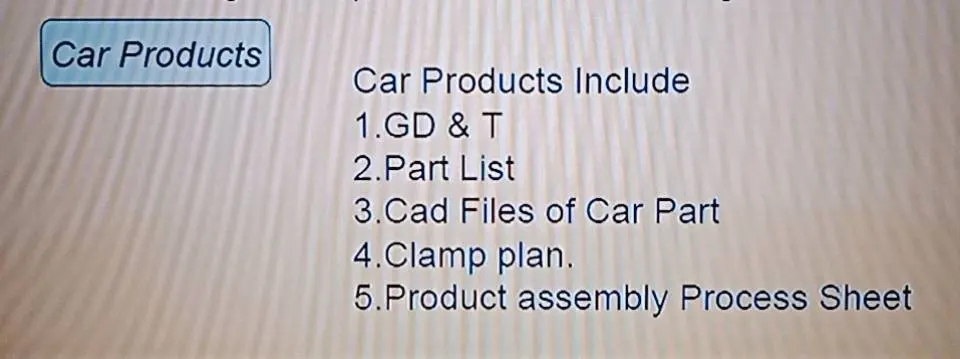
1. GD&T
2. Part list
3. CAD files of car part
4. Clamp plan
5. Product assembly process sheet
1. GD&T: This gives the geometric dimensioning and tolerances information which includes the datums, feature control frames. Locating pins, Rest, Clamp, Dumps and slides information of each station. The sequence of opening of clamps, dumps and slide stroke information.
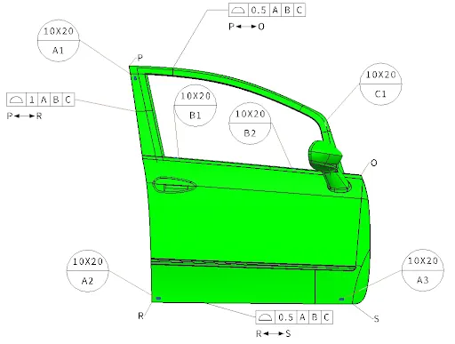
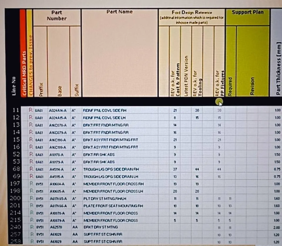
2. Part list: This gives information on what kind of assembly the part is going to be. For example, the assembly of the hood inner panel and outer panel, latch and striker assembly, so different assemblies will have different fixture units so the part files are made according to the fixture unit.
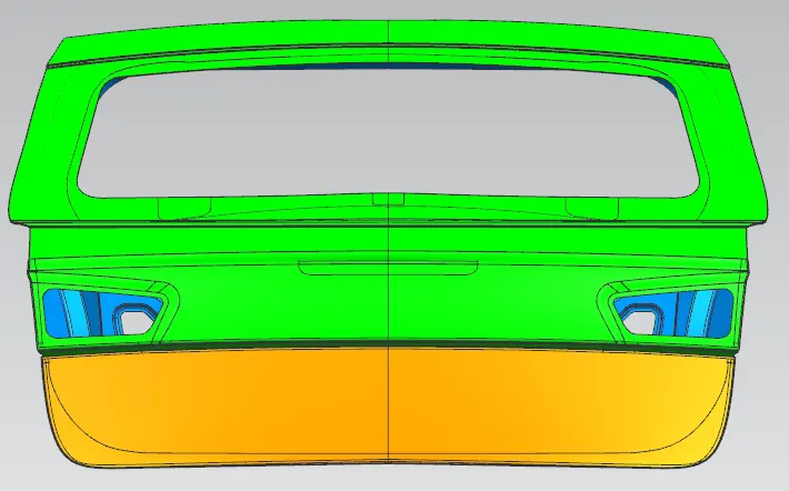
3. CAD files of car part: 3D and 2D CAD file of the car product.
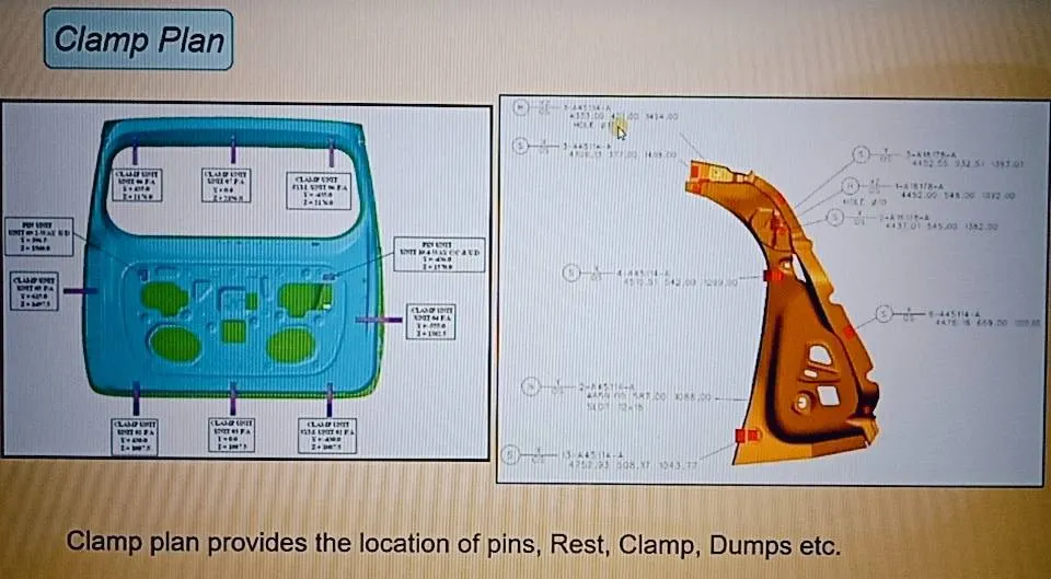
4. Clamp plan: It is a very important input from the car product. The position of clamping units or the particular pin unit placement details are given. The important point is never to change the position of the clamp given in this data, the design can be changed according to the clamp.
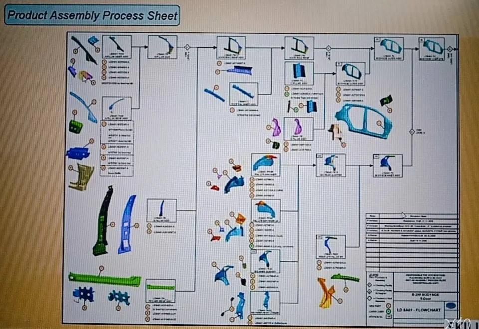
5. Product assembly process sheet: It gives the details of how the assembly of parts takes place. If there are any constraints need to contact the customer so they will change according to the requirements. This provides the information of the assembly line, cycle time.
4. What is the Clamp plan?
Ans: The clamp plan gives the details of the location of clamps, pins, and fixtures. This is very important information in the fixture design. With the data provided in the clamp plan, the fixture can be designed. The weld spot location is also provided in the clamp plan. If the weld spot is nearer to the clamping unit, need to consult the customer to give the difficulties in designing the fixtures.
The clamp plan provides an idea to the design team how the fixture has to be designed. Utmost care has to be taken so that there shouldn't be any dimension change of the pins or fixtures in the assembly line. A small change in the dimension changes the entire assembly of the part.
Fixture planning determines precise locating and rigid clamping of a workpiece according to workpiece design and process requirements. The locating planning chooses surfaces on the workpiece as locating planes and selects suitable fixture components for locating these surfaces. Locating surfaces are classified as plane, pin-hole and external profiles. Commonly used fixture locating methods include 1) 3-2-1 point locating for prismatic workpieces, it uses three locators on the primary locating surface, two locators on the secondary locating surface, and one locator on the tertiary locating plane; 2) one plane and two pins locating for general parts with two holes. It uses a primary locating plane, a primary pin, and a second pin to restrict the freedom of a workpiece; 3) V-block locating for external cylindrical parts. One wide V-block or two short V-pads may be used to hold the workpiece.
The clamp plan provides the location of pins, rest, clamp, dump, etc. It gives the exact location of the pins in the X, Y and Z coordinates.
5. What is the purpose of a Layout?
Ans: The main purpose of the layout is to know the space constraints and to design the fixtures accordingly.
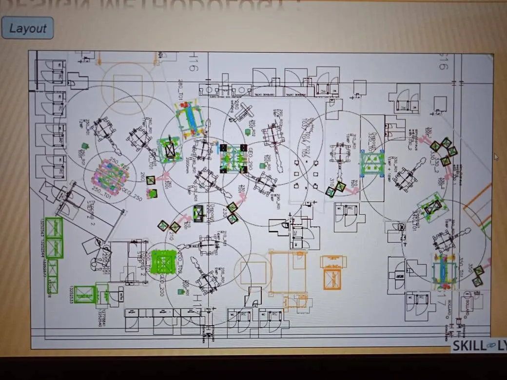
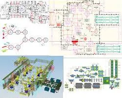
The above fig. gives the outlook of the layout in the industry where the fixtures and robots are placed according to their sections. The circles indicate the swept area of the robot, which is the area it can be covered. The name geo_250_T01, geo indicates the purpose of the tool here it is geo tool, 250 is the name of the section and T01 is the tool number one.
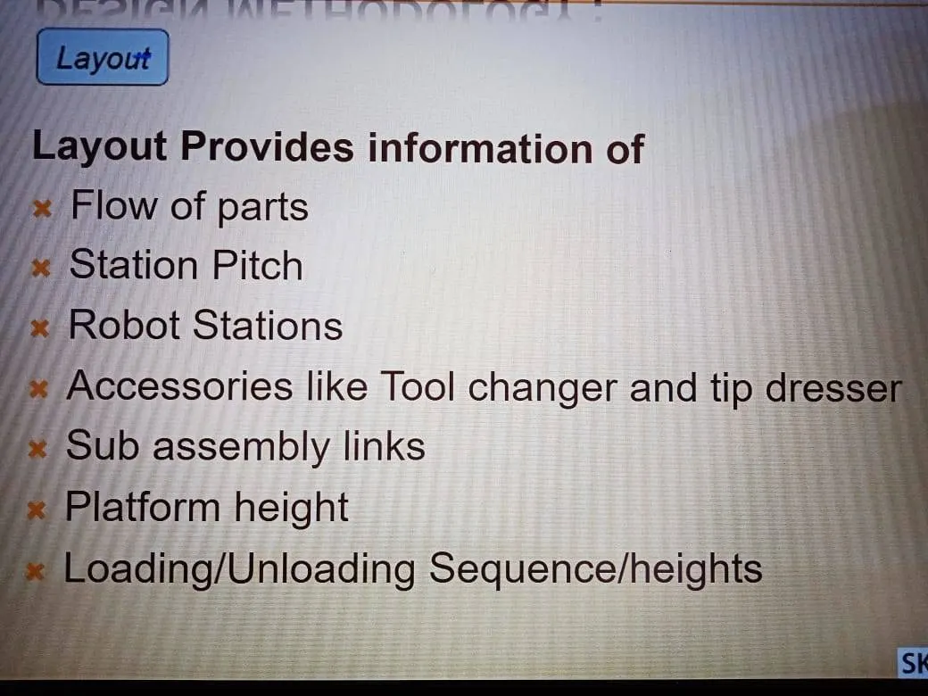
The layout provides the information of
1. Flow of parts: It informs about the movement of parts from one station to another station.
2. Station pitch: It gives the distance between two stations and the constraint of space between the two stations in the industry.
3. Robot station: The robot location and the swept area information is provided.
4. Accessories like Tool changer and tip dresser: If the robot wants to change the tool, it has to go to a particular tool station and come back to its location. Tip dressers are for weld gun which sharpens the tips.
5. Sub assembly lines: It gives information about how the assemblies are linked to the main assembly line.
6. Platform height
7. Loading\Unloading sequence\heights
6.What is Ergo data?
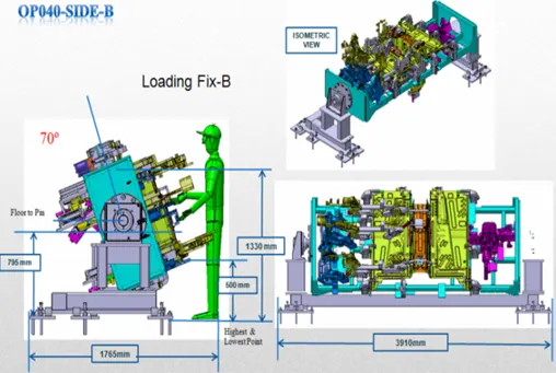
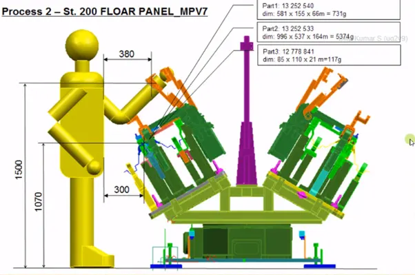
Ans: Ergo data refers to human behavior and movement. It provides information about loading height, working safety zone of the operator. The ergo data are standards and depend on the company.
The terms ‘ergonomics’ and ‘human factors’ can be used interchangeably, although ‘ergonomics’ is often used in relation to the physical aspects of the environment, such as workstations and control panels, while ‘human factors’ is often used in relation to the wider system in which people work. On this site, we generally use the term that fits most closely with the research or the industry that we are discussing.
Ergonomics is a science-based discipline that brings together knowledge from other subjects such as anatomy and physiology, psychology, engineering and statistics to ensure that designs complement the strengths and abilities of people and minimize the effects of their limitations. Rather than expecting people to adapt to a design that forces them to work in an uncomfortable, stressful or dangerous way, ergonomists and human factors specialists seek to understand how a product, workplace, or system can be designed to suit the people who need to use it.
In achieving this aim, we need to understand and design for the variability represented in the population, spanning such attributes as age, size, strength, cognitive ability, prior experience, cultural expectations and goals. Qualified ergonomists are the only recognized professionals to have competency in optimizing performance, safety and comfort.
7. What do you understand by Weld study?
Ans:
Welding is a fabrication process that joins materials, usually metals or thermoplastics, by using high heat to melt the parts together and allowing them to cool, causing fusion. Welding is distinct from lower temperature metal-joining techniques such as brazing and soldering, which do not melt the base metal.
In addition to melting the base metal, a filler material is typically added to the joint to form a pool of molten material (the weld pool) that cools to form a joint that, based on weld configuration (butt, full penetration, fillet, etc.), can be stronger than the base material (parent metal). Pressure may also be used in conjunction with heat or by itself to produce a weld. Welding also requires a form of shield to protect the filler metals or melted metals from being contaminated or oxidized.
Many different energy sources can be used for welding, including a gas flame (chemical), an electric arc (electrical), a laser, an electron beam, friction, and ultrasound. While often an industrial process, welding may be performed in many different environments, including in open air, under water, and in outer space. Welding is a hazardous undertaking and precautions are required to avoid burns, electric shock, vision damage, inhalation of poisonous gases and fumes, and exposure to intense ultraviolet radiation.
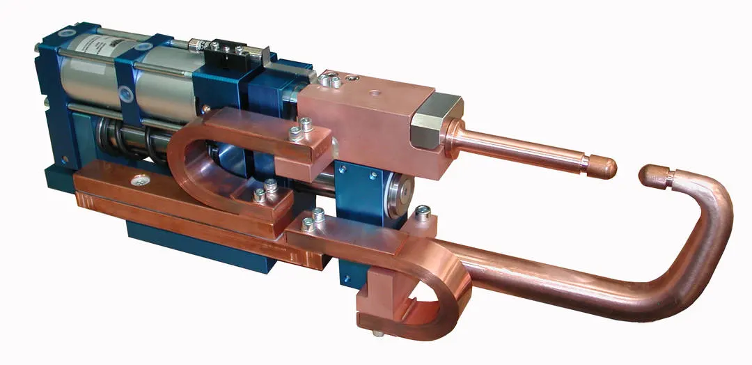
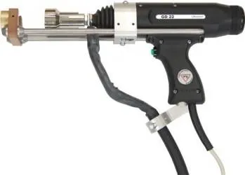
Weld gun a portable device for semiautomatic welding of parts of various articles. Guns are used where welding with stationary equipment would be difficult or impossible. They are used in the manufacture of automobiles, railroad cars, farm machinery, and similar equipment. They are also used for work performed under unusually complex operating conditions, such as exist on orbiting spacecraft.
There are welding guns for resistance spot welding, arc welding (including flux-cored and gas-shield arc welding), and electron-beam welding. The guns can also be used for welding various parts and components of machines, mechanisms, and structures, for example, rollers, hooks, and pins. There are many types of welding guns, the design being determined by the intended use. Thus welding guns for resistance spot welding consist of a frame on which the electrodes and a pneumatic cylinder for compressing the electrodes are mounted. Arc-welding guns are designed so that the discharge occurs between the stationary electrode and the workpiece; guns for flux-cored arc welding are equipped with a flux-cored electrode.
8. What are the criteria for percentage completion in the designing stage? Explain it in detail.
Ans: percentage completion is followed in designing stages and dispatch stages in the welding fixtures. It provides information about the workflow of the project. In which stage the project is currently. By this data, the project completion time can be provided to the customer. There are four different stages:
1. 0 - 25% - Input and concept design.
2. 25 - 40 % - COncept approval and simulation check
3. 40 - 85 % - Design freezing and detailing
4. 85 - 100% - Check and final dispatch
1. 0 - 25% - Input and concept design: The fixture study, designing of the CAD model occurs at this stage. If the design of the model is completed then the project will be 25% completed. If the design doesn't complete in the specified time limit but only a certain portion of the design is incomplete then the project completion will be less than 25%.
2. 25 - 40 % - COncept approval and simulation check: Once the CAD modeling is completed, the design is sent to the simulation team where they will check the design whether it is according to the details given by the customer or not. The assembly simulations are conducted. IF the design passes all the simulations then the project will be 40% complete.
3. 40 - 85 % - Design freezing and detailing: After the simulation, the design will be freezer and all the details will be checked.
4. 85 - 100% - Check and final dispatch: Once the detailing is completed the design will be sent to QC (Quality check) department. Once the QC department agrees then the fixture goes to the manufacturing unit.
The percentage criteria are updated at each stage to the customer and the exact deadline will be provided.
9. Brief about "Output" in design?
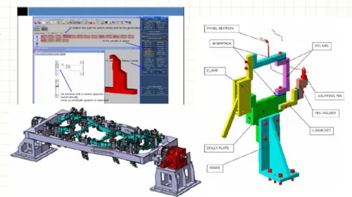
Ans: 1. The output is 3D models and 2D drawings of the design.
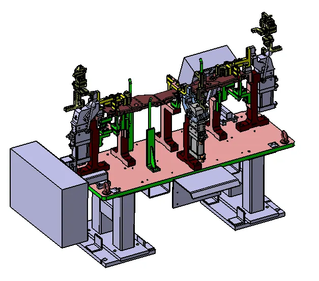
2. Unitized tools (multiple tools on the common base) require two types of drawing
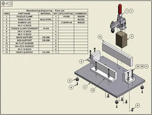
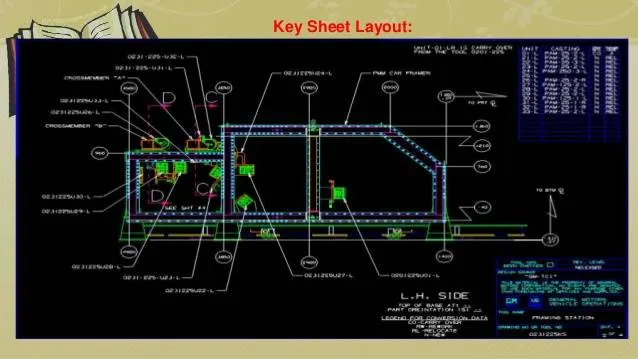
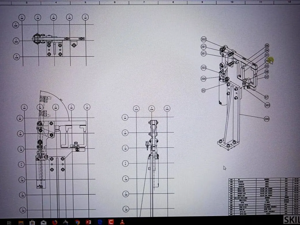
a) Key sheets: An index of units and their placement on the tool base. The orthogonal view of the fixture is shown. Each component is numbered and the list is provided at the bottom section of the sheet. If any assembly line changes it can be easily identified in the QC but this becomes the extra cost. It helps in the assembly whether every component is in its right place or not.
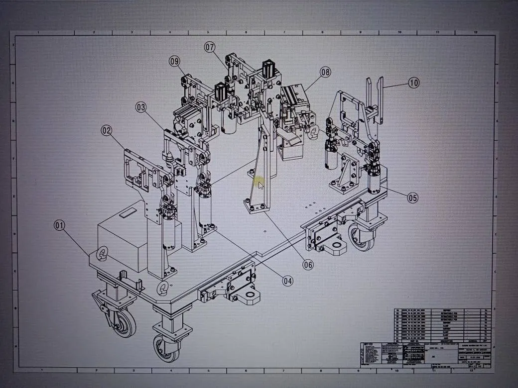
b) Layout sheets: A detailed drawing of individual units that include all of their components. The detailed information about the component is given and also their orientation.
3. Non-utilized tools: Tools that can stand alone and completely detailed in a layout sheet.
The output should compile the following point:
1. Approved standard components are to be used wherever possible.
2. Design must be as simple and economical as possible.
3. Design must comply with all current safety and ergonomic requirements.
4. Adequate error-proofing provision must be incorporated into each design by providing proximity switches, rough locators etc.,
5. The weight of the moving parts must be kept to a minimum while maintaining maximum strength.
6. Frames and structures are to be simple and sturdy.
7. Design clearance and accessibility for routine maintenance and service.
8. Motion control must be considered on any moving equipments.
9. Designer is responsible to validate clamps and all weld guns.
10. What do you understand by structuring a design tree? How does it reduce errors during the design process?
Ans:
SPECIFICATION TREE STRUCTURING: –
SUGGESTIONS
- The SPECIFICATION TREE is the place where the histories of the features modeled are captured. So it is highly important to have an organized tree structure that gives ease for navigation of the features when any modification takes place.
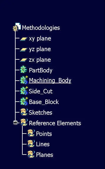
- shows the SPECIFICATION TREE in a structured manner. The Machining Body features are grouped under one body and base block features in another and so on with appropriate feature operations.
- It is also important in structuring the reference and construction element in the tree in an orderly manner, like the one shown in the figure right.
- The points that would be often used (like the Global Origin Point 0, 0, 0,) can be created under Points GEOMETRICAL SET and any reference planes defining legal limits can be created in the planes GEOMETRICAL SET.
ADVANTAGES OF HAVING STRUCTURED TREE
Transparent design intent achieved Navigation of features becomes easy.
Modification of features becomes easy.
BEST PRACTICES
- No usage of hybrid modeling in the parts. (Client Dependent Requirement)
- RENAMING APPROPRIATE FEATURES & BODIES IN SPECIFICATION TREE: –
SUGGESTIONS
- The renaming of features within the design becomes mandatory as it will be useful for the end users to by far identify things for modification.
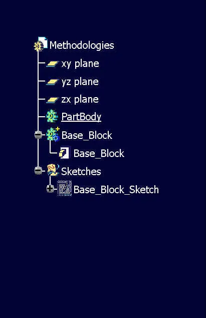
- For instance an end user who wants to identify the M5 holes on the model the SPECIFICATION TREE helps easily in identifying the M5 holes in the model thereby making modifications easy.
- Also renaming all the features every now and then as it is created will easy things at the end.
- Figure shows the features pad and sketch renamed as “Base_Block_Sketch” and “Base_Block” which will be useful in identifying them at a later stage.
- Renaming the Bodies also helps in navigation.
-
ADVANTAGES OF RENAMING
- Easy identification of Features & Bodies in SPECIFICATION TREE.
- Using Search Command Effectively to find features.
- Modification of features becomes easy.
BEST PRACTICE
Rename the features relevant to operations performed in a logical manner.
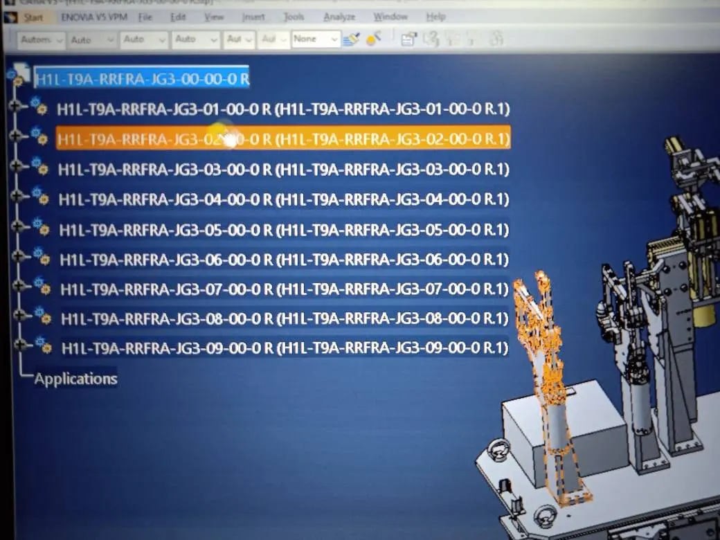
11. What are Units? Mention 5 types of units.
Ans: The location and orientation of other critical units of the fixture including clamps, locators, etc. They are decided based on the weld spot distribution. The weld spots for panel-side bracket assembly are located with respect to the body line of the car. These weld points give in form of coordinate (X, Y, Z). A unit is a device that has a specified function, especially one forming part of a complex mechanism. The BIW fixtures are the assembly of different units that are designed to fulfill a different purpose. The unit has the specified function like resting the panel, clamping the part, Locating the part, etc.
1) Fixed pin unit- It is fixed to the base and it cannot be moved.
2) Retract pin unit- It is a locating unit that can be moved.
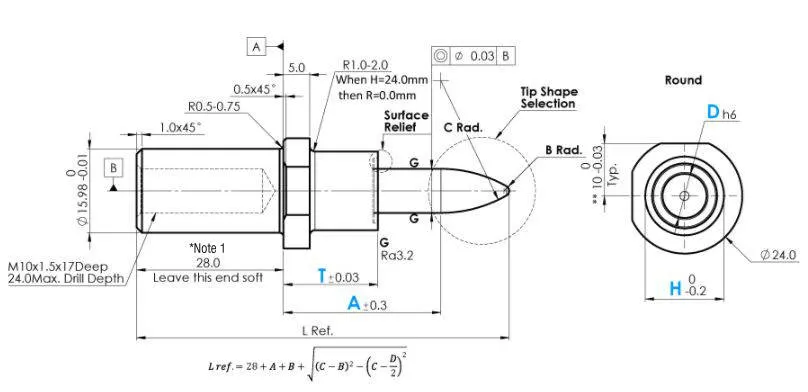
3) Rough locator unit- It roughly guides the operator for locating the part.
4) Rest unit- The panel is rest on this unit.
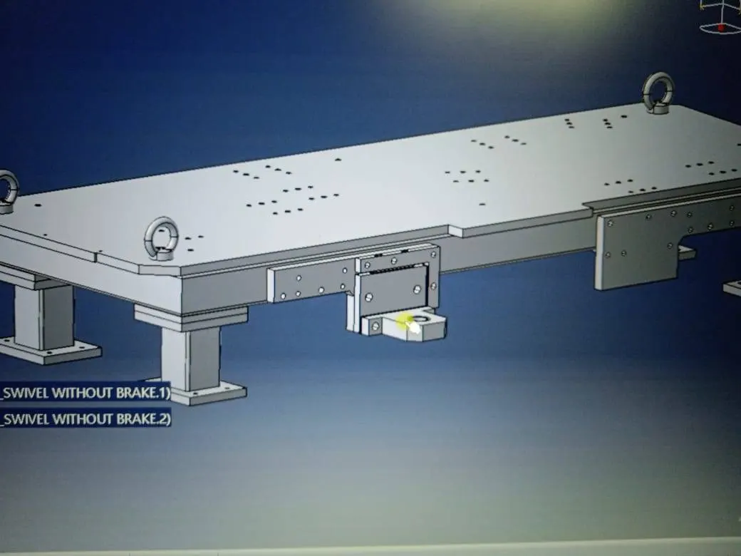
5) Base unit- It is the unit on which all other units are mounted.
12. Describe Fixed Pin units & their purpose?
13. What are the different parts of a fixed unit?
Ans for 12 & 13). Fixture pin unit hold the car part firmly and prevent the part from distortion while carrying out the spot welding
operation.
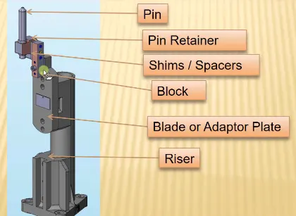
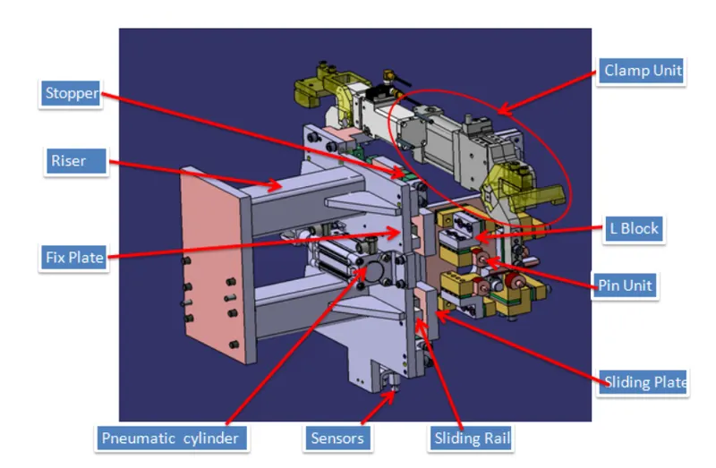
A single clamping unit consists of the following parts:
1. Finger: The finger is a movable part that is used to hold the Car part from the top against the Back-up and they are usually mounted on the clamp arm.
2. L-Block: L - Shaped blocks (single or in combination) used to mount the finger to clamp arm, besides allowing adjustment for locator pin in two directions.
3. Shim and spacer: They allow the finger to be moved to the correct XYZ locating and/or allow the customer to make adjustments to improve the quality of their product.
4. Blade: Part onto which the aforesaid elements are attached to.
5. Blade spacer: It allows the finger to be moved to the correct location in one direction.
6. Riser: L- shaped tall block with regularly patterned holes to attach the above-mentioned parts in a modular way Blade space.
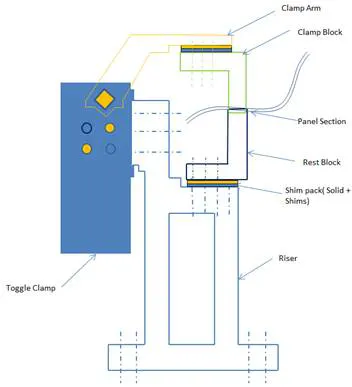
Study the PLP (Principle Location Points) data along with the nearby spot data. Depending on the angle of the cross-section. Mylars will be having shimming either in one direction or in 2 directions. General Thumb rule if the section is inclined more than 15deg or clamping surface is 3D profile then 2 directions shimming are provided. Take an overview of the working height if you’re having manual welding. For robotic welding also it’s important to see the working height in consideration of the robotic gun, turntable height if manual loading is done. Put the proper gun at the spot location. If process engineer has a gun shape stick to X, C or Y type of gun. Do the proper gun study and place the gun as per the GEO or re-spot decision and operator approach. Once the basic gun is placed considering the throat depth and throat gap start building the clamp and rest block at the PLP.
14. What is the purpose of making a Rest unit & describe its parts?
Ans:
These units are used to rest the panel. Take an overview of the working height if you’re having manual welding. For robotic welding also it’s important to see the working height in consideration of the robotic gun, turntable height if manual loading is done. Put the proper gun at the spot location for all the spots near the rest unit. If process engineer has gun shape stick to X, C or Y type of gun. Do the proper gun study and place the gun as per the GEO or re-spot decision and operator approach. Once basic gun is placed considering the throat depth and throat gap start building the clamp and rest block at the PLP.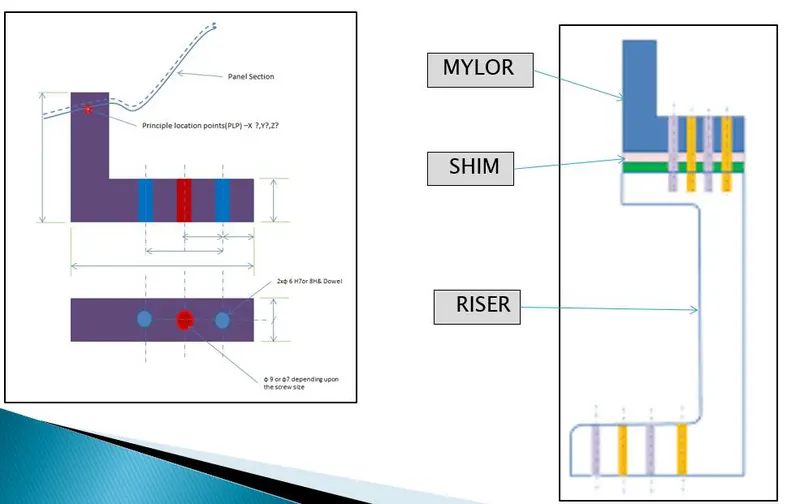
Panel section creation: Take a section at PLP either in clamp opening direction or normal direction. Sections should be normal to base. Panel section through X, Y or Z direction passing through PLP. The section will help in finalizing the shape of the clamp and rest block. Most importantly used for the finalization of gun shape. Finalization of a base plate plane – consider the following things before deciding the base plate. Height of maximum and minimum weld spot from the floor. No gun arm should touch the base plate. Operator ergonomic while accessing all the spots.
Construction of Rest Block: If standard Mylar has to be used (Few companies make standard height and length of steel blank with few holes and dowels for clamping) then select the proper blank size as per the requirement; consider 5 mm above the panel. As per your company or OEM, Tier 1 standard uses the different standards mounting risers. Do not forget to add the 5mm shim. If you are combining rough locator or part sensor bracket along with the rest unit. Take necessary care means a distance of rough locator from the panel. In the process of manufacturing, we use Steel Aluminum, S-grun, and Plastics. And hardening is necessary in manufacturing Mylar and Pin.
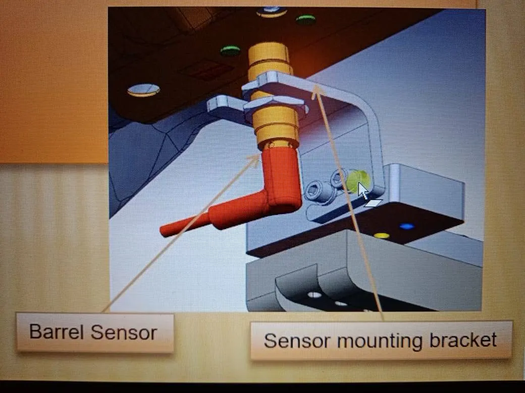
15. What are the basic fundamentals to design a Sensor unit?
Ans: There is a probability for incorrect loading of a workpiece in the fixture due to the ambiguity in the fixture design . Fixture foolproofing is a prevention or detection of such errors before additional value is added to the parts and make the fixturing process unambiguous. The incorrect loading of a workpiece in the fixture can have disastrous consequences or rejection of the manufactured part.
With a lot of progress in the sensing technologies in the recent years, one of the possibilities explored here is to place sensors in the fixture to verify the proper location of the workpiece. Various sensors were studied and one of the main limitations were the space available to install those sensors. As the locators were tiny (Diameter around 0.125 inches), we narrowed our search to a group of sensors that could be installed inside the ceramic locators. One of the most promising sensors we found was the fiber optic sensors. Another reason we liked these sensors is the ability of these sensors to operate in a rugged environment, with an IP-67 class rating these sensors had the ability to work under those conditions, especially in the EDM environment. Various designs were made based on sensors and applications. The sensors would be placed inside the locators away from the contact locations at different places in the fixture to verify the proper location.
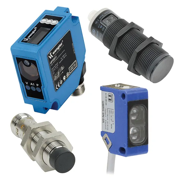
A sensor unit is a designed to sense the car panel by using Electrical sensors. The signal from the sensors will be fed to the PLC and so the next process will be executed by this signal.
Fundamentals of Sensor Unit design:
1. Every single loose panel which are being welded in a tool should be sensed.
2. Each panel should be sensed by 1 to 2 sensors depend on the size of panel, Preferred to be in diagonal opposite ends of panel.
3. Every sensor should be mounted in a 3 direction adjustable way in general.
Type of the sensors used in general:
1. Proximity sensor
2.LASER sensors
3. Photo electric sensors
16. What is a Rough locator unit & what are the basic fundamentals to consider while designing it?
Ans: Rough locators are elements that aid the operator to guide the car panels while loading onto the fixture and ensure a fool-proof assembly. the locating pins are used to loc' a body part in a position sufficiently accurate to execute a welding process. The body part is constrained by a set of appropriately locating pin so total constraint by locating pin should be fully constrained at all times to prevent any movement. (Usually two locating pins are enough to properly locate the body part on one plane. one of the pins is round, and another one is diamond shaped. This configuration will allow easier loading of body part. The end of each pin has a round or conical shape or is chamfered for the purpose of maintaining work ability such as ease of loading prevention of damage. The taper lead angle is large, 60 degrees or less, for small-size body parts and manual operation. The difference between the locate hole in the panel or body part and the locating pin diameter should be -.05 mm and a tolerance for locating pin should be 0, +.05mm. The dimension from the panel to the locating pin leading end 2straight area3 should be 1 mm. pins are available in numerous shapes and sizes in a design. There are two configurations for position of locating pin: i) keep two dowel pins for positioning as far apart from each other as possible ii) Set the dowel pins in symmetrical positions . One of the principal purposes of a locating surface is to locate and support the panel surfaces for performing a welding process. This is usually done with the datum surfaces that are reference for locating surface. The dimensions of datum surface are decided by selecting a necessary cross-section from the part drawing. The shape of locating surface is a form of cross-section of panel. Locating surface is configured to receive panel for setting in a correct position and locating a body part from any surface such as flat, curved, or have an irregular contour. In most applications, locating surface devices locate a panel by its external flat surfaces and flat area, such as% edges, flanges, steps, faces, shoulders, and slots.
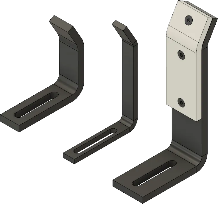
Fundamentals of Rough locator design:
- Rough locators should be placed at the edges of the car panel, which it has to guide.
- Rough locators has to be placed in the same angle of the car part edge with a minimum distance of 2-5 mm from the edge of the car part.
- Rough locators should guide the panel in pin arresting direction.
- Rough locator should start guiding the panel before 10 to 15 mm to the start of the pin engagement.
- Rough Locators should be designed with entry angle for car part entry.
- Rough locators should be designed with two slots to mount for easy adjustments.
- The slots should be in the direction of car part guiding.
17. What is a Base unit and describe it's parts?
Ans:
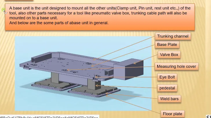
A base unit is a unit designed to mount all the other units (Clamp unit, pin unit, rest unit) of the tool, also other parts necessary for a tool like pneumatic valve box, trunking cable path will also be mounted on to a base unit.
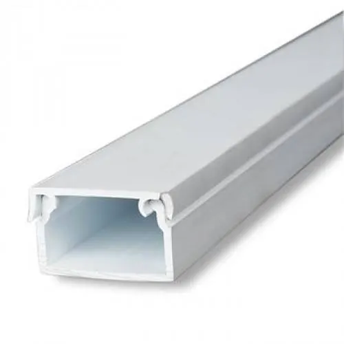
1.Trunking channel: A trucking channel is a hollow rectangular or semi-circular structure mounted on the base unit to give strength and support to the units that are to be mounted.
2.Base Plate: It is the surface of the base unit where all the units are fixed. The base plate acts as a supportive structure that is firmly attached to the fixture.
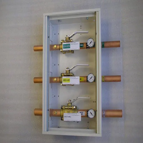
3. Valve box: The pneumatic operations valve are placed in the box and it is attached to the base unit.
4. Measuring hole cover: These are reference holes, from which the X, Y and Z coordinate data are taken.
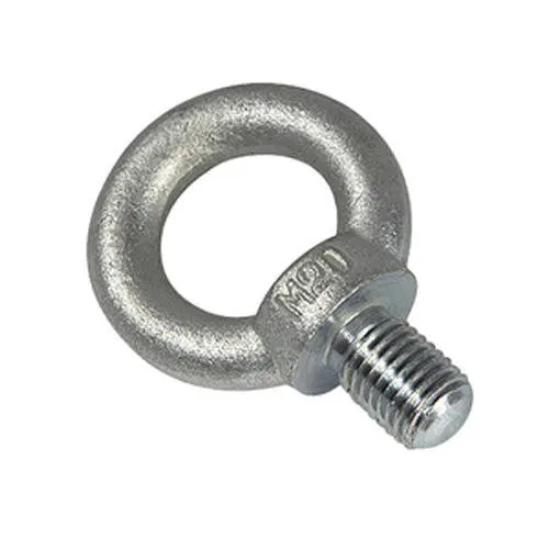
5. Eye Bolts: Used to lift and place the fixture in different locations.
6. Pedestal: These are the supporting structures to the base plate from the ground. It can be adjusted to the height of the designer.
7. Weld bar
8. Floor panel: It is used to mount the fixture at a particular location.
18. What is a Dump Unit and what are its functions?
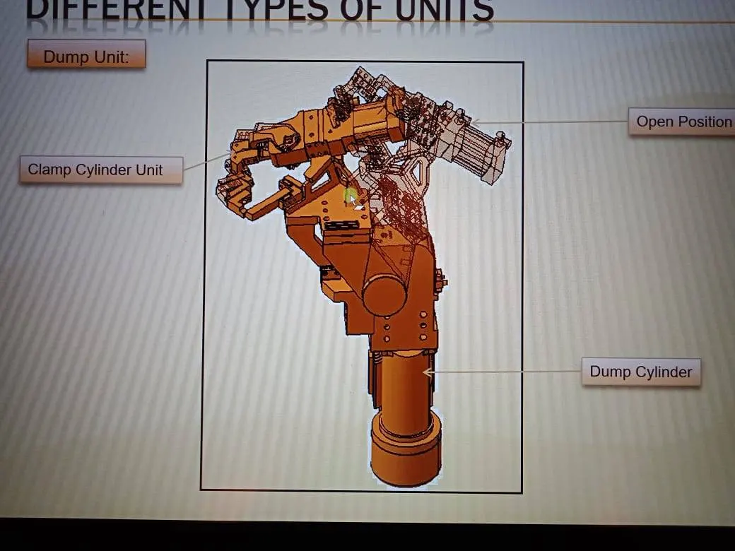
Ans: It is a complex unit to design due to space constraints there is less space available & have to adjust all the parts in available space. It consists of a dump cylinder to perform the operation of clamping & unclamping car panel. If there are any geometrical constraints dump unit can be used.
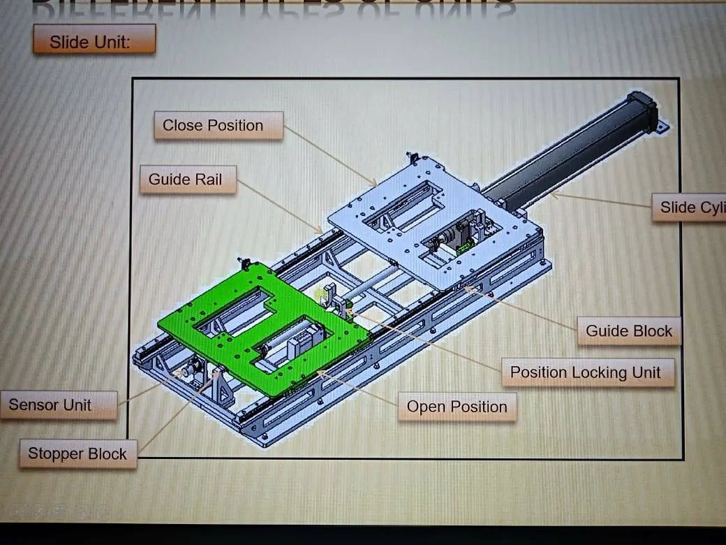
19. What is a Slide unit? Mention where Slide units are commonly used.
Ans: 1)Slide units are positioning units that are used to position the ar part, fixture, weld gun robots into position for further operations.
2) Slide units may be classified into two types based on the type of guide-ways used as hardened guide way and LM guide way.
3) Slide units may further be classified into three types based on the prime mover used as manual slides, Hydraulic/pneumatic slides and CNC slides.
4) It may be further classified as Horizontal, Vertical and Angular slide units depending on the application.
5) LM guide ways are preferred over hardened guide ways due to the least co-efficient of friction.
6) Slide unit essentially consists of LM guides, linear cylinder, front and rear stoppers, front and rear shock absorbers, two proximity switches/reed switches for sensing the two end positions, bellows or protection covers for rails.