2D meshing of hood model in ANSA
AIM -To check for the geometrical errors and mesh the hood model with the given element Quality criteria
PROCEDURE -
1. In mesh deck – assign perimeter and macros length as 1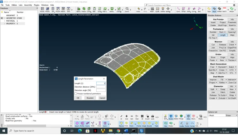
2. In Topo deck run topo command to ensure stitching of all the faces
3. Check orientation -
Before -
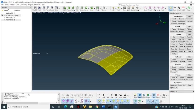
After -
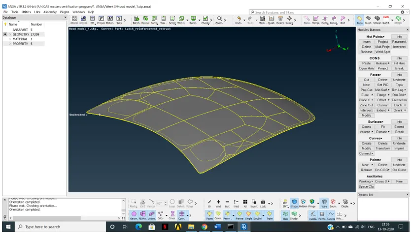
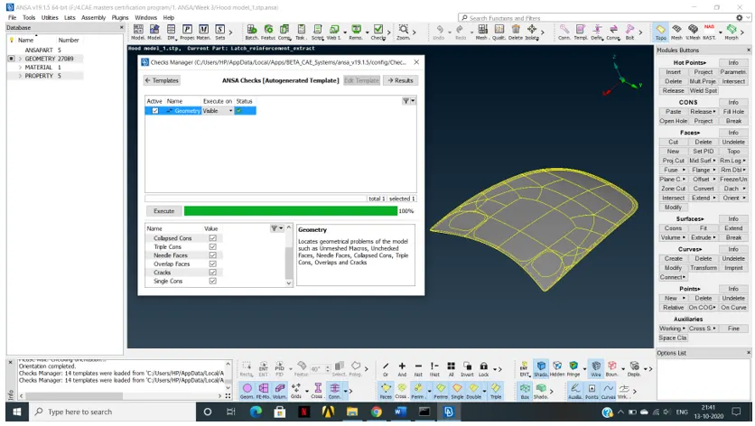
4. Run check geometry –
Before -
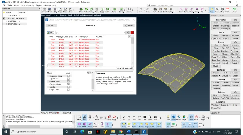
After – (Run auto fix command to remove all the geometrical errors)
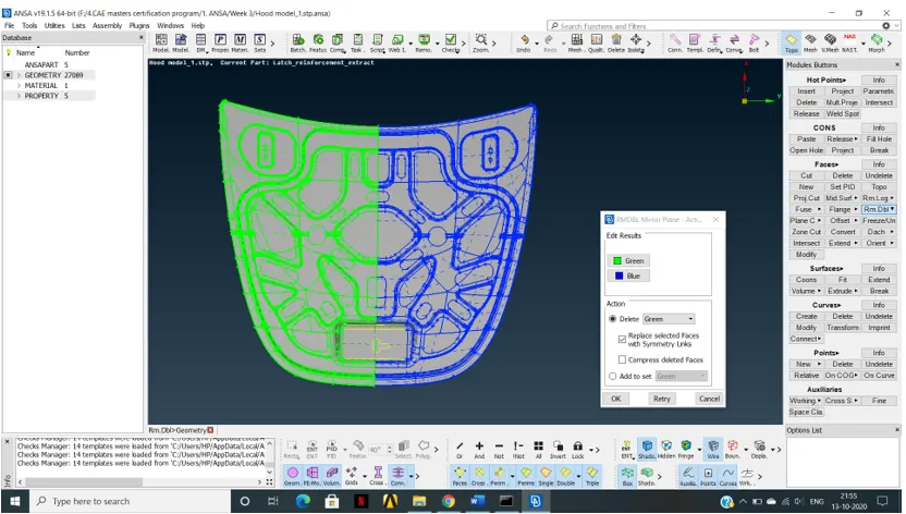
5. Use rm dbl command to check geometry symmetry
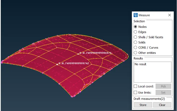
6. There are 5 properties in the given geometry –
a) lower hood panel – ID – 577, thickness – 0.75mm
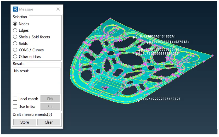
b) upper hood panel – ID – 578, thickness – 0.75mm
c) side latch 1 – ID – 579, thickness – 1.2 mm
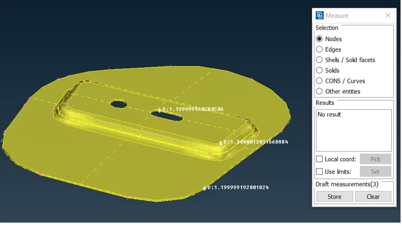
d) side latch 2 – ID – 580, thickness – 1.2 mm
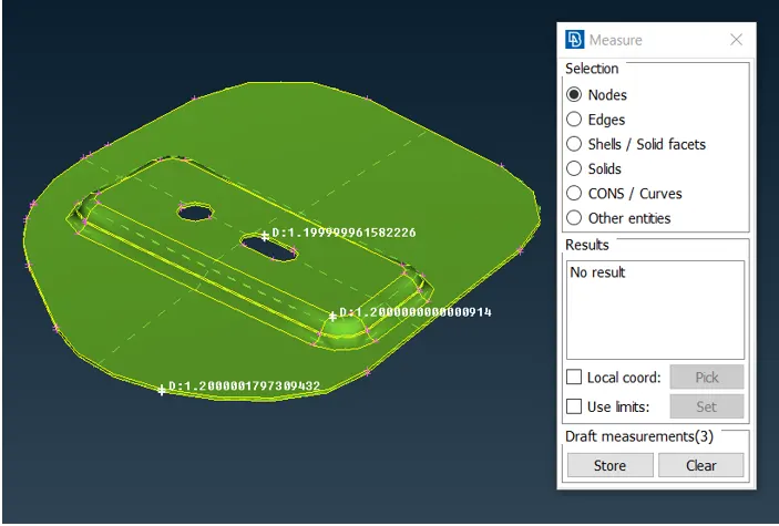
e) central latch – ID – 581, thickness – 1.2mm
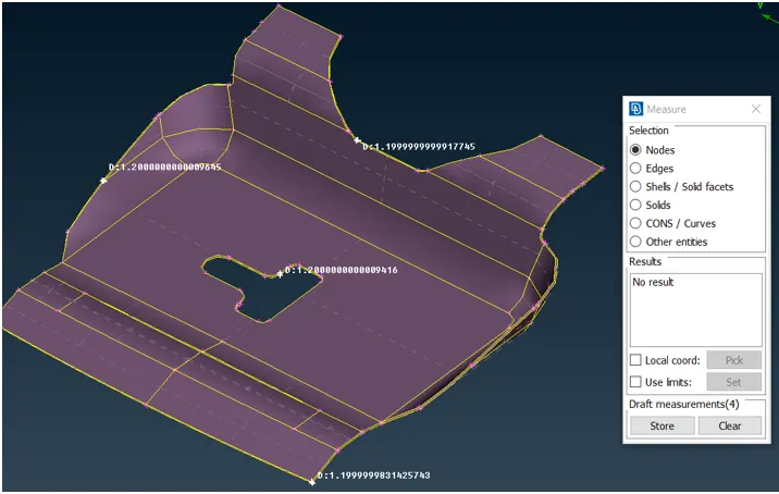
7. Now we will proceed for manual mid surfacing for each property one by one.
a) mid surface extraction for lower hood panel –
use offset faces option in topo module using feature selector to select the face and offset the faces by 0.375mm. Then we use I NOT option and neighbour all option to visualise mid surface.mid surface of lower hood is shown below –
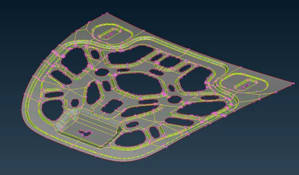
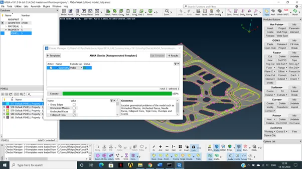
Run topo on this extracted surface and check whether all the single and double cons are proper. Ideally it should have single cons at the outermost perimeter and double cons at inner perimeters. Use check geometry option, uncheck single cons and execute –
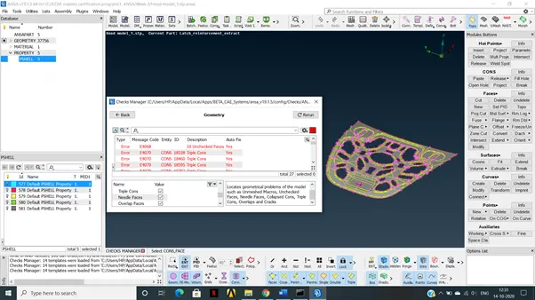
Use auto fix option to clear geometry.
Now assign property ID using set PID option –
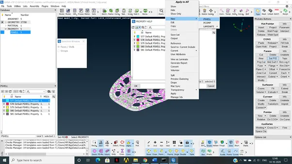
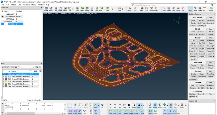
Name the Pshell property as ‘lower hood mid surface’ and assign thickness as 0.75mm.New property is created with ID as 576 , material as default material and thickness as 0.75mm as shown below –
b) mid surface extraction for upper hood panel –
use offset faces option in topo module using feature selector to select the face and offset the faces by 0.375mm. Then we use I NOT option and neighbour all option to visualise mid surface.mid surface of upper hood is shown below –
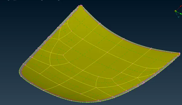
Use check geometry option, uncheck single cons and execute –
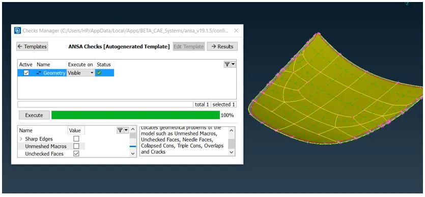
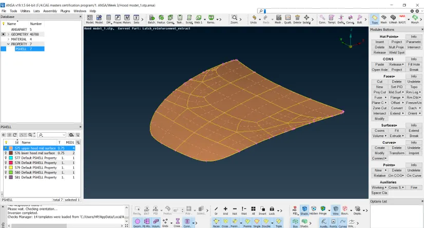
Since the geometry is clear, now we will assign property using set PID option.Name the Pshell property as ‘upper hood mid surface’ and assign thickness as 0.75mm.New property is created with ID as 575 , material as default material and thickness as 0.75mm as shown below –
c) Mid surface extraction of all the latches.
use offset faces option in topo module using feature selector to select the face and offset the faces by 0.6mm. Then we use I NOT option and neighbour all option to visualise mid surface.mid surface of latches is shown below –
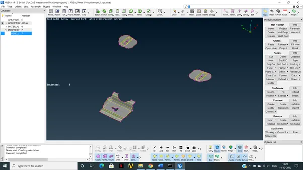
Check for any geometrical errors –
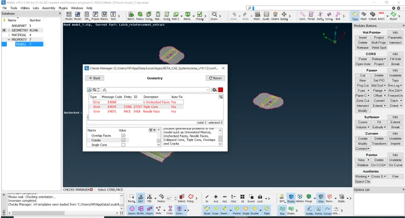
Remove these errors using autofix option.
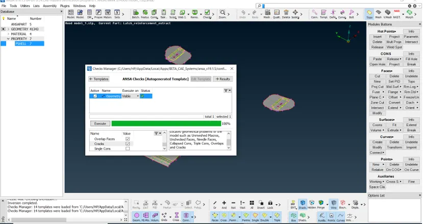
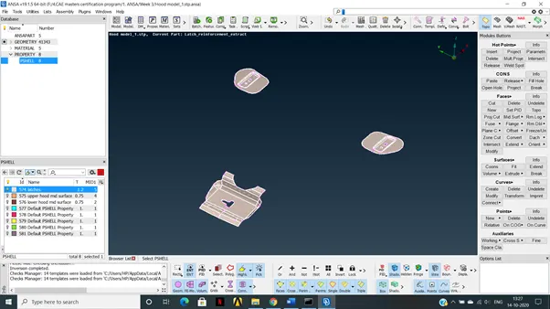
Now our mid surface geometry is clean.We will assign them as a single property using set PID option. Thickness of 1.2mm is assigned and the property is named as latches with property ID as 574. Mid surface geometry of latches with separate PID is as shown below –
8. Use auxillaries à Fine command to convert the distorted features into their original shape.One example is as shown below.
Before -
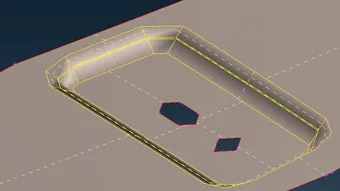
After -
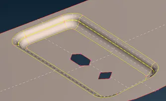
9. Meshing of upper hood mid surface
a) set the hot point spacing of 5mm on perimeter and macros.
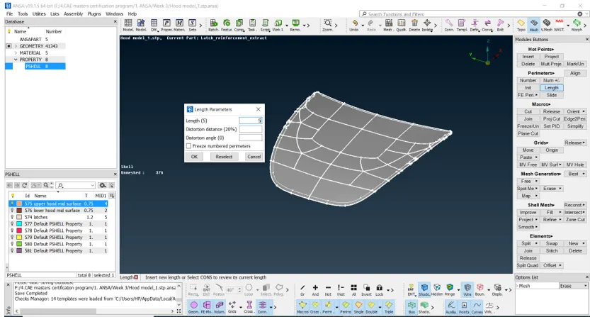
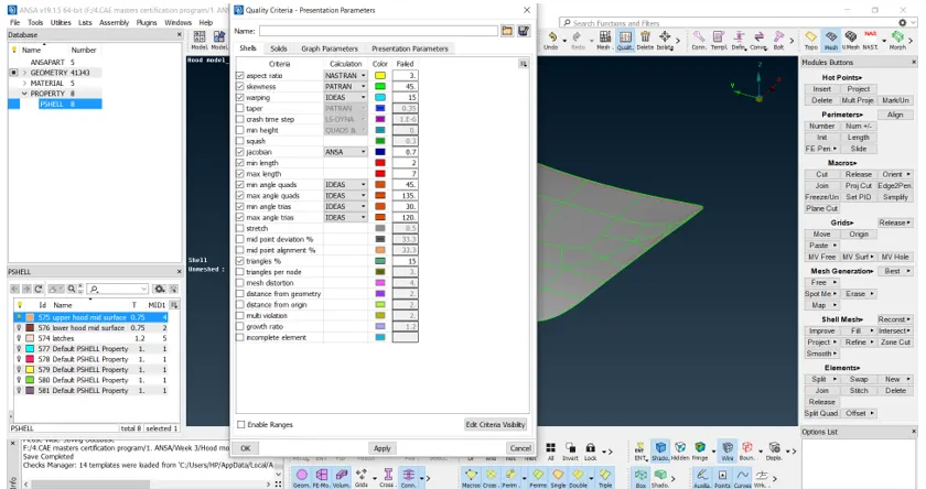
b) Set the quality criterion as per given problem statement –
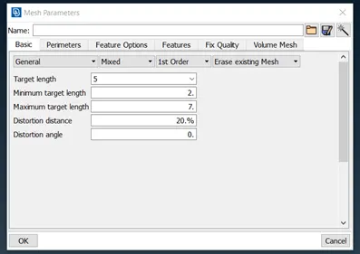
c) set the mesh parameters as shown below –
d) elements will fail in the area where the sheet metal is hemmed.
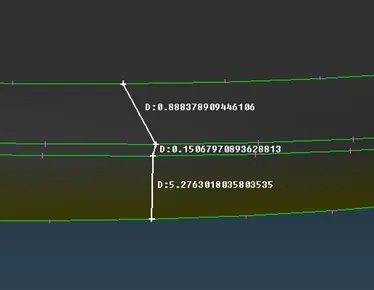
Hence we will join the macros to prevent element failure.
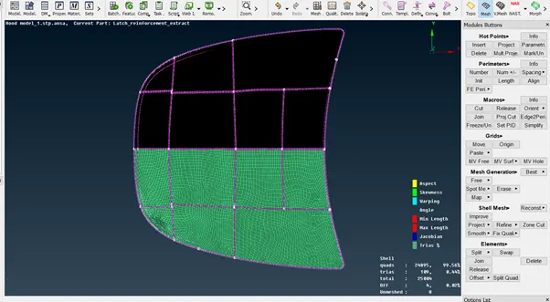
e) cut macros for better mesh flow and do meshing for half portion using best mesh option
f) use split option to remove trias near free edges –
Before -
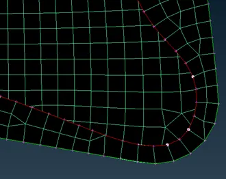
After -
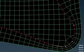
g) use of paste option to remove opposite trias –
Before -
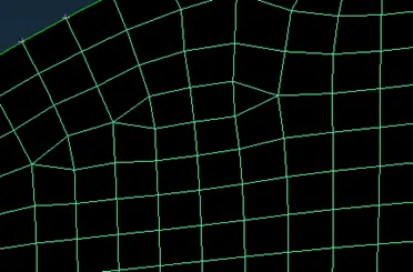
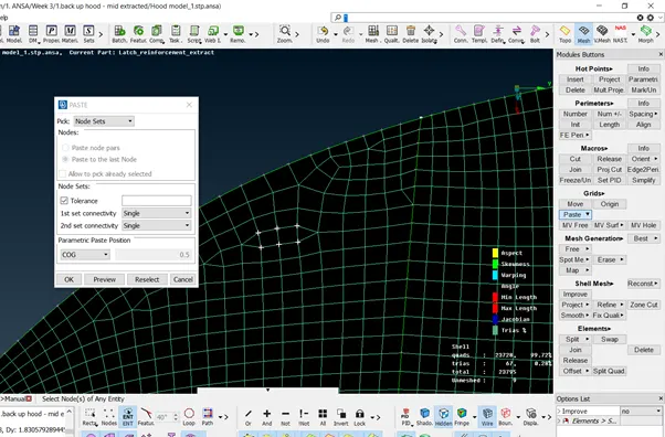
This is how we use paste option –
After –
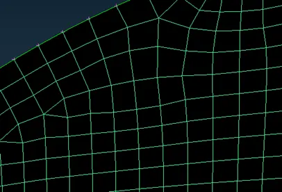
h) Half symmetrical area of upper hood is meshed and is free of opposite trias, rotating quads and distortions. It is also satisfying the quality norms.
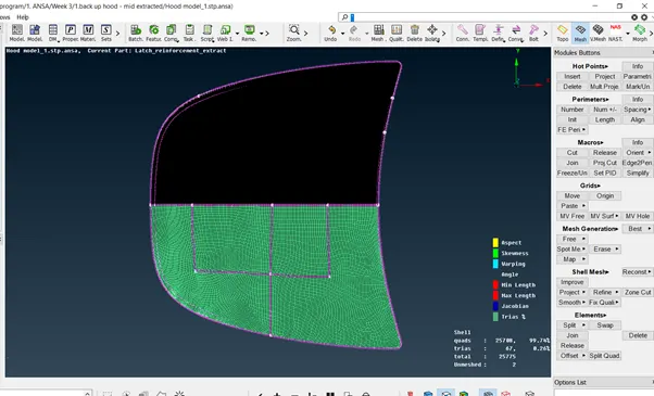
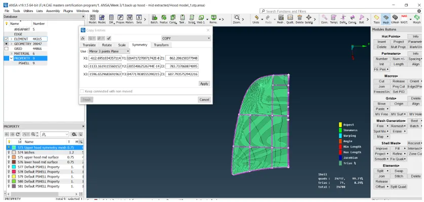
i) Now we will proceed for symmetry option. For this we will first cut the other half of the symmetrical hood and then use symmetry option as shown below –
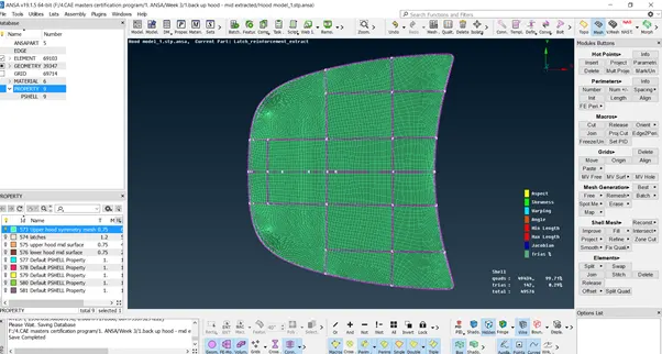
j) Final meshed upper hood surface is as shown below –
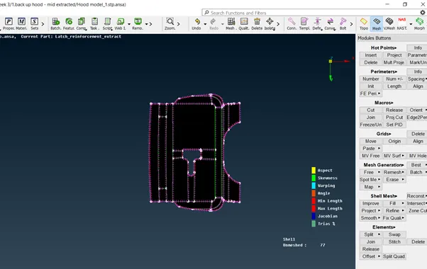
10. Meshing of central latch.
a) First we will make some cuts on the faces to get a better mesh flow
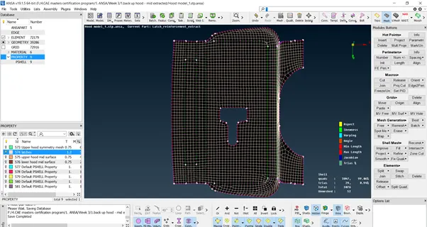
b) Now we will perform best mesh and remove all the rotating quads, opposite trias and trias near free edges and perimeter using split, paste, edge to remove and smooth options as discussed during meshing of upper hood surface.The final meshed model is as shown below –
11. Meshing of side latches
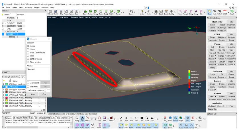
a) To avoid elements quality failure for minimum length, delete the cons at the middle as shown below -
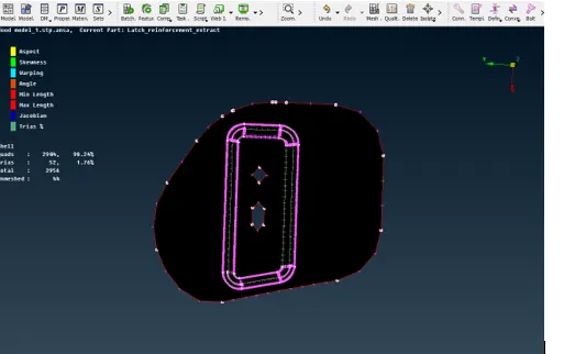
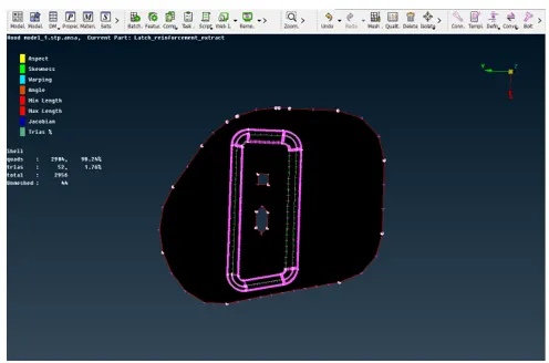
b) Now we will align the hole parallel to the perimeter lines using perimeter -> Slide option and then mark it.
Before -
After -
c) Now we will mesh the surface using best mesh and improve mesh quality by removing rotating quads, opposite trias and trias near free edges using reconstruction, smooth, split and paste options.
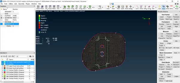
d) Now we will use symmetry option to copy this mesh for the symmetrical latch on other side.
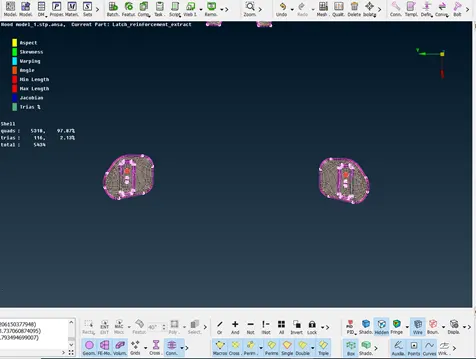
12) Meshing of lower hood surface
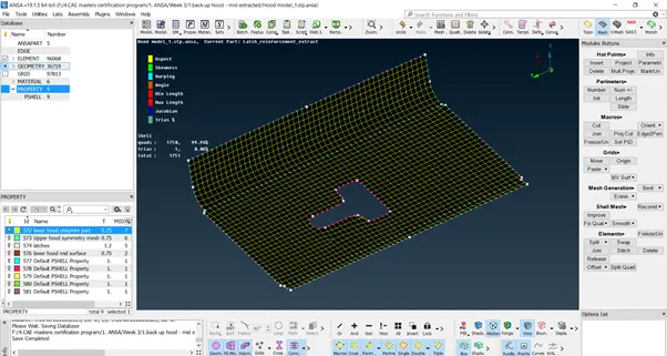
a) First we isolated the unsymmetrical face in lower hood surface and set it as a different property having property ID as 572. Then we run the double command to check the symmetry of the remaining faces of lower hood surface.
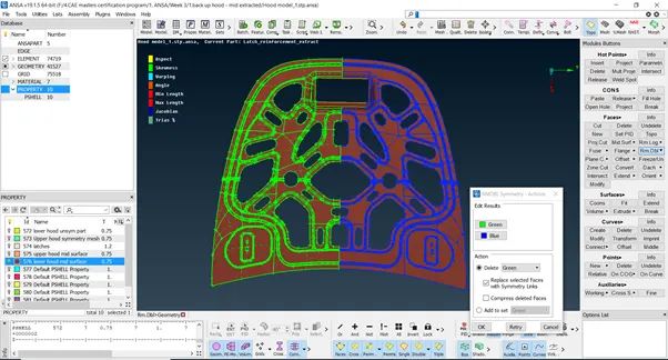
Since rest all faces are symmetrical hence we will mesh only half portion and then later use symmetry option to copy that mesh on other side.
b) Delete the half portion of the symmetrical faces
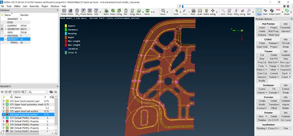
c) In this geometry there are many feature lines which can cause element failure. Thus we will delete those feature lines and also try to capture those features.
d) Now we will mesh the surface using best mesh and improve mesh quality by removing rotating quads, opposite trias and trias near free edges using reconstruction, smooth, split and paste options. We also have to ensure a proper mesh flow. After improving the mesh it is looking like this with no off elements–
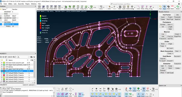
e) Now we will use transform symmetry option
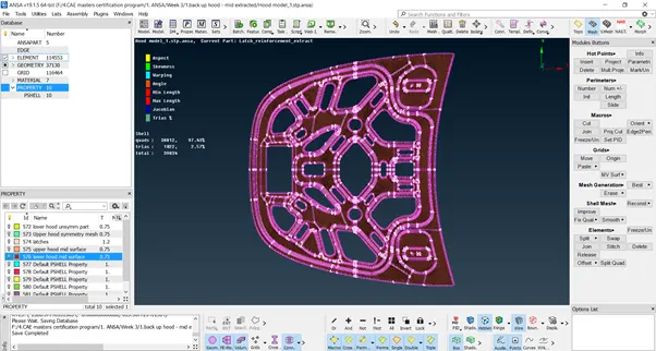
f) Now we will mesh the unsymmetrical faces of lower hood –
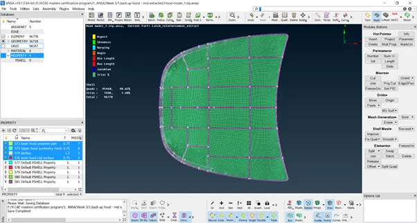
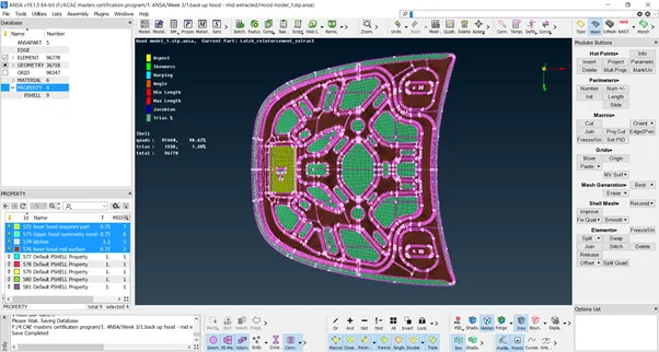
13) The meshing of hood model is complete and the final meshing looks as shown below –
LEARNING OUTCOMES –
1) Whenever there are curved surfaces there will be trias near them. If we try to remove those trias, it results into rotating quads. Hence those trias should not be removed, but at the same time it should be ensured that those trias are not falling near the free edges and perimeter lines.
2) If opposite trias are far enough from each other then there is no need to go for split option otherwise it will reduce the mesh size and we wont get the average length.
3) edge to perimeter is a good command to remove quality error and at the same time maintain the geometry features.
4) Important feature cons like those near fillet should not be deleted else our mesh wont follow the geometry profile.
5) After meshing, first we can work on off elements and then improve mesh flow to save time.
6) Always check for symmetric faces. It saves lot of time.
CONCLUSION –
1) Final mesh model contains 98.62 % quads and 1.38% trias.
2) All the elements in the model cleared the mentioned quality criteria and the features in the model have been captured properly with good mesh flow.
3) There are no rotating quads and opposite trias in the model.
4)Trias near to free edge or holes or on the fillets have been eliminated.
5) There are no OFF elements in the model.