2D Meshing of Hood in ANSA
AIM: To create a 2D mesh in the HOOD of a car according to the given quality criteria.
PROCEDURE
The given component is a hood model which is also called bonnet of a car. This part is a sheet metal part and so that thickness is very low. So instead of going for 3D meshing, We can go for 2D meshing. For that we need to extract the mid surface. The hood is having 4 separate parts, which are hinge reinforcement, Latch reinforcement, a inner panel and an outer panel. So we should extract the mid surface of each of these 4 parts before meshing.
WHY we carry out meshing?
The answer is because the original component is having infinite number of atoms in it and when we apply any force the displacement or strain is happened to each and every atom inside it. but infinite number of displacements to find out is impossible. So we need to make the calculation finite. for that we divide the component into a finite number of elements having finite number of nodes. Most useful and popular 2d elements are quad and trias. Trias are being stiffer compared to quads they hesitate to transfer the force applied on it to nearby nodes so they are to be needed to minimize in the meshing process. Each element is having lines at the outer boundary which is based on the specific shape function of the element. We can find out the values of stress and strain at the nodes of the elements. Since we know the shape function of the element we can find out the displacement and stress values at the particular x and y as we need using the shape function.
For QUAD4 element shape function is u = a0 + a1x+a2y+a3xy.
FEA will calculates the values at nodes ,ie = a0,a1,a2,a3 Value of the variable in between nodes can easily be find out using the above shape function. Each element will have several degrees of freedoms. Degree of freedoms is the number of variables with which the position of a node can be represented perfectly. Mostly the total number of degrees of freedom = total number of elements x 6. since the 3 linear motion and 3 rotational motion along x,y,z axis are possible for each and every elements. Then the degree of freedom also depends on the type of Analysis we are to be carried out, Type of element we used in meshing process. Higher number od nodes in the mesh means higher accuracy. But the computational time will be high. Computational time is directly proportional to nth power of the Degree of freedom, and n = 1 to 4 depending upon the solver we used for analysis.
The cad model needs to be imported into the ANSA GUI.This is done by File>Open>select the CAD File>open.Then the cad file will be opened in the ANSA.Since the platforms are different for CAD and CAE there will be so many translational issues in the model imported,So we need to first topologically cleaned up the hood component.To topological clean up of the model we need to stay in TOPO Module and use the necessary options in the TOPO Module.Before that check the topological errors occurred due to the platform change by the use of check manager in ANSA.For that go to Check Manager>Geometry >Execute.It will show up the topological issues in the Model.We can go to each part and rectify the issues.The options used are
CUT : This is used to make the lines in the model which will divide the entire model.Face>New>Fitted>select the cons of the geometry to be created.
Zone cut is used to provide washers about the small holes.
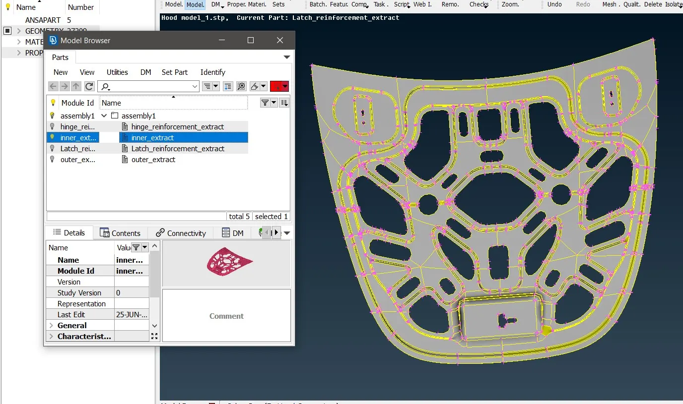
Fig 1 Geometry check of Inner extract panel
Then the next step is to extract the midsurface of the component.Here for this component we can go for automatic midsurfacing.Midsurface of every part can be extracted using the midsurface>Skin>select the component to be midsurfced>Middle click ,this will gave us the the midsurface of the component.One side of the component will be shown in red and the otherside will be green and the thickness will be blue,this is basically the view provided by ANSA when we try to take midsurface.If anything wrong with the colour ,then we should manually change the colour.
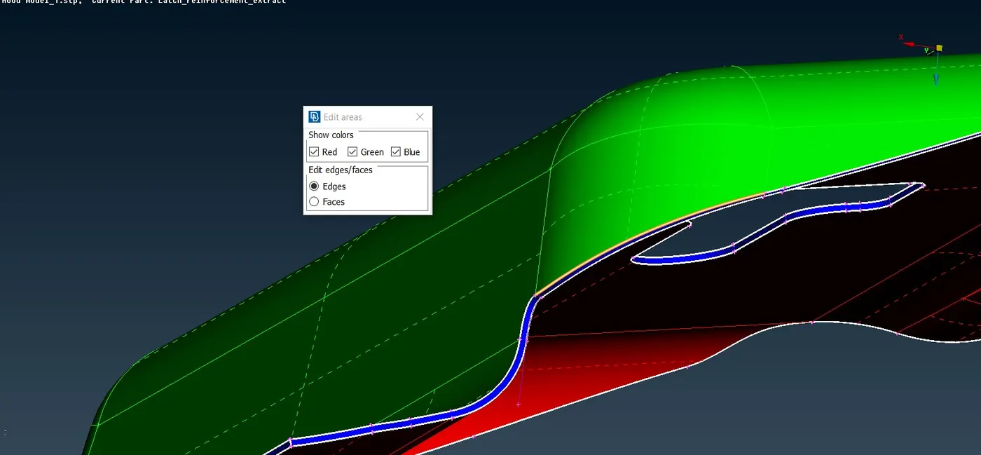
Fig 2 Midsurface colour pattern
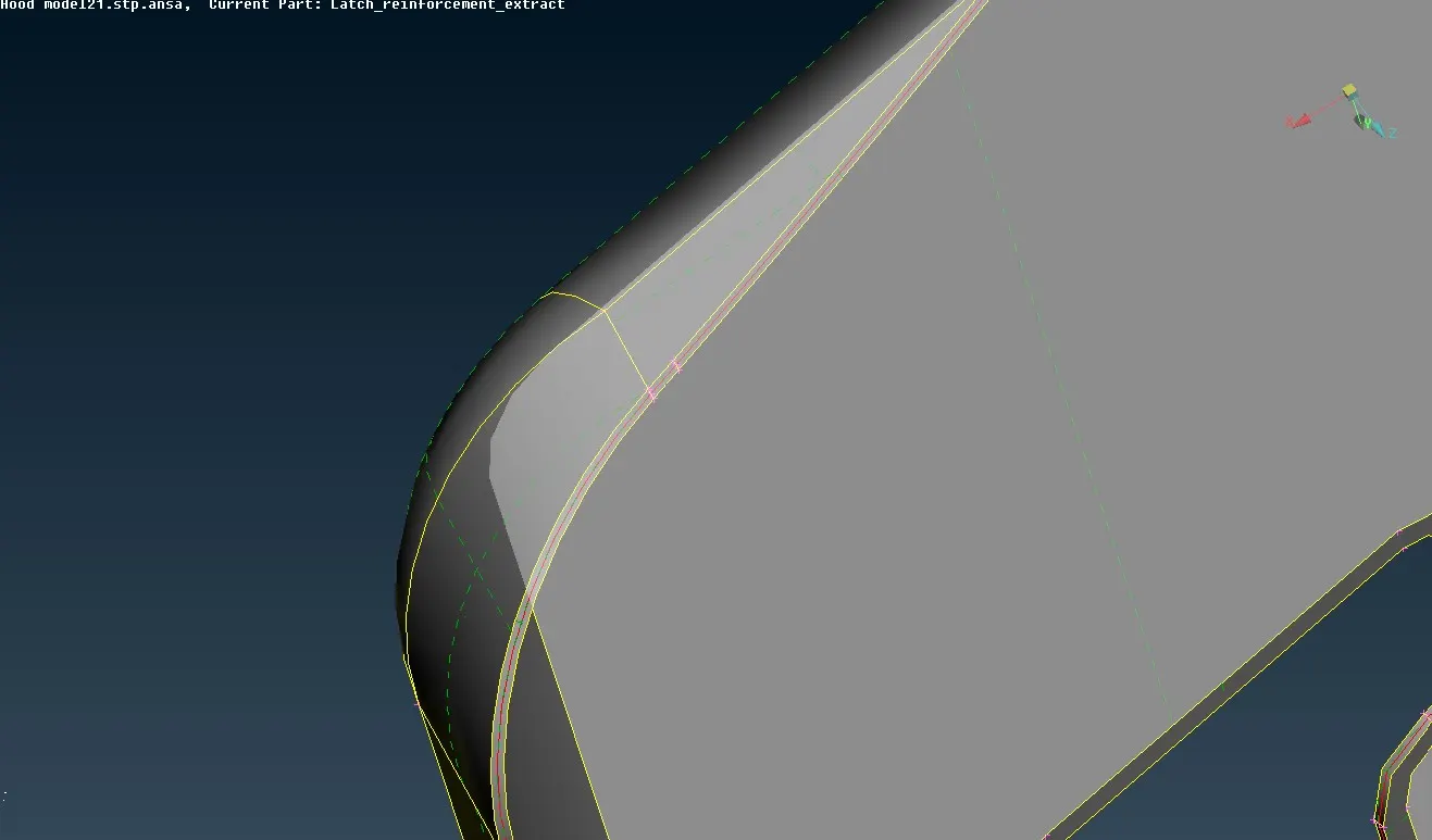
Fig 3 Red lines in between the outer and inner surfaces shows the midsurface
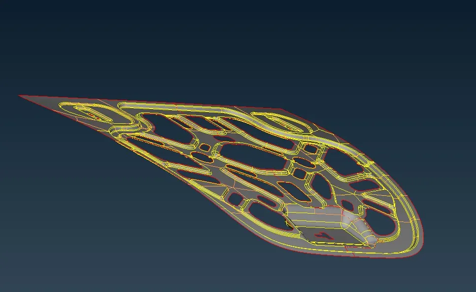
Fig 4 Inner Panel Midsurface
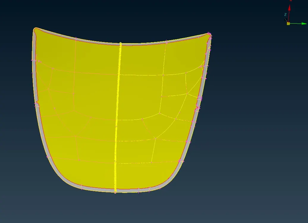
Fig 5 Outer Panel Midsurface
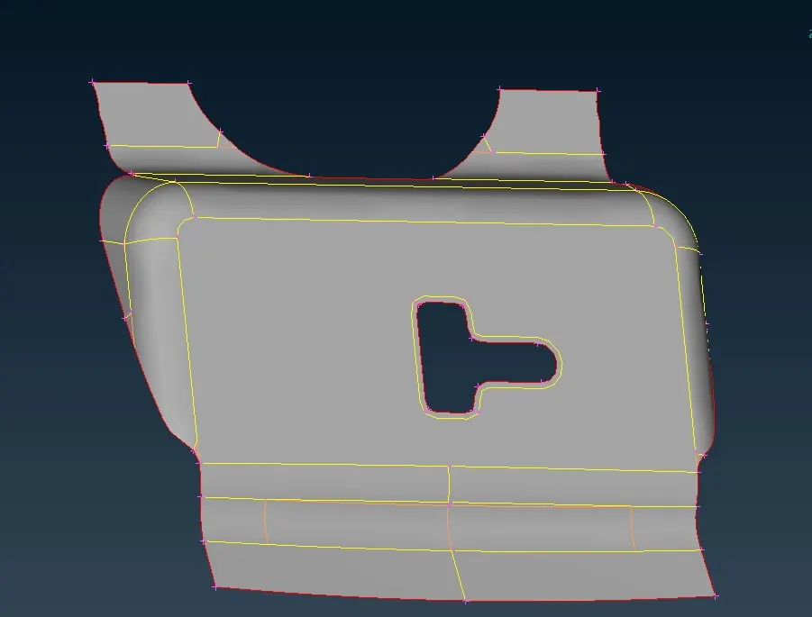
Fig 6 Latch Midsurface
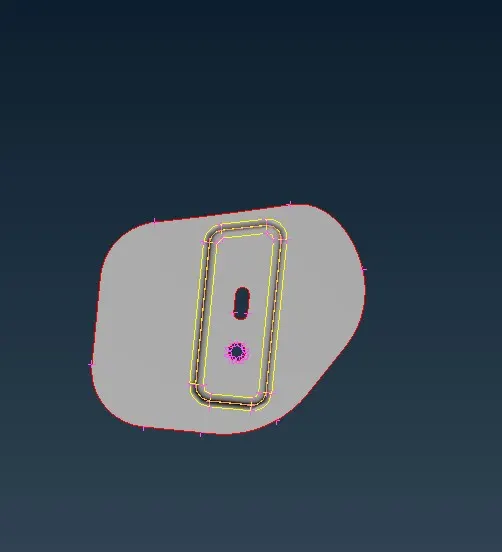
Fig 7 Hinge reinforcemenet Midsurface
After the midsurface extraction of each component,we need to look closely into the midsurface of the component and look for sharp edges in the component which will make our elements fail for minimum element size.Here the element minimum size is 3 mm.So check for sharp edges and remove it by cut the sharp edge interaction by using the cut option.For measuring the distance we can use the measure option in utilities panel and select the two nodes in between which we need to find out the distance.Then ANSA will show us the distance.
Then we can move on with the mesh generation.For this we need to move on to MESH Module.And we need to set the quality criteria in the utilities panel.In utilities panel there is an option called QUALITY ,Select Quality and check the relevant boxes like aspect ratio,Warping,skewness,Jacobian,Minimum and maximum length of elemenet,Minimum and maximum angle of quad,Minimum and maximum angle of trias,Pecentage of trias and edit the each one of the values with the desired values.Then click on apply.We need to change the view to HIDDEN view mode to see the failing elements while meshing.So go to the hidden View mode and starts to mesh.We can mesh surface by surface ,For that we can make use of the BEST option under the mesh generation panel.This option has the best algorithm for the different shapes of the surfaces.And if we are not satisfied with the mesh produced then we can reconstruct it using the reconstruct option in the Mesh generation panel.We can select the tool reconstruct and select the surface mesh using the MacroArea selection mode and and middle click.Using rerun option in reconstruct we can change the mesh and we can select the best reconstructed mesh. For the components which are symmetric we need to only mesh the half of the total area and we can make use of the symmetry option for completely reflect the the half mesh for the other side.
After reflecting the elements we need to ensure the connectivity between the orginal mesh and the reflected mesh .For this we need to go to the BOUNCE View mode and we can see the red lines which shows there is no connectivity.So we need to make use of paste option to manually connect each such elements.Then check in bounce mode and ensure there is no unconnected elements in the mesh.
Various things to keep in mind while meshing are;
- If there are any opposite trias ,we should re-mesh these trias and thereby we can remove those trias.
- There should not be any mesh transition at the fillet regions.
- Smoothing command can be used to smoothen the mesh. until we get even mesh flow.
- Never place TRIA elements at the edges or inside the washer.
- Adjacent TRIAS must be removed.
- Rotating Quads are not acceptable in CRASH TEST but acceptable in structural analysis. Same directional following TRIA elements are acceptable in CRASH ANALYSIS but not permissible in structural analysis.
- Always mesh the component keeping in mind the quality requirements.
- Trias should not be present at the edges of the component and should not be orginated from the perimeters of any feature.
After meshing each component based on our quality requirements, we need to release the mesh from the CAD model.For that go to the elements option>Release> select the entire mesh and middle click .This will release the mesh from the CAD model.So that any change in the CAD model will not be reflected in the Mesh.We can see the mesh using the FE mode.Then we need to assign the thickness to the mesh.This can be done using assigning the thickness to the mesh.When we make midsurface,ANSA will create and assign a property with the midsurface.So we need to edit the property and give the thickness as same as the component thickness.Outer panel and inner panel extract is having thickness of 0.75 mm and the latch and hinge reinforcement is having thickness of 1.2 mm.We can assign the thickness to respective component using assigning property option.
RESULTS
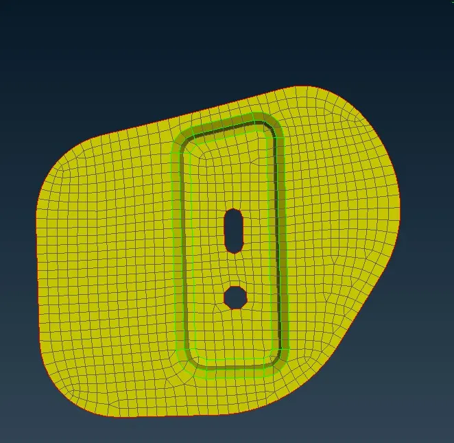
Fig8 Hinge reinforcement meshed
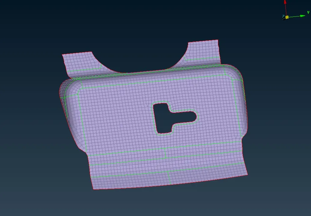
Fig9 Latch reinforcement Meshed
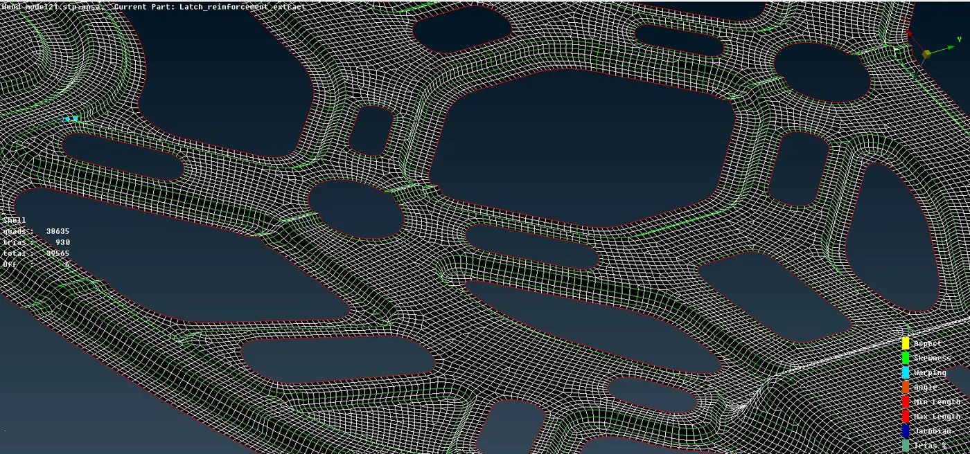
Fig10 Inner extract Meshed
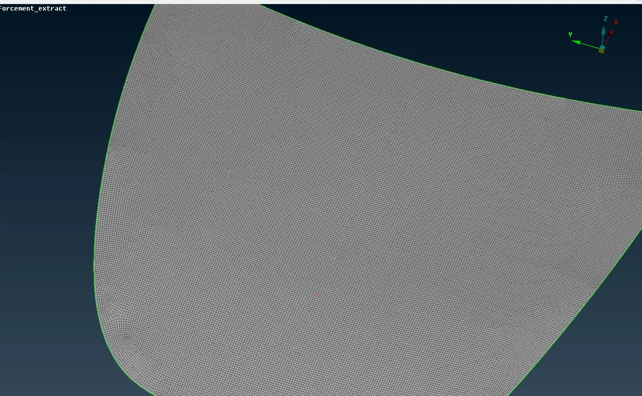
Fig11 Outer Panel Mesh
CONCLUSION
Some regions of the componenets we cannot follow the quality criteria like the folding happens in outer panel for hemming connection.In such cases we need to capture the features properly so we make compromise on the quality criteria.Even if some elements fail for minimum length there will be nodal mass scaling technique to ensure proper timestep in the dynamic analysis,So some elements failing for the minimum length is fine and the percentage of failing of elements for minimum length is dependent on the organisation.
Link for the files
https://drive.google.com/file/d/11_dFc6ppBqTLtY6koUVoW9KK_GmbcBRm/view?usp=sharing