Week 3 - 2D meshing for sheet metal
Aim-
Take the mid-surface for all the components of the given hood model and mesh the mid-surface with the given element quality criteria.
Procedure-
There are three main procedures to follow meshing 2-D sheet metal as follows-
- Geometry Clean up.
- Mis-surface Generation.
- Shell Meshing.
1.Geometry Clean up-
The CAD model we upload in ANSA has certain geometry flaws in CONS and hot points while converting files into .stp formant or human error of CAD designer. Its duty of CAE engineer to clean all geometry errors before doing mid-surfaces.
Steps to follow-
- To conclude the given part is sheet metal, open PID separately and measure the distance between any random two CONS and Check distance lies throughout model (0.75mm)
- Initially Open Check Geometry and check geometry errors. Once executes, select all the errors and click Fix which Automatically fixes errors and issue.
- Increase the CONS resolution using Topo module>Perimeters>Length and select entire model and value of 1 instead of default value 20, click ok.
- Finally Check of Geometry errors again before going Mid-surface
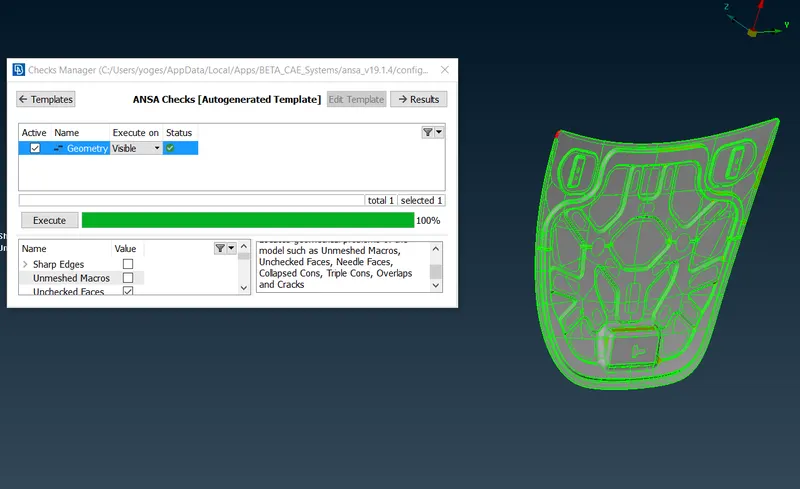
Fig.1 Geometry check
- Mid-Surface Generation.
- Assign a custom property id for given components by Using keyboard shortcut CTRL+P or click Properties tab, create a new custom ID by right click>new>PSHELL and name as mid-surface and change thickness value from 0.75 to 1.
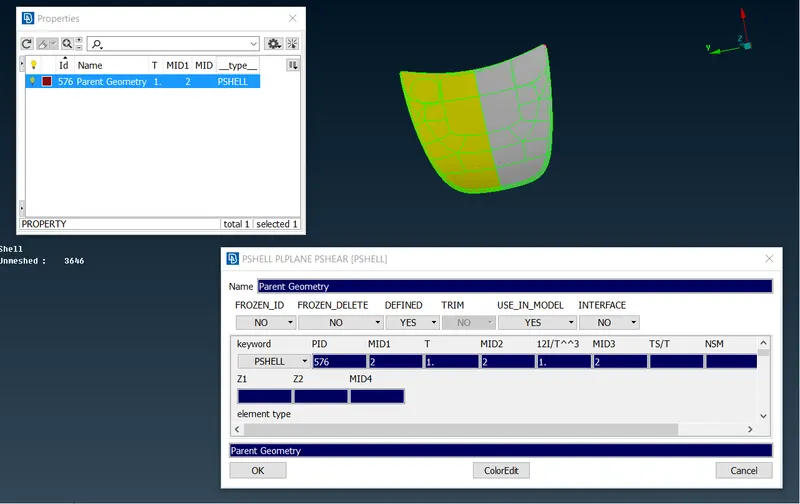
Fig.2 New PID for mid-surface
- Use hybrid !not to select mid-surface
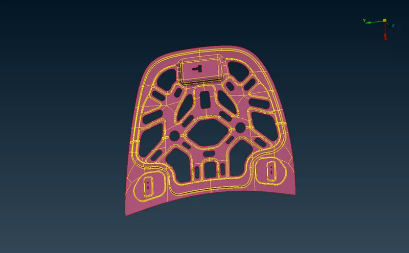
Fig.3 Mid-surface
- Extract mid-surface using both auto using Topo>faces>nidsurface and manual mid-surface using Topo>faces>offset.
- Meshing.
- Change Mesh Parameters with given target length 5mm, minimum target length 2mm and maximum target length 7mm.
- Go Mesh module and select Perimeter>Length>Perimeter and select the entire model and enter vale of 5mm.
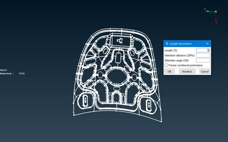
Fig.4 Length Perimeter
- Check Error in CONS over the model and rectify using Macros>cut and join, If Two or More CONS denoted the same feature, delete one of them.
- Check the number of nodes using Perimeter>number and select whole model and change the odd number to even numbers using Perimeter>Num+/-
- Finally, change quality criteria using given values as shown below.
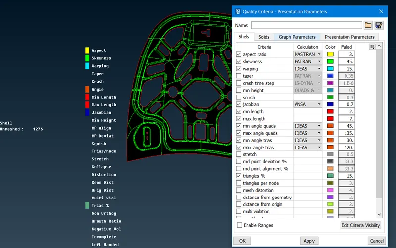
Fig.5 Quality Criteria
- Now mesh model using Mesh Generation>Best and select whole model and click hidden mode to check mech criteria
- Using Shell mesh>reconstruct enhance the quality of the mesh and manually correct mesh using Elements>split-swap
- Eventually, use Shell mesh> smooth and select the whole model for better mesh flow.
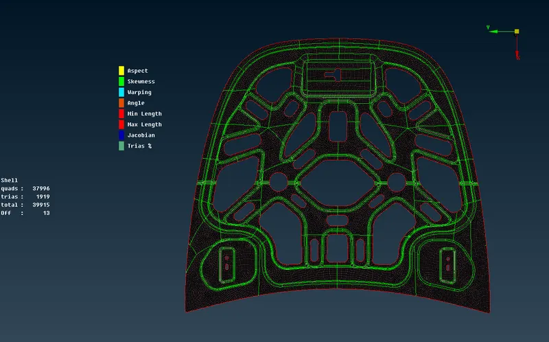
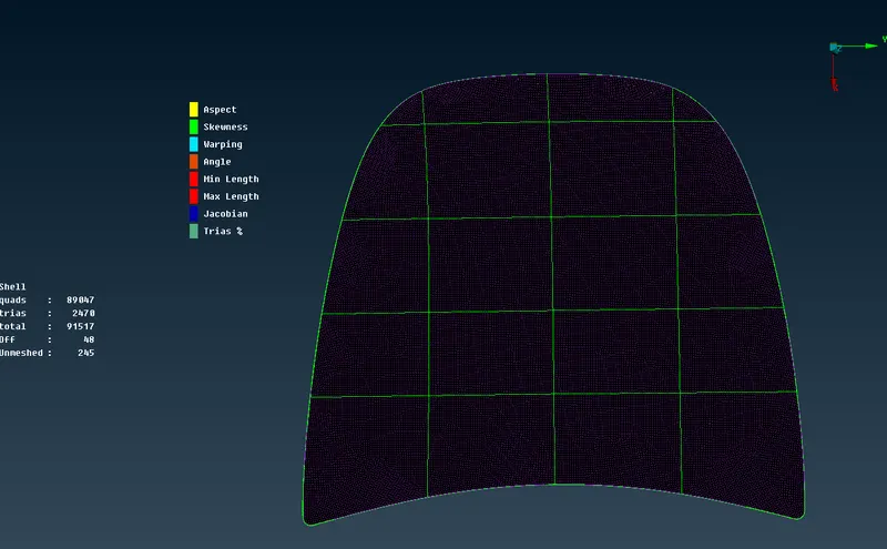
Fig. 6 Meshed mid-surface
Post Meshing results-
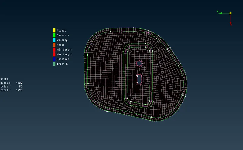
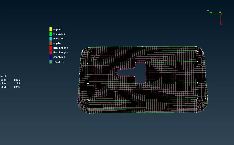
Learning Outcomes-
- Through this project, I gained experience in Geometry clean-up mid-surface extraction and meshing for Sheet metal components using ANSA.
- Wide view and confident in software and been more friendly towards options and features.
- Using auto mid surface and auto meshing I saved much time than doing in manual method.
Conclusion-
The meshing of Hood has done successfully using given quality criteria and attained proper mesh flow and model thickness.