Week 3 - 2D meshing for Sheet metal
AIM:
For the given Hood model, Take the mid surface for all the components after checking the geometrical errors and mesh the mid surface with the given element Quality criteria. Also to assign thickness to the mid surface plane after meshing.
|
S.No |
Quality Criteria |
Value |
|
1 |
Target/Average length |
5 |
|
2 |
Minimum Length |
2 |
|
3 |
Maximum Length |
7 |
|
4 |
Aspect |
3 |
|
5 |
Warpage |
15 |
|
6 |
Skewness |
45 |
|
7 |
Jacobian |
0.7 |
|
8 |
Minimum Quad Angle |
45 |
|
9 |
Maximum Quad Angle |
135 |
|
10 |
Minimum Tria Angle |
30 |
|
11 |
Maximum Tria Angle |
120 |
|
12 |
Tria Percentage |
15 |
PROCEDURE:
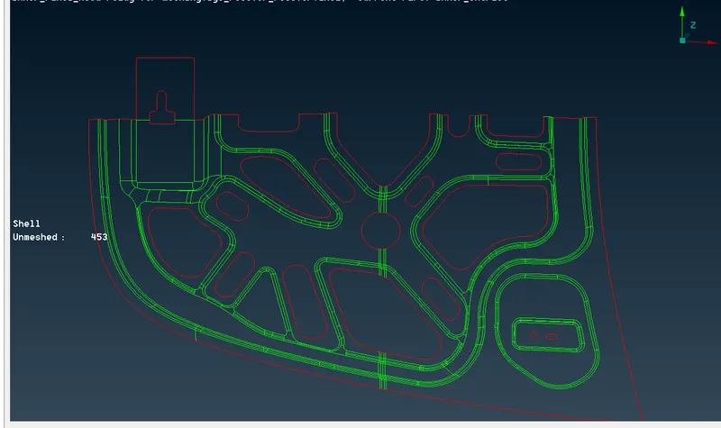
- Importing the model. as it is given that hood model of sheet metal component mesh to be created on the mid surface of the model. but before going for model surface extrusion and meshing operation it is important to perform a geometry check and if they are any errors present in the model need to be cleared. before meshing it is prime operation that errors are cleared.
- After importing the model. we need check of the surface attachment for safer side perform a TOPO operation the object, if they are any misalignments and connection errors present in the model will be attached. Also change the length criteria from the perimeter tab for getting appropriate results.
- The geometry check need to be done using tools > checks > Geometry, and clicking on the geometrical problems of the model such as Unchecked Faces, Needle Faces, Collapsed Cons, Triple Cons, Overlaps, Single cons and Cracks. Clicking on the execute option and finding the errors in the surfaces. If any errors found that as been cleared using the automatic fix option or manually cleared using the TOPO option.
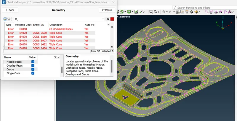
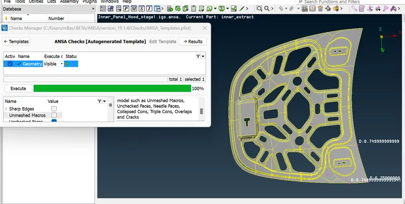
4 .After cleaning up we can assign properties and property IDs to accommodate the mid surfaces that will be created. Doing this will also make it easier for viewing components separately. To create a property, go to properties from the upper toolbar and right-click the list. Then go to New > PSHELL > PSHELL to create a new property ID.
After creating new property ID. can go for creating mid surface but before going to midsurface we need to change the parametric length of the geometry for fine finishing of the geometry.
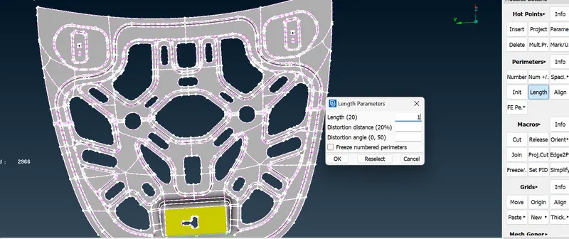
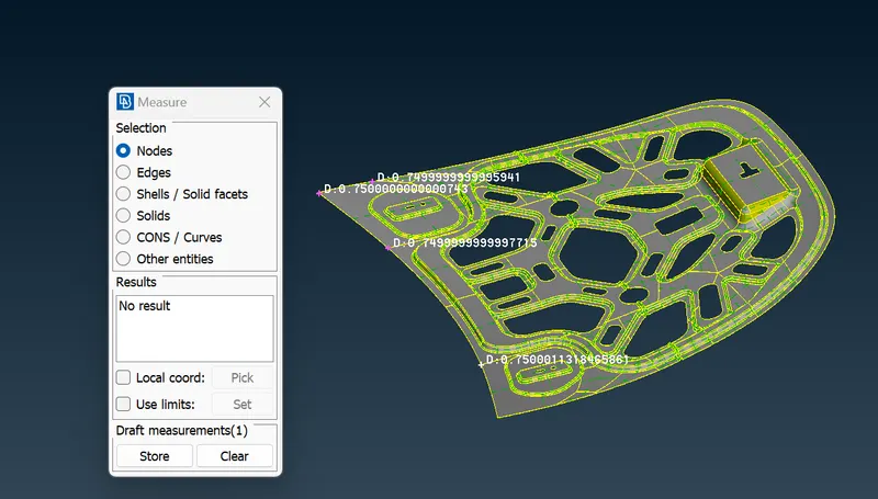
5. After giving parametric length as 1mm. Now we need to check the thickness of the component to generate the mid surface for the parent component, the main geometry is created as the parent geometry. we need to check the thickness of the geometry at different areas to check that all out the component that the thickness is equal or not.
6. Now, we can generate the midsurface of each surface. This can be done using the 'midsurface' tool in the faces menu or using the 'offset' tool from the Topo module. The midsurface tool would be ideal here as the components have a constant thickness. The offset tool would be more effective in cases of varying thicknesses. For practice purposes, I went with the offset tool.
After selecting the offset tool, it will ask us to select the surfaces to offset. We can select the surfaces on one side of the component. After that, we can assign the offset value (half the thickness).
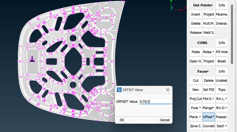
7. After giving the offset thickness for the mid surface generation for the parent component and aster selectiung the aresa on the parent component te direction opf the arrow is to checked. and the check with the property and part section, it should save in the property that we are created.
After giving the value for offset the mid surface is generated. mid surface is generated foir the comonent . it may take some time depending the complexicity of the geomentry.
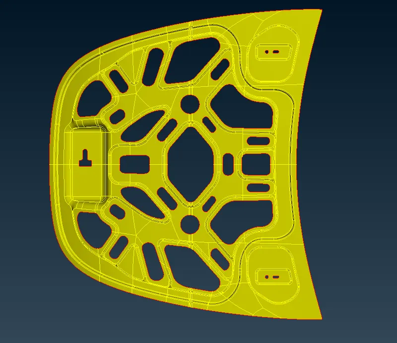
8.After the mid surface is generated, we need to check the geometry to in the safer side to save our time, their is a chance of creating errors while it generating the midsurface for the component. make sure that single cons are deselected in the geometry check
9. Now need to give quality criteria for the component as we are recommended to follow and also mesh parameters are also need to be assigned for the geometry.
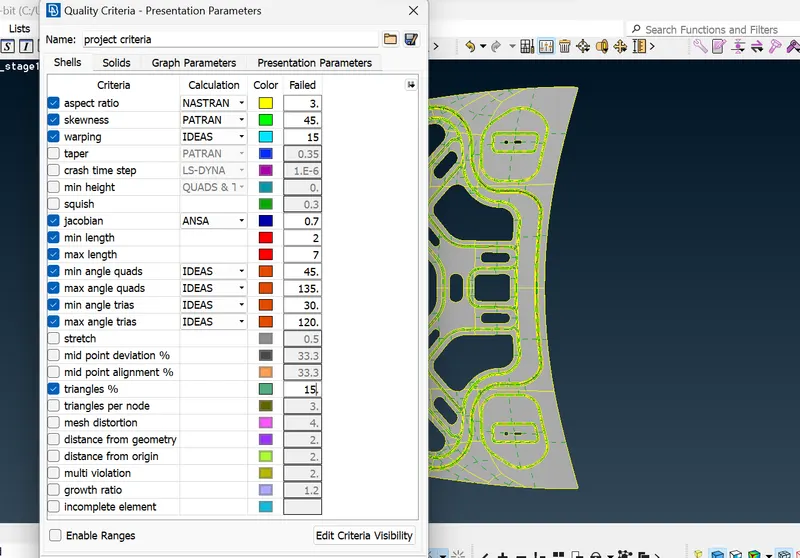
10.If the given geometry is symmetric we can save a lot of time by meshing the single side of the geometry for that we need to create a mid-plane and cut the other side of the geometry from faces table in topo module. after cut the symmetry part from the component. check for the geometry now we can go for mesh module but before going for the mesh we need to change the parametric length of the geometry to 5mm that we are recommended.
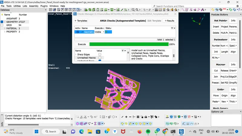
11.Now we can mesh the mid surface in order to mesh we ned to check the geometry that it is satisfying the given quality criteria and mesh parameter by using the scale tool. We need to go though the all the part of the geometry.
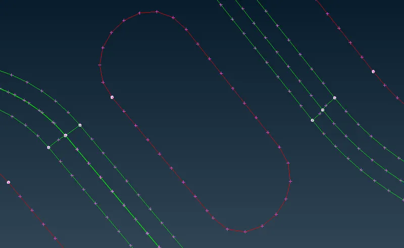
12. For the circles try to maintain the even number of the division to get good mesh for the component and check the other parts specials curve and circles are need to be checked twice.
13. now try to mesh the component. for meshing we need to use tool mesh generating table the tool suggested for good mesh for beginners is best mesh, now select the part by part of the component, make sure that first mesh the area that is complicated then go for the easier areas that is plane areas. mesh all the part.
14. The are or grid which is failing for the quality criteria is shown as follows when we select hidden mode in the work space. now we need to clear the errors by using smoothing and Ramesh and split the element tools by using this tools we can solve the errors in the elements. try to generate the mesh flow in a uniform throughout the component and try to eliminate all the possible trias and the tris in the any face should be in the any two directions it should not exceed more then two directions and they should not be in opposite direction.
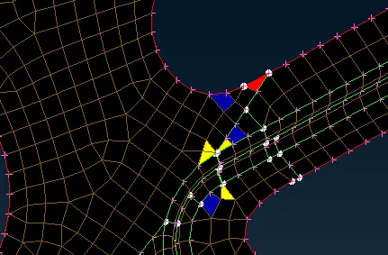
15. After generating the mesh for all the parts of the component now need to generate the same for the opposite symmetric part. we should not generate mesh for the parts which are not symmetry in the component.
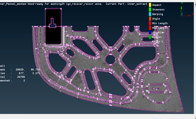
16.Now we have completed the mesh on the one side of the symmetric model for that we can generate the other symmetric side using transform tool
select transform tool > copy >select entities ( we need to select the elements to be generated on the symmetric side )> now we need to select the symmetry method as mirror 3 point plane > now select any three point on the mid plane.
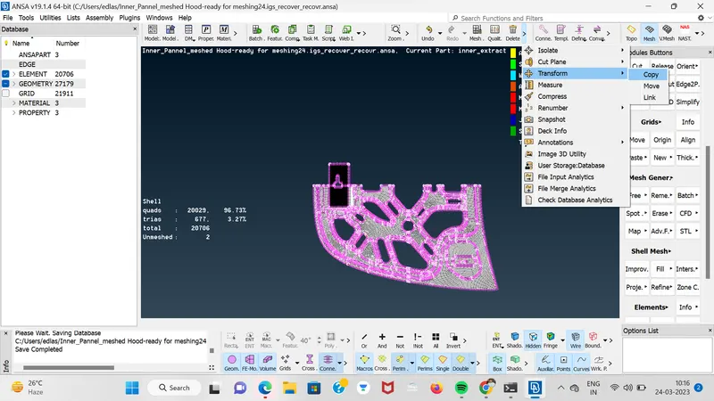
17. As the result the other part which is symmetry to the meshed component is generated shown below. now we need to mesh the area which we left they are not symmetric are need to b meshed now.
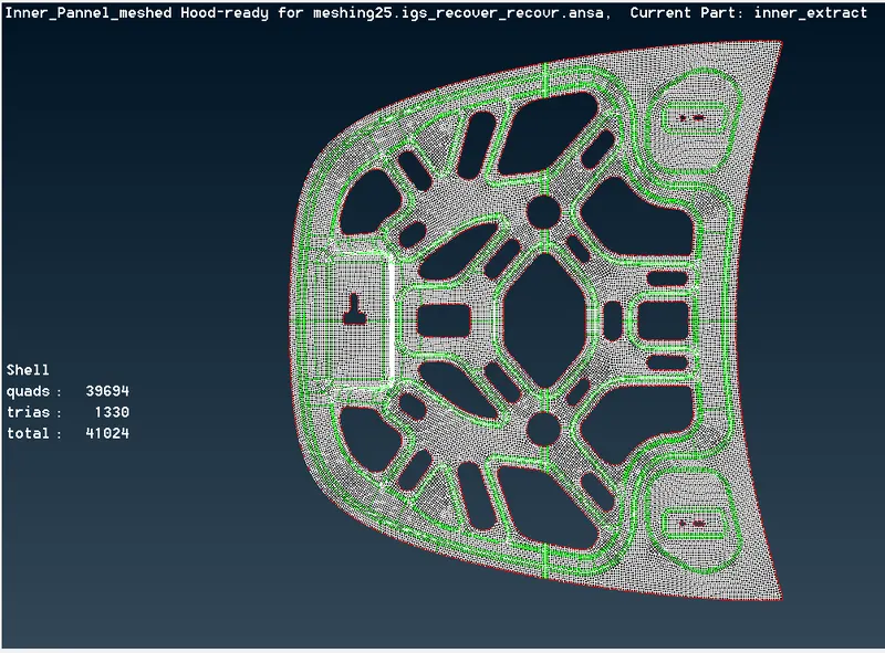 They 39694 numbers of quads and 1330 number of trais and 41024 total numbers of elements formed in the mesh.
learning out comes
- Learn how to fix geometry errors for the component.
- learn how to create new part for the generating mid surface
- learnt how extract mid surface for the component
- learnt how to fix the element distance which are failing the quality criteria.
- learnt who to mesh the complicated area
- learnt how to errors in the elements that is failing to the quality criteria
- learnt how to use some important tools like transform, scale, split, number+/_, smooth etc
conclusion
The given hood part meshed as per required quality criteria, after having carried out topology clean-up and generated midsurfaces for each of its components.