Week 3 - 2D meshing for sheet metal
Question:
For the given Hood model, Take the mid surface for all the components after checking the geometrical errors and mesh the mid surface with the given element Quality criteria. (Refer the table Below for the Quality criteria)
|
S.No |
Quality Criteria |
Value |
|
1 |
Target/Average length |
5 |
|
2 |
Minimum Length |
2 |
|
3 |
Maximum Length |
7 |
|
4 |
Aspect |
3 |
|
5 |
Warpage |
15 |
|
6 |
Skewness |
45 |
|
7 |
Jacobian |
0.7 |
|
8 |
Minimum Quad Angle |
45 |
|
9 |
Maximum Quad Angle |
135 |
|
10 |
Minimum Tria Angle |
30 |
|
11 |
Maximum Tria Angle |
120 |
|
10 |
Tria Percentage |
15 |
Solution:
Introduction:
Engine Hood:
The hood which is also known as ENCON, serves as an access panel to engine compartment of an automobile. It is an assembly made of Outer an Inner panels to meet various safety and design requirements.
The following are the design considerations involved in the design of Engine Hood.
- Pedestrian safety.
- Vehicle quality.
- Occupant safety.
- Styling.
- Manufacturability.
Types of Hoods:
- Invalid hood or Build N.
- Wrap around hood.
- Hood with fenders.
- Hood with border diagonal frames.
- Hood with brace frames.
Meshing of hood:
Here we will see the meshing of different parts of hood.
Hood consists of four different components as given below.
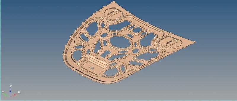
Fig01: Inner extract.
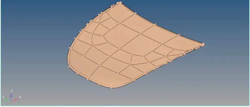
Fig02: Outer extract.
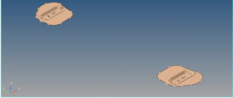
Fig03: Hinge.
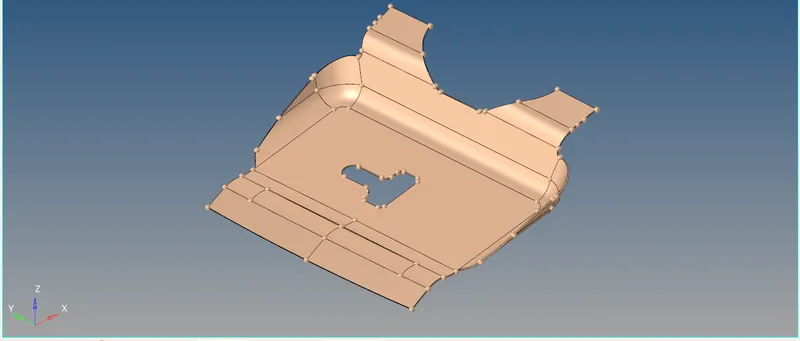
Fig04: Latch.
Now we will look at meshing of these components one by one.
Quality Criteria:
Quality criteria for the meshing of all the components are given as follows:
- Target Element Length: 5 Units.
| Sr. No. | Quality Criteria | Value |
| 1 | Target/Average length | 5 |
| 2 | Minimum length | 2 |
| 3 | Maximum length | 7 |
| 4 | Aspect ratio | 3 |
| 5 | Warpage | 15 |
| 6 | Skewness | 45 |
| 7 | Jacobian | 0.7 |
| 8 | Miniimum Quad Angle | 45 |
| 9 | Maximum Quad Angle | 135 |
| 10 | Minimum Tria Angle | 30 |
| 11 | Maximum Tria Angle | 120 |
| 12 | Tria Percentage | 15 |
01.
Meshing Inner Panel:
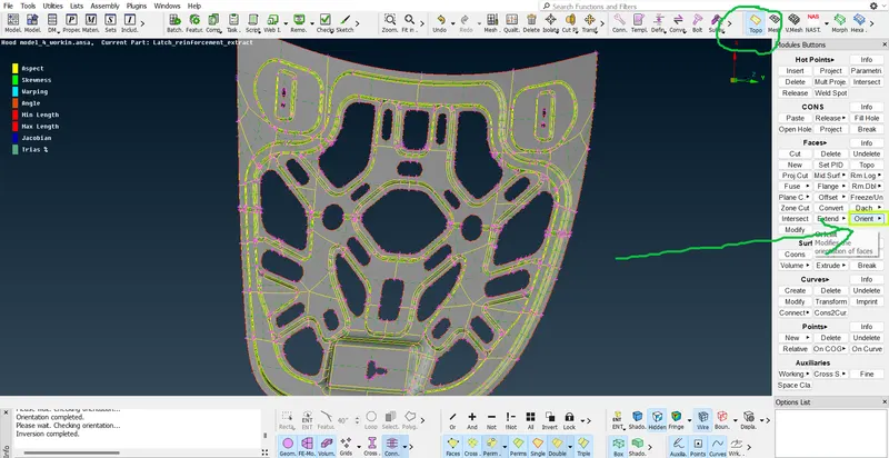
Fig1.1: Performing "Orientation" operation on the inner panel.
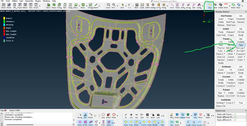
Fig1.2: Performing "Topo" operation on the inner panel.
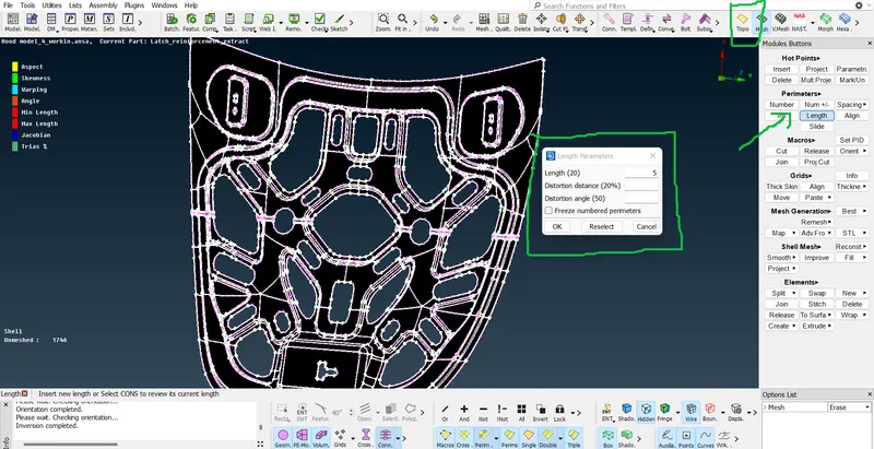
Fig1.3: Performing "Length (Perimeter and Micros)" operation on the inner panel.
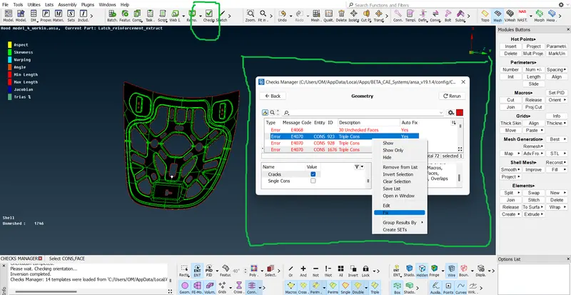
Fig1.4: Performing "Geometry check" operation on the inner panel.
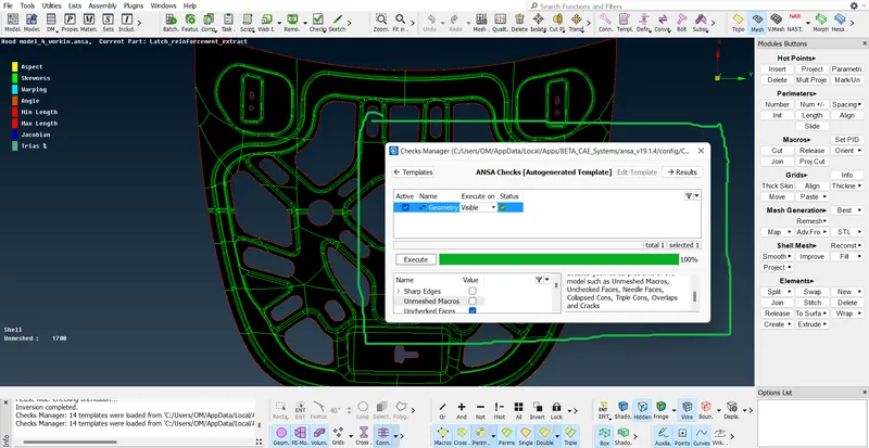
Fig1.5: Geometry without errors after performing "Geometry check" operation on the inner panel.
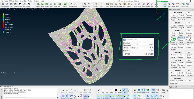
Fig1.6: Extracting Mid surface of inner panel by performing "Mid surface (skin)" operation.
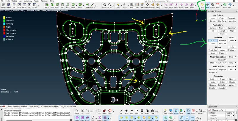
Fig1.7: Cleaning the mid surface of the inner panel by using "Join" operation.
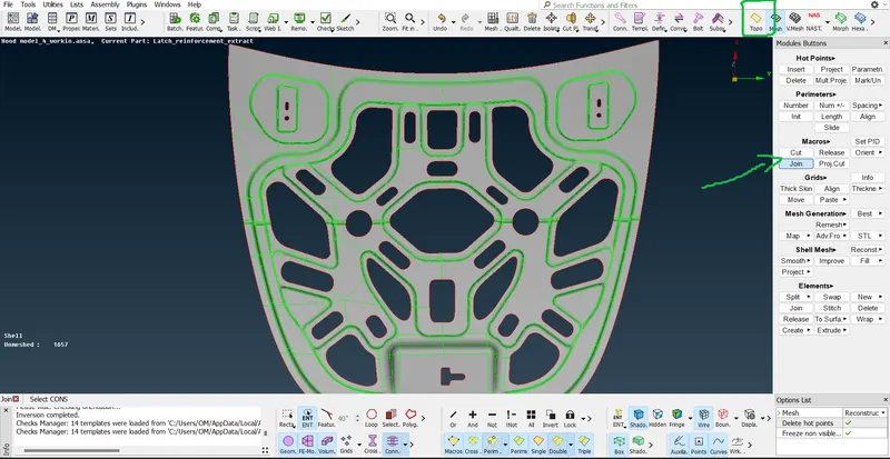
Fig1.8: Cleaned Mid surface of the inner panel after performing "Join" operation to clean up the surfaces.
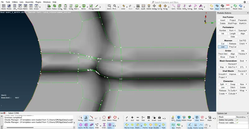
Fig1.9: Cleaning the critical areas like surface fillets of the inner panel by using "Join" operation.
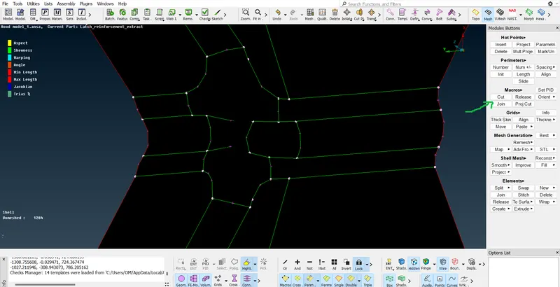
Fig1.10: Cleaned critical areas like surface fillets of the inner panel by using "Join" operation.
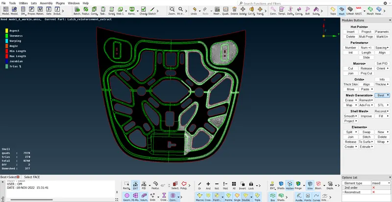
Fig1.11: Meshing the critical areas like surface fillets first followed by meshing of flat surfaces by using "Best" mesh option.
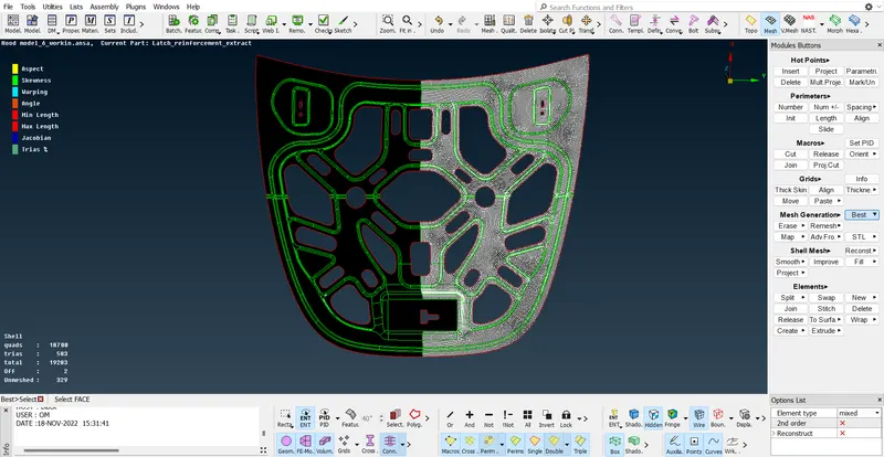
Fig1.12: Meshing the symmetric one half by using "Best" mesh option.
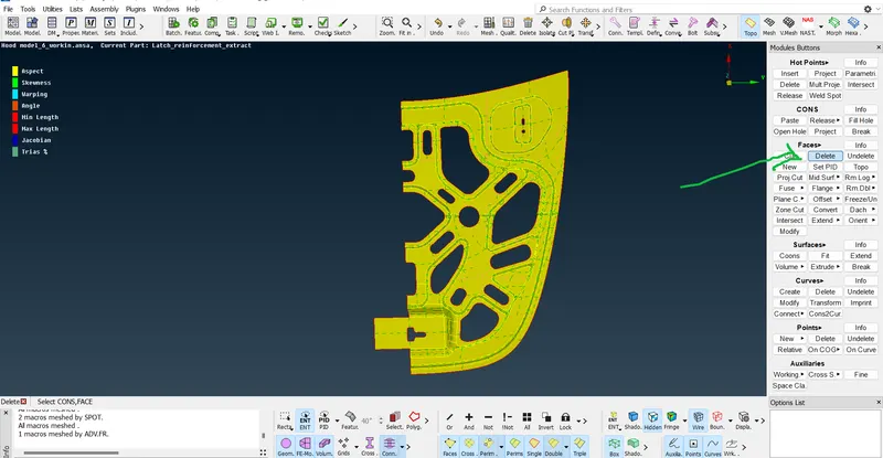
Fig1.13: Deleting the symmetric other half by using "Delete (faces)" option.
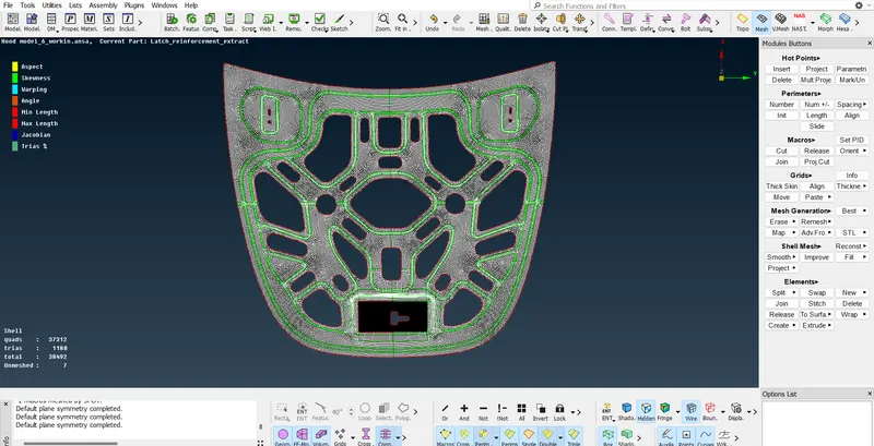
Fig1.14: Reflecting the symmetric surfaces and elements on other half by using "Transform (copy)" option.
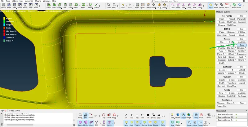
Fig1.15: Performing the "topo" operation to join the mirrored symmetric surfaces with the unsymmetric surfaces.
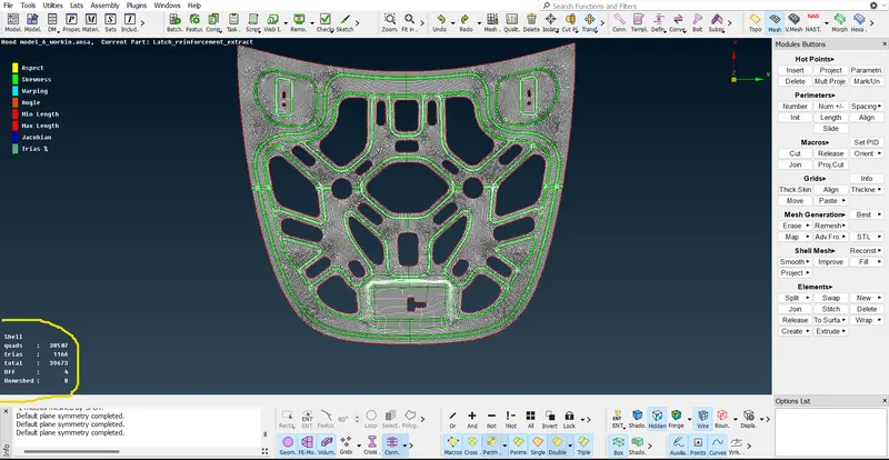
Fig1.16: Meshing the unsymmetric surfaces and checking for failed elements and unmeshed surfaces in the status bar.
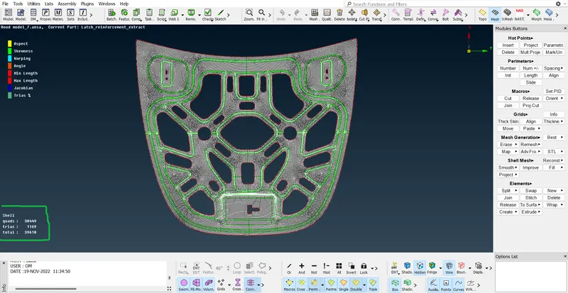
Fig1.17: Recontructing mesh and eliminating the failed elements to obtain the optimized quality of mesh.
02.
Meshing Outer Panel:
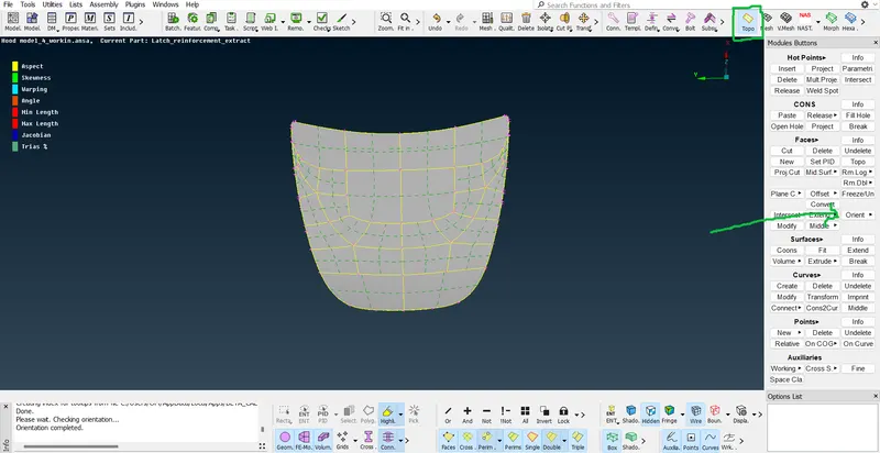
Fig2.1: Performing "Orientation" operation on the outer panel.
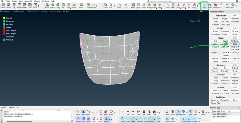
Fig2.2: Performing "Topo" operation on the outer panel.
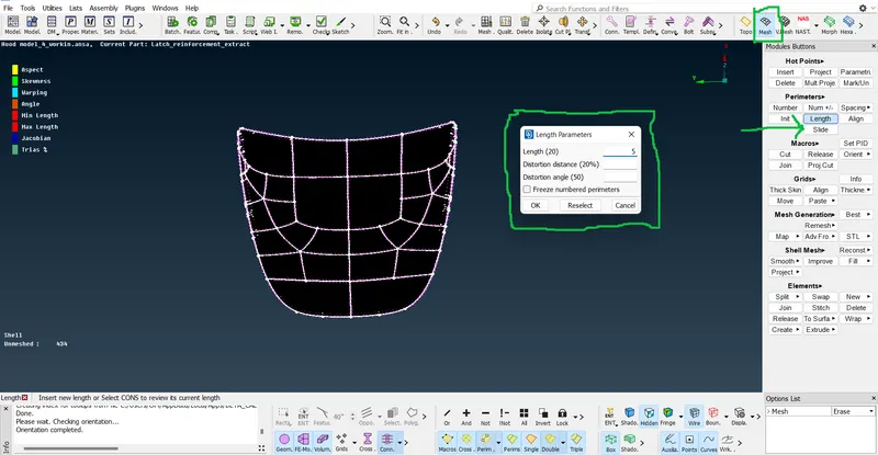
Fig2.3: Performing "Length (Perimeter and Micros)" operation on the outer panel.
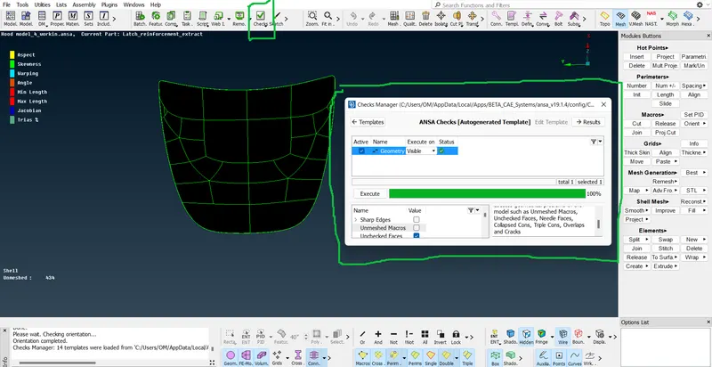
Fig2.4: Performing "Geometry check" operation on the outer panel.
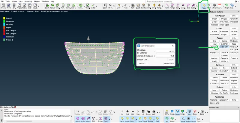
Fig2.5: Extracting Mid surface of outer panel by performing "Mid surface (skin)" operation.
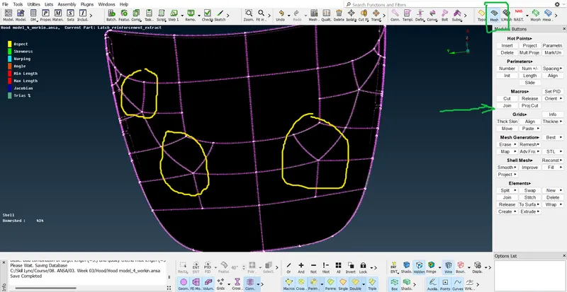
Fig2.6: Cleaning the mid surface of the outer panel by using "Join" operation.
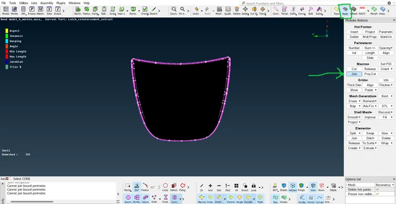
Fig2.7: Cleaned Mid surface of the outer panel after performing "Join" operation to clean up the surfaces.
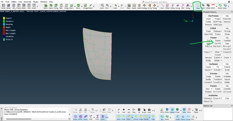
Fig2.8: Deleting the symmetric other half by using "Delete (faces)" option.
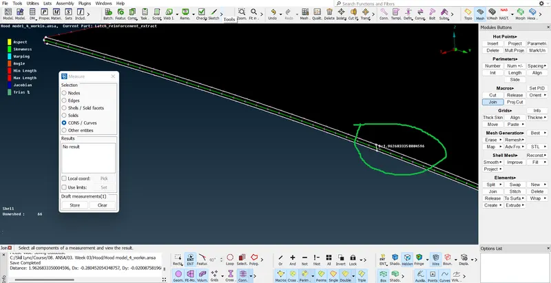
Fig2.9: Identifying the critical areas which can fail for minimum element length.
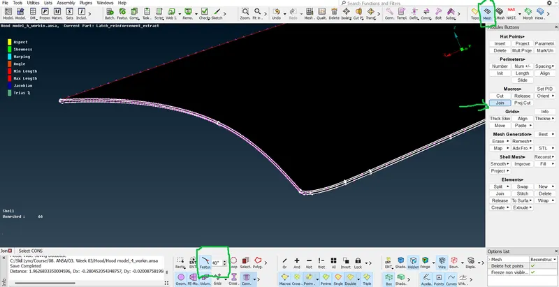
Fig2.10: Cleaning the critical areas like surface fillets of the outer panel by using "Join" operation.
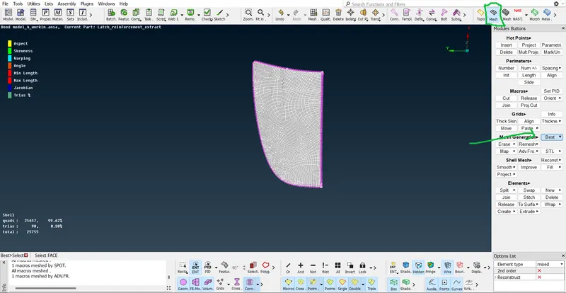
Fig2.11: Meshing the symmetric one half by using "Best" mesh option.
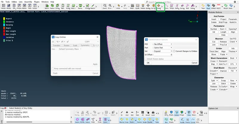
Fig2.12: Reflecting the symmetric surfaces and elements on other half by using "Transform (copy)" option.
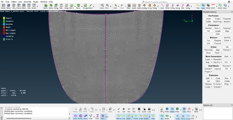
Fig2.13: Recontructing mesh and eliminating the failed elements to obtain the optimized quality of mesh.
03.
Meshing LH-RH Hinge reinforcements:
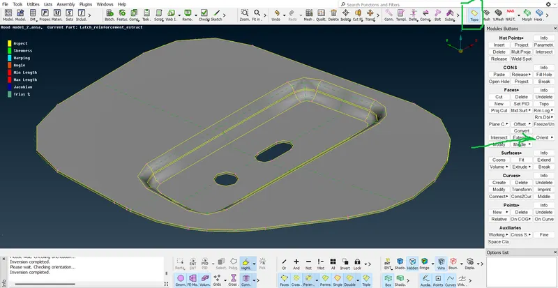
Fig3.1: Performing "Orientation" operation on the hinge reinforcement.
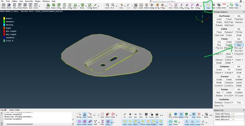
Fig3.2: Performing "Topo" operation on the hinge rreinforcement.
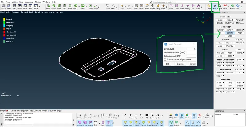
Fig3.3: Performing "Length (Perimeter and Micros)" operation on the hinge reinforcement.
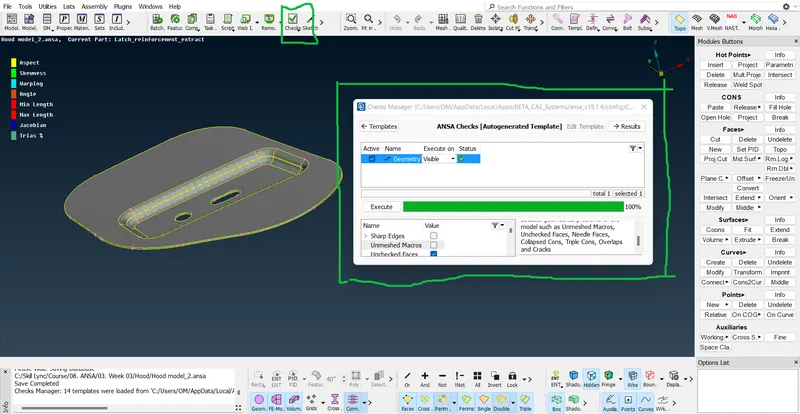
Fig3.4: Performing "Geometry check" operation on the hinge reinforcement.
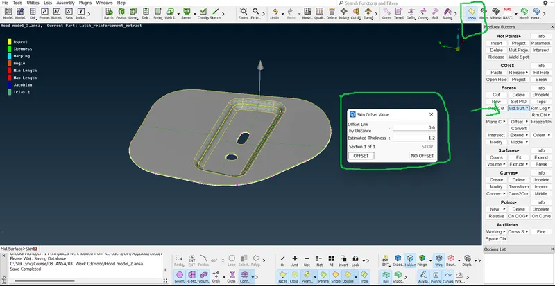
Fig3.5: Extracting Mid surface of outer panel by performing "Mid surface (skin)" operation.
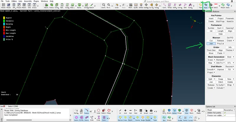
Fig3.6: Cleaning the critical areas like surface fillets of the outer panel by using "Join" operation.
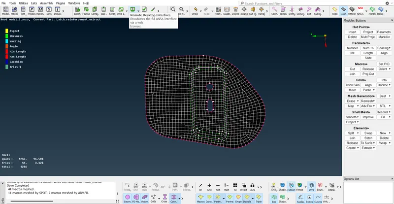
Fig3.7: Recontructing mesh and eliminating the failed elements to obtain the optimized quality of mesh.
04.
Meshing Latch-Striker reinforcement:
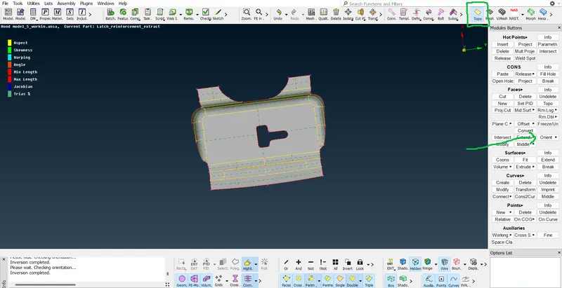
Fig4.1: Performing "Orientation" operation on the Latch-Striker reinforcement.
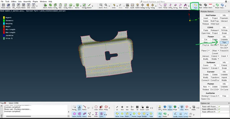
Fig4.2: Performing "Topo" operation on the Latch-Striker reinforcement.
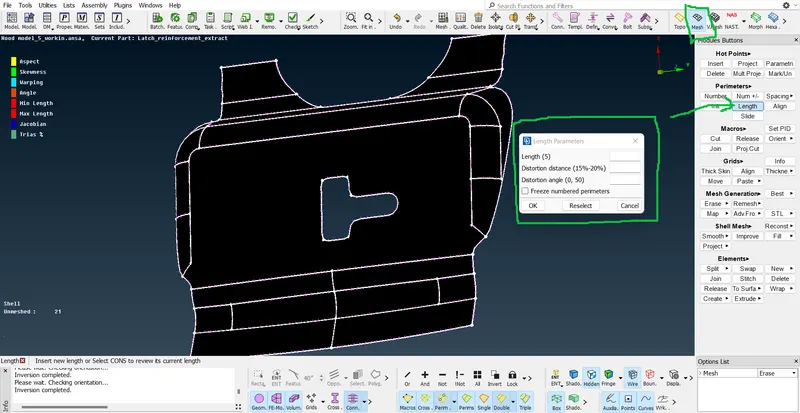
Fig4.3: Performing "Length (Perimeter and Micros)" operation on the Latch-Striker reinforcement.
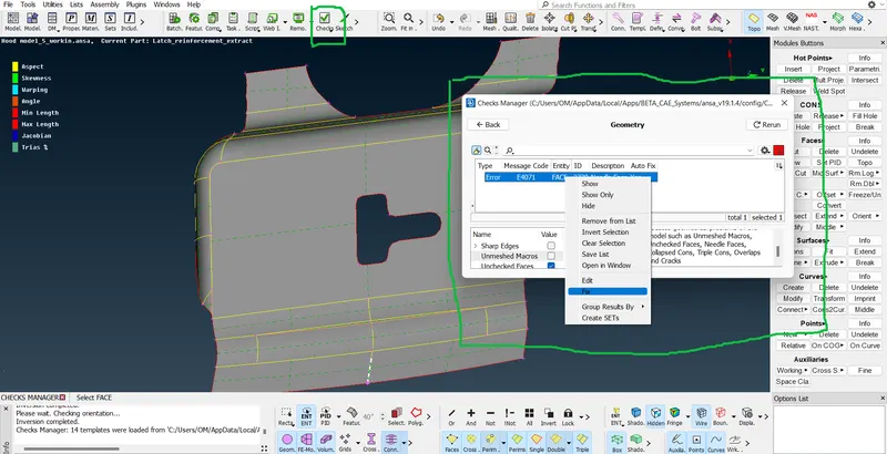
Fig4.4: Performing "Geometry check" operation on the Latch-Striker reinforcement.
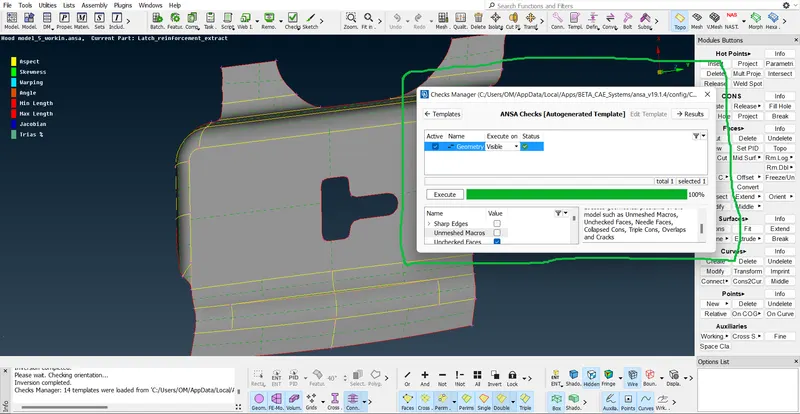
Fig4.5: Fixing the the issues with the Mid surface of Latch-Striker reinforcement.
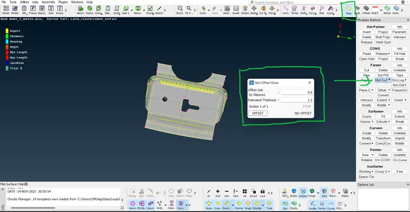
Fig4.6: Extracting Mid surface of Latch-Striker reinforcement by performing "Mid surface (skin)" operation.
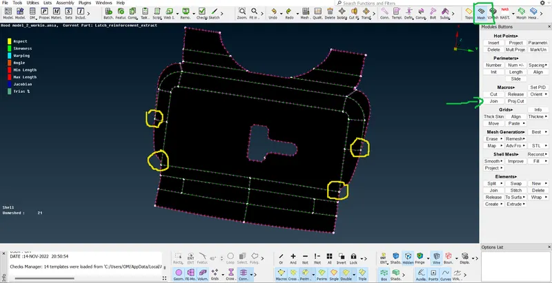
Fig4.7: Identifying the critical areas which can fail for minimum element length.
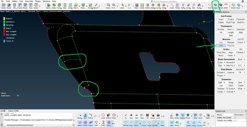
Fig4.8: Cleaning the critical areas like surface fillets of the Latch-Striker reinforcement by using "Join" operation.
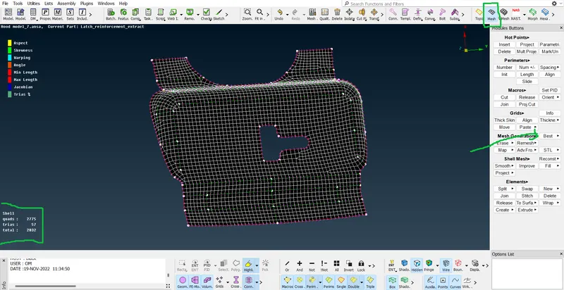
Fig4.9: Recontructing mesh and eliminating the failed elements to obtain the optimized quality of mesh.
Learning outcomes:
- We learnt and practiced, How to create mid surface for sheet metal components.
- To obtain the good mesh flow for sheet metal components with minimum number of elements failing for quality.
- To assign the thickness and othe properties to the extracted mid surface of the component.
Conclusion:
We studied and practiced the meshing of automotive hood with proper mesh flow, as per the quality requirements of the automotive sheet metal components.