Week 3 - 2D meshing for sheet metal
AIM
To extract the mid surface and then mesh the component with given quality parameters and assign the thickness on a hood component.
OBJECTIVE
Hood component is given with five different parts:
- Hatch.
- Left and right Hinge.
- Inner panel.
- Outer panel.
To assign the property on each part with their parent component thickness and then mesh the component with target size 5mm and as per given quality parameters.
| Sr. No | Quality Criteria | Value |
| 1 | Target/Average Length | 5 |
| 2 | Minimum Length | 2 |
| 3 | Maximum Length | 7 |
| 4 | Aspect | 3 |
| 5 | Warpage | 15 |
| 6 | Skewness | 45 |
| 7 | Jacobian | 0.7 |
| 8 | Minimum quad angle | 45 |
| 9 | Maximum quad angle | 135 |
| 10 | Minimum angle tria | 30 |
| 11 | Maximum angle tria | 120 |
| 12 | Tria percentage | 15 |
PROCEDURE
The hood component geometry is open in the Ansa for Meshing, the file is open with STP format, The hood component has four different parts which are locked differently to see each part individually to extract the middle surface and mesh the component.
THE COMPONENT
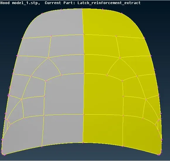
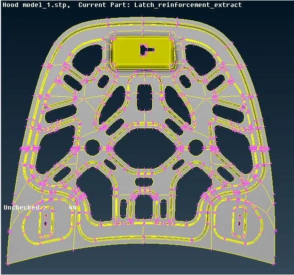
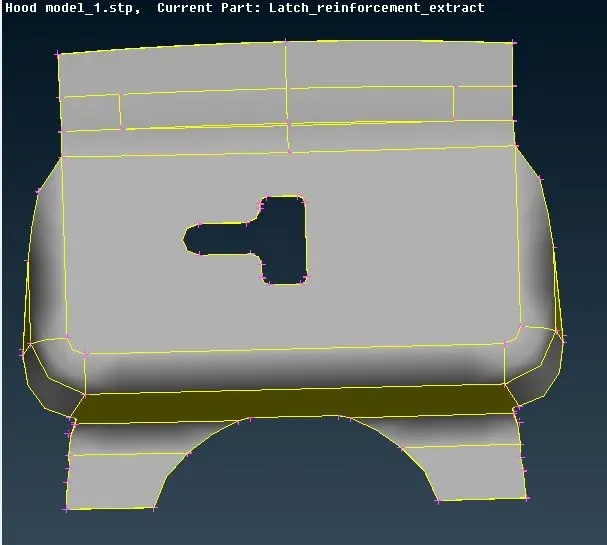
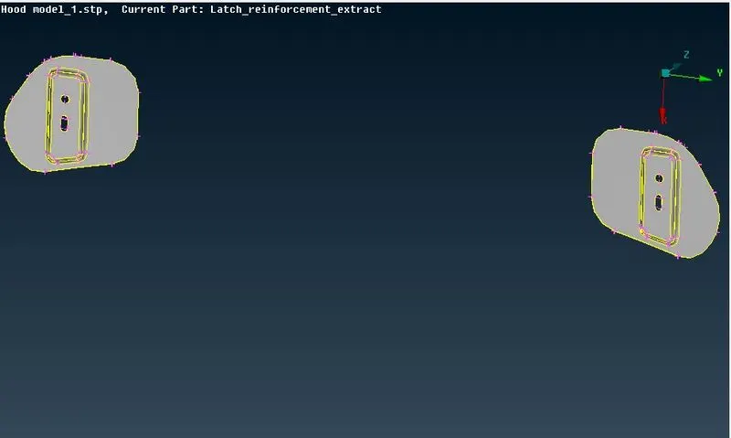
PROCEDURE
1. The part has 4 main components and they have different thicknesses (which are measured using the measure tool). They are as follows: Inner Panel - 0.75mm, Outer Panel - 0.75mm, Hinge Reinforcement - 1.2mm and Latch Reinforcement - 1.2mm.
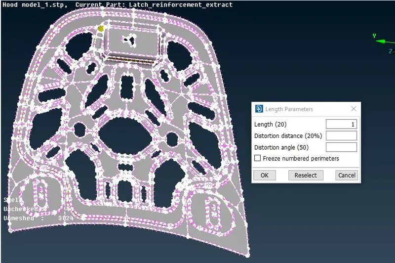
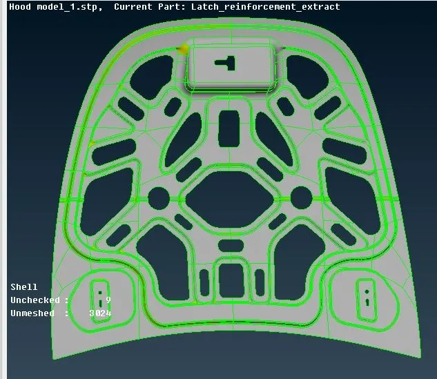
2. Initially, the part will not have proper resolution so to ensure proper detailing and viewing, we can use the length option which can be accessed through the Mesh module. This tool works in creating a finer representation of the model based on how finely the length of the feature lines is broken up into. All the surfaces need to be selected to use this tool.
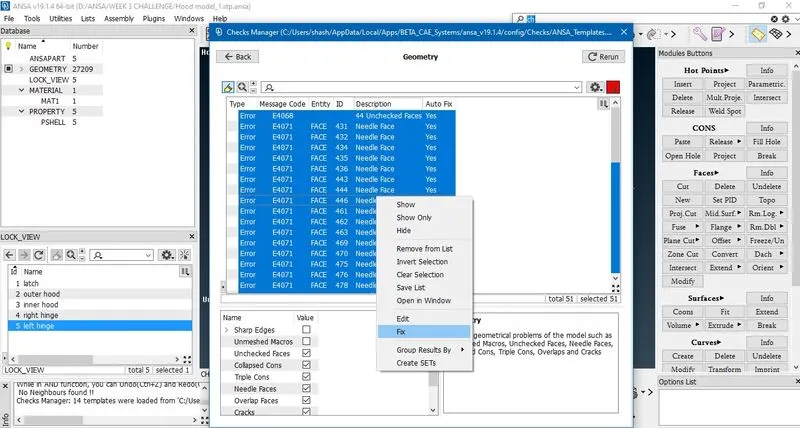
3. Before anything else is carried out, a geometry check and cleanup need to be carried out and ANSA has a tool that takes care of that. The checks tool can be accessed from the upper toolbar. Checks > Geometry. With all components visible, the checks can be 'executed'. The geometric discrepancies will be highlighted by the tool and they can all be selected, right clicked and fixed by clicking 'fix' as shown in the screenshot.
4. Now, we shall generate the midsurface of each surface. This can be done using the 'midsurface' tool in the faces menu or using the 'offset' tool from the Topo module. The midsurface tool would be ideal here as the components have a constant thickness. The offset tool would be more effective in cases of varying thicknesses. By using "skin offset" tool we can ensure that the mid surface is generated correctly and thickness is also assigned automatically using this tool. As it is a sheet metal component we can go with this tool.
The offset tool will show the direction of the offset in the form of an arrow. If it is in the opposite direction of the required offset, the offset value needs to be in negative, as shown in the screenshot. If we proceed, the surface will be offset and we will have the option of keeping the parent surfaces.
The midsurface tool also requires surface selection but you would need to select all the surfaces of the particular parent component. Furthermore, there will be an option to not delete the parent surfaces on the bottom right panel.
The offset can then be assigned their respective property, through the 'apply' option discussed in the previous step.
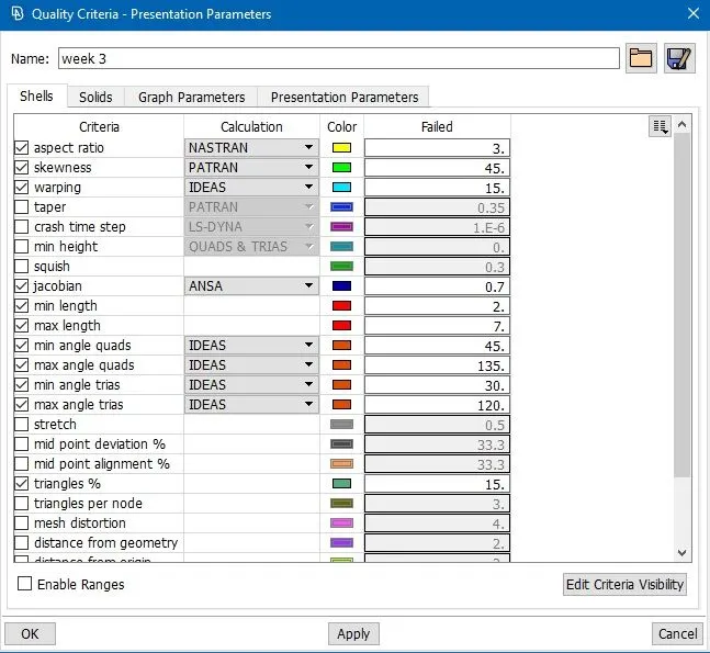
5. After midsurface is generated for each of the components, we can go ahead and prepare to mesh the midsurfaces. To start off, we can assign the quality parameters as per the challenge. We need to access the 'mesh parameters' and 'quality criteria' options from the top toolbar. And then we can assign the values as per the table. The mesh type will be 'mixed' and minimum and maximum lengths would be 2mm and 7mm respectively.
6. After that, we can go ahead and assign the target length. This is done by accessing the 'length' tool again from the Perimeters section under the Mesh module. We need to select the entire midsurface and assign the target length (which would be 5mm).
7. To facilitate better mesh flow and ensure good mesh quality, the midsurface needs further preparation with regards to proper surface cuts. This helps in prevention of tria formation.
Before we do that, we observe that some of the components can be separated into symmetric halves. To save on time, it's good practice to mesh half the component and reflect the mesh to generate the other half. So, we can go ahead and delete a half of the inner extract. The delete tool can be accessed from the top toolbar section.
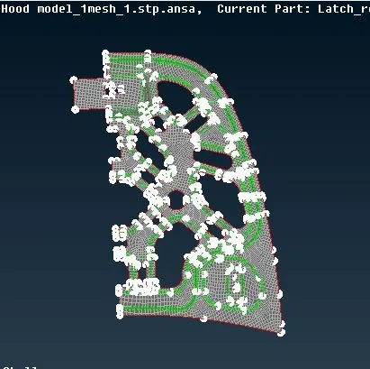
8. Cuts can be made using the 'Cut' tool from the Mesh module (under macros). We can go ahead and try our best to split up the surfaces to rectangular regions to ensure the least number of trias. Existing feature lines that may hinder this can also be suppressed. This is done by right-clicking the lines using the same 'cut' tool.
In other cases, this needs to be carried out to prevent minimum length failure. The most famous example of this in the hood component would be that of the hemming region of the outer extract panel. The feature lines on either side of the hemming peak need to be suppressed to prevent element failure.
9. After preparing the surfaces, we can go ahead and mesh them. We need to use the 'best' mesh option, which can be accessed from the 'Mesh Generation' section. It's good practice to start from an inner region of the component with free edges (single cons) and mesh the surrounding regions in an outward direction.
10. After meshing a region,we analyze the mesh and see if it can be improved. If it can be improved, we can make use of the 'Reconstruct' tool from the Shell Mesh section in the mesh module. It basically remeshes the selected mesh keeping the quality criteria in mind and tends to produce a better mesh. The tool gives the option to rerun the tool so we can ensure the produced mesh is up to the standards we are looking for.
This process is repeated until we mesh the entire component.Mesh quality can be checked by switching to hidden mode. The option is available on the bottom toolbar.
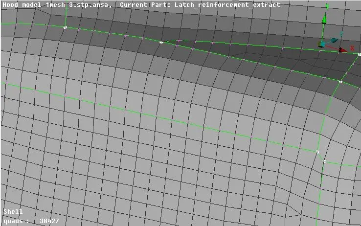
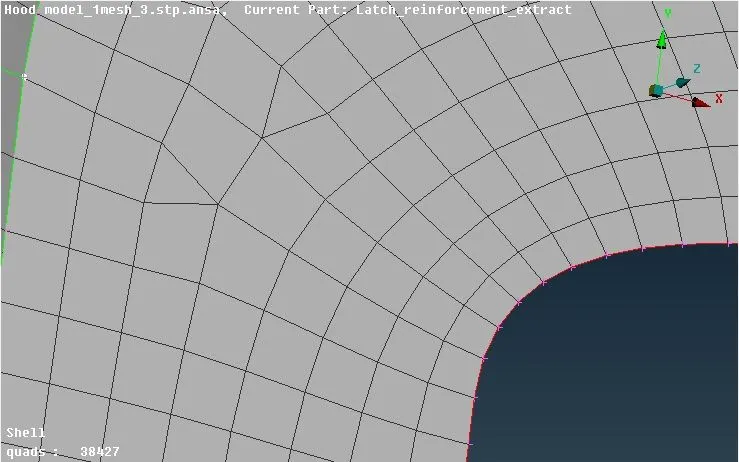
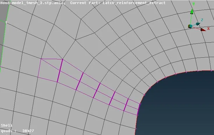
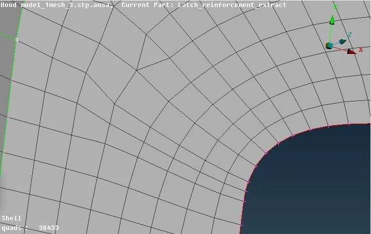
11. Sometimes, the reconstruct tool doesn't work in getting rid of some trias. Trias are okay but certain types of trias need to be avoided - like opposite trias or trias touching feature lines. Trias can be worked on using the swap, split, join and smooth tools. The first three are available in the 'Elements' section and the smooth tool is available in the 'Shell Mesh' section.
This process is repeated until we mesh the entire component.
Mesh quality can be checked by switching to hidden mode. The option is available on the bottom toolbar. The failing elements will be highlighted in the colours as per the legend on the side of the screen (of the quality criteria).
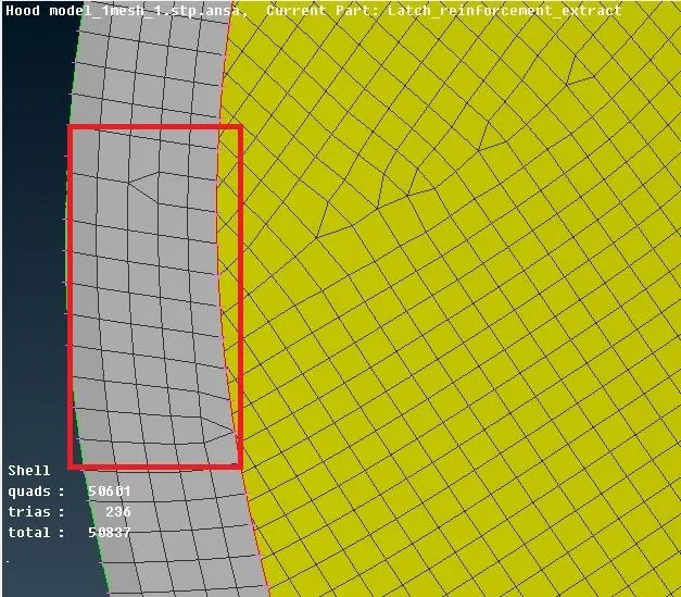
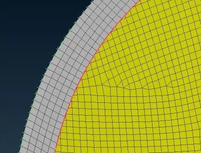
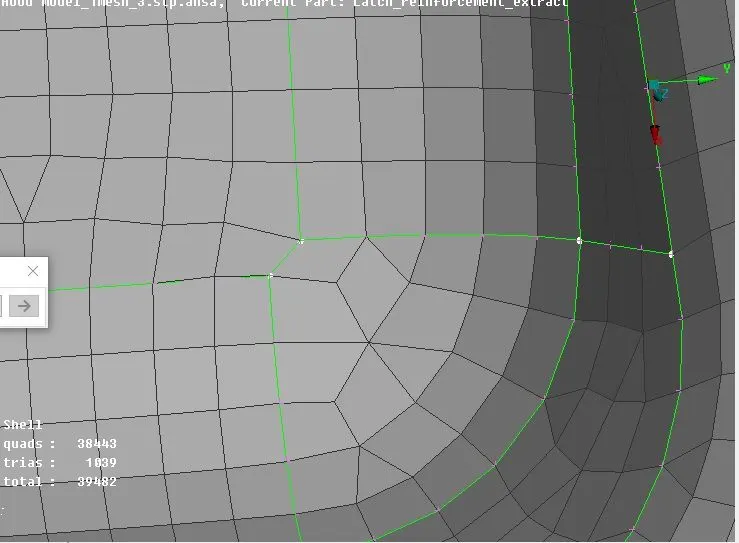
Below are some of the example, where mesh cleanup was done using the above mentioned tools.
[i] Opposite trias
[ii] Trias at construction lines
[iii] Tria removal using split elements and smooth command
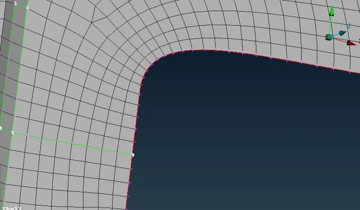
12. After all the regions to be meshed have been meshed, we can go ahead and work on transforming the component to produce the symmetrical region to complete the mesh for the entire component. This can be done by accessing the 'transform' tool from the top toolbar and selecting 'copy'. We can then select the entities that need to be symmetrically replicated. After that, we can move on to the next window and go to the symmetry tab and proceed without changing any of the options.
Some geometry checkups and fixing may be required based on the complexity of the component (through Checks > Geometry).
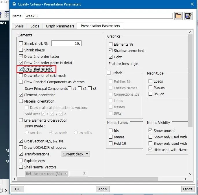
13. Finally, as required, draw shell as solid needs to be activated. This can be done by going to Quality Parameters and accessing the Presentation Parameters tab. In that section, the 'Draw Shell as Solid' box needs to be checked.
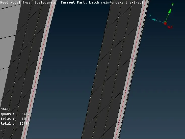
MESHED COMPONENT IMAGES
OUTER EXTRACT PANEL
INNER EXTRACT PANEL
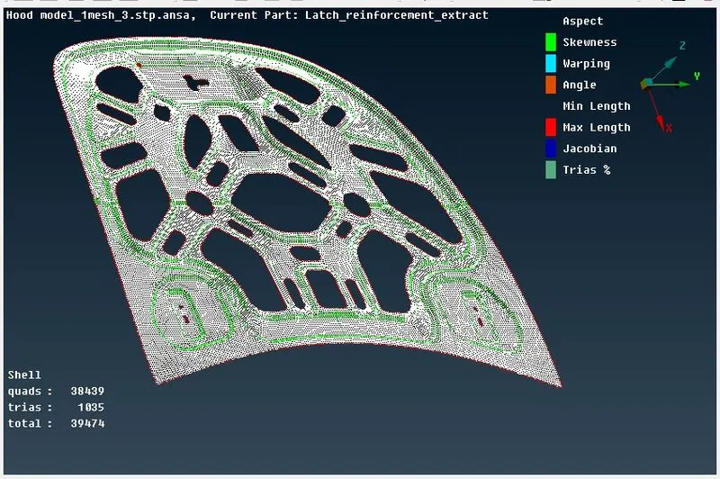
HINGE REINFORCEMENT
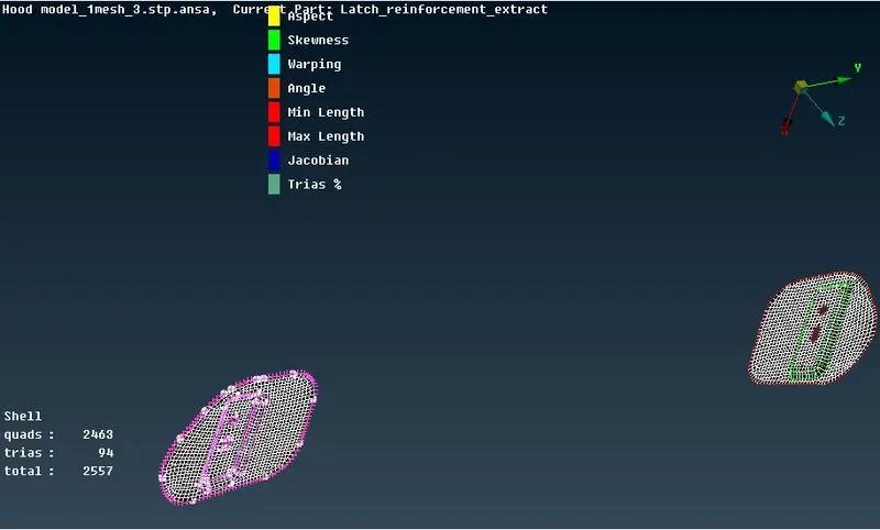
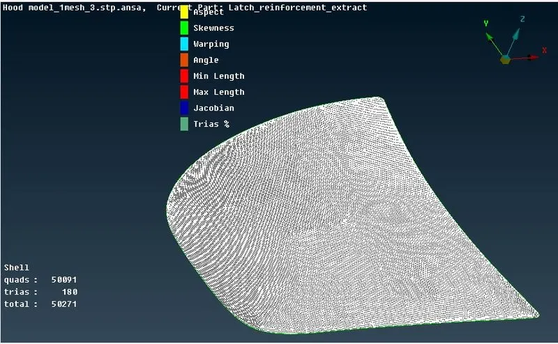
LATCH REINFORCEMENT
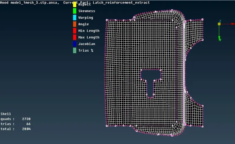
As seen, none of the components has OFF elements.
ALL MIDSURFACES ASSEMBLED:
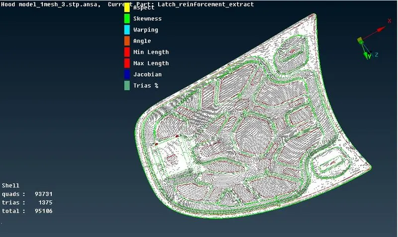
There are 1375 trias out of the total 95106, meaning the tria percentage is 1.44%.
LEARNING OUTCOMES
1. Application of several versatile tools that are part of the ANSA ensemble.
2. Understanding of the more automated geometry cleanup process and other geometric tools used to facilitate meshing process in the TOPO module.
3. Understanding of midsurface generation options available in ANSA.
4. Understanding of meshing techniques, property creation and application, quality criteria and mesh cleanup procedures.
CONCLUSION
The given hood part was meshed as per required quality criteria, after having carried out topology cleanup and generated midsurfaces for each of its components and thickness was assigned to each of them.