Week 3 - 2D meshing for sheet metal
For the given Hood model, Take the mid surface for all the components after checking the geometrical errors and mesh the mid surface with the given element Quality criteria. (Refer the table Below for the Quality criteria)
|
S.No |
Quality Criteria |
Value |
|
1 |
Target/Average length |
5 |
|
2 |
Minimum Length |
2 |
|
3 |
Maximum Length |
7 |
|
4 |
Aspect |
3 |
|
5 |
Warpage |
15 |
|
6 |
Skewness |
45 |
|
7 |
Jacobian |
0.7 |
|
8 |
Minimum Quad Angle |
45 |
|
9 |
Maximum Quad Angle |
135 |
|
10 |
Minimum Tria Angle |
30 |
|
11 |
Maximum Tria Angle |
120 |
|
10 |
Tria Percentage |
15 |
ANSWER -:
OBJECTIVE -:
To mesh the given hood component after proper geometry cleanup and midsurface generation using the ANSA preprocessing software. Also, to ensure the generated mesh follows the given quality criteria and the corresponding thickness of each surface is assigned to the mesh.
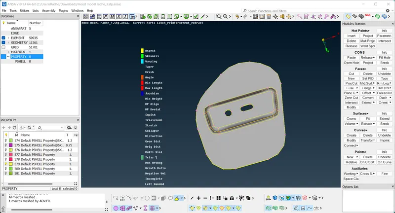
Hinge Midsurface -:
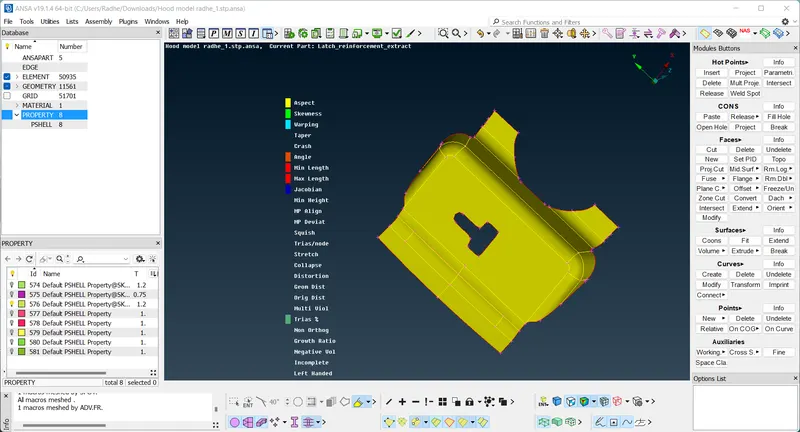
Latch Midsurface -:
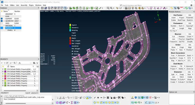
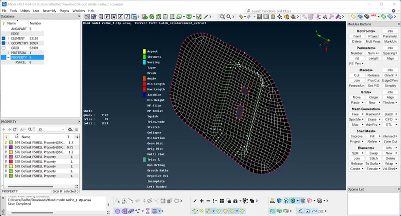
MESH COMPONENT -:
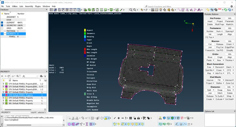
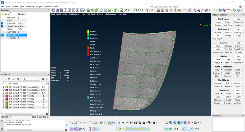
PROCEDURE -:
1. The part has 4 main components and they have different thicknesses (which are measured using the measure tool). They are as follows: Inner Panel - 0.75mm, Outer Panel - 0.75mm, Hinge Reinforcement - 1.2mm and Latch Reinforcement - 1.2mm.
2. Initially, the part will not have proper resolution so to ensure proper detailing and viewing, we can use the length option which can be accessed through the Mesh module. This tool works in creating a finer representation of the model based on how finely the length of the feature lines is broken up into. All the surfaces need to be selected to use this tool.
3. Before anything else is carried out, a geometry check and cleanup need to be carried out and ANSA has a tool that takes care of that. The checks tool can be accessed from the upper toolbar. Checks > Geometry. With all components visible, the checks can be 'executed'. The geometric discrepancies will be highlighted by the tool and they can all be selected, right clicked and fixed by clicking 'fix' as shown in the screenshot.
4. Before anything else is carried out, a geometry check and cleanup need to be carried out and ANSA has a tool that takes care of that. The checks tool can be accessed from the upper toolbar. Checks > Geometry. With all components visible, the checks can be 'executed'. The geometric discrepancies will be highlighted by the tool and they can all be selected, right clicked and fixed by clicking 'fix' as shown in the screenshot.
5. Now, we shall generate the midsurface of each surface. This can be done using the 'midsurface' tool in the faces menu or using the 'offset' tool from the Topo module. The midsurface tool would be ideal here as the components have a constant thickness. The offset tool would be more effective in cases of varying thicknesses. For practice purposes, I went with the offset tool.
After selecting the offset tool, it will ask us to select the surfaces to offset. We can select the surfaces on one side of the component. After that, we can assign the offset value (half the thickness).
The offset tool will show the direction of the offset in the form of an arrow. If it is in the opposite direction of the required offset, the offset value needs to be in negative, as shown in the screenshot. If we proceed, the surface will be offset and we will have the option of keeping the parent surfaces.
The midsurface tool also requires surface selection but you would need to select all the surfaces of the particular parent component. Furthermore, there will be an option to not delete the parent surfaces on the bottom right panel.
The offset can then be assigned their respective property, through the 'apply' option discussed in the previous step.
6. After midsurface is generated for each of the components, we can go ahead and prepare to mesh the midsurfaces. To start off, we can assign the quality parameters as per the challenge. We need to access the 'mesh parameters' and 'quality criteria' options from the top toolbar. And then we can assign the values as per the table. The mesh type will be 'mixed' and minimum and maximum lengths would be 2mm and 7mm respectively.
7. After preparing the surfaces, we can go ahead and mesh them. We need to use the 'best' mesh option, which can be accessed from the 'Mesh Generation' section. It's good practice to start from an inner region of the component with free edges (single cons) and mesh the surrounding regions in an outward direction.
8. After meshing a region, analyze the mesh and see if it can be improved. If it can be improved, we can make use of the 'Reconstruct' tool from the Shell Mesh section in the mesh module. It basically remeshes the selected mesh keeping the quality criteria in mind and tends to produce a better mesh. The tool gives the option to rerun the tool so we can ensure the produced mesh is up to the standards we are looking for.
LEARNING OUTCOMES
1. Application of several versatile tools that are part of the ANSA ensemble.
2. Understanding of the more automated geometry cleanup process and other geometric tools used to facilitate meshing process in the TOPO module.
3. Understanding of midsurface generation options available in ANSA.
4. Understanding of meshing techniques, property creation and application, quality criteria and mesh cleanup procedures.
CONCLUSION
The given hood part was meshed as per required quality criteria, after having carried out topology cleanup and generated midsurfaces for each of its components and thickness was assigned to each of them.