Week 3 - 2D meshing for sheet metal
#10. Week 3 // 2D meshing for sheet metal.
AIM: 2D Meshing for sheet metal (car hood).
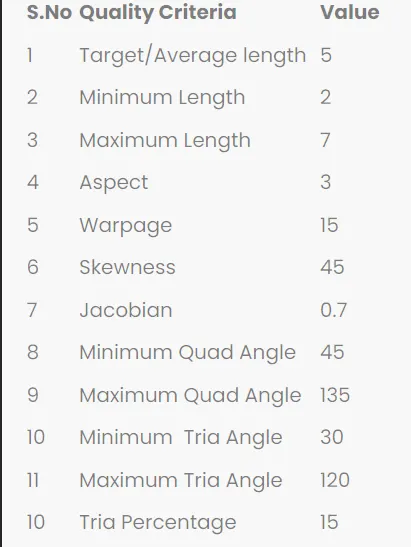
OBJECTIVE: For the given Hood model, we have to perform pre-processing i.e., Geometry clean-up, Mid surface extraction, and 2D shell meshing for the hood component of a car. After meshing, component thickness and material need to be assigned to the mesh. And the mesh should follow the given element quality criteria,
INTRODUCTION:
COMPUTER AIDED ENGINEERING (CAE)-
Computer-aided engineering (CAE) is the use of computer software to simulate performance in order to improve product designs or assist in the resolution of engineering problems for a wide range of industries. This includes simulation, validation and optimization of products, processes and manufacturing tools.
A typical CAE process comprises of Pre-processing, Solving and Post-processing steps. In the pre-processing phase, engineers model the geometry (or a system representation) and the physical properties of the design, as well as the environment in the form of applied loads or constraints. Next, the model is solved using an appropriate mathematical formulation of the underlying physics. In the post-processing phase, the results are presented to the engineer for review.
Automatic Net Generation for Structural Analysis (ANSA):-
ANSA - Stands for Automatic net generation for structural analysis. ANSA is an advanced multidisciplinary CAE pre-processing tool that provides all the necessary functionality for full-model build up, from CAD data to ready-to-run solver input file, in a single integrated environment.
ANSA is the users’ preference due to its wide range of features and tools that meet their needs. The list of productive and versatile features is long and the alternative tasks and processes to be completed using them are countless.
HOODS ( car )-
The hood or bonnet is the hinged cover over the engine of motor vehicles. Hoods can open to allow access to the engine compartment, or trunk on rear-engine and some mid-engine vehicles for maintenance and repair.
On front-engine cars, the hood may be hinged at either the front or the rear edge, or in earlier models (e.g., the Ford Model T) it may be split into two sections, one on each side, each hinged along the centreline. A further variant combines the bonnet and wheel arches into one section and allows the entire front bodywork to tilt forwards around a pivot near the front of the vehicle.
Hoods are usually made from the same material as the rest of the body. This can be steel, aluminium, fiberglass, or carbon fibre. However, some aftermarket companies produce fiberglass or carbon fibre steel hood replacements to make the vehicle lighter.
The hood release system is common on most vehicles and typically consists of an inner hood latch/lock handle, a hood release cable, and a hood lock assembly. The hood lock handle is usually located under the steering wheel, next to the driver’s seat, or in the door frame.
We have followed various steps in order to execute mesh for given component whose procedures are follows,
- Geometry Clean-up.
- Topology
- Midsurfacing of component
- Set PID
- Geometry check-up / Defeaturing
- Meshing
PROCEDURE :
short note--
- Open the hood model from the files and it must be carried out for several operations.
- Check the geometry of the model from the 'checks' and execute the operation by selecting required check parameters.
- Fix the geometry manually or by means of auto fix (geometry clean up).
We are providing with a hood containing 5 properties or components.
- After geometric clean up, we have to perform 'MID SURFACING' for each property.
- Mid surfacing can be done manually by offset method or automatically.
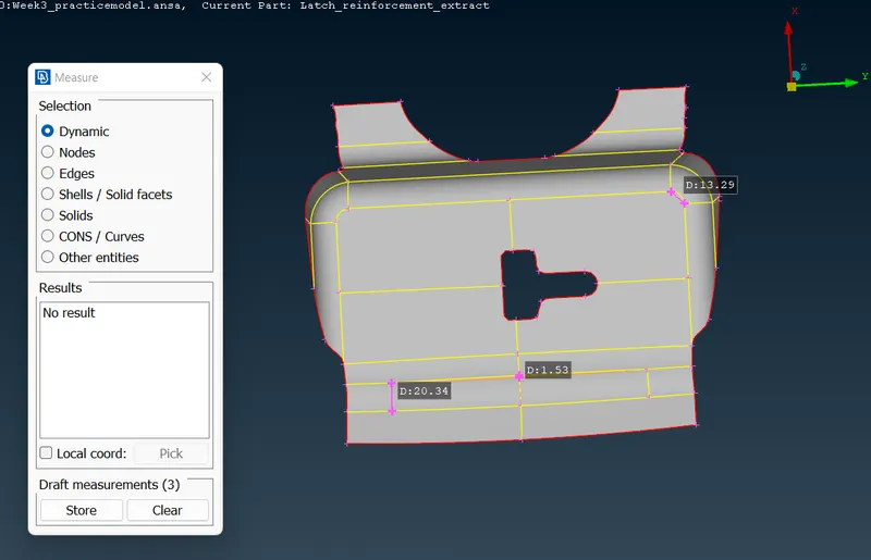
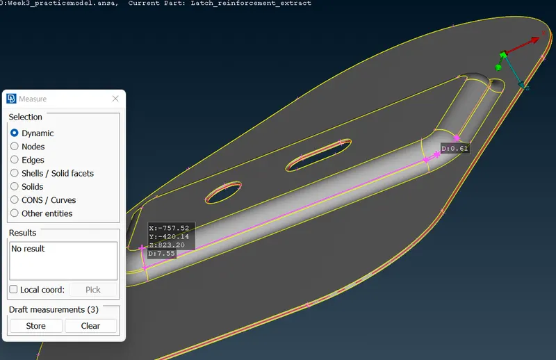
- Measure the thickness of the component by measure command.
[//From TOPO ----> Faces --> Offset (enabling the feature area ON in 40 degree) select any face of the model, ensure that the other face is not selected.
After selecting the face, we are supposed to provide the offset length (thickness/2) and sign regarding offset direction (+ or -).
The offsite surface needs to be extracted in order to perform meshing, for this
select ‘Not' (for hiding the selected entities) and turning ON 'PID’ then select the non mid surface and entering by middle clicking.
OR
select ‘!Not ' ( to keep only the selected entities ) and turning ON the 'PID' , then select the mid surface and enter .
The neighbouring surfaces can be founded by using " And ".
Otherwise, we use property (ctrl+p) for selecting various parts of the model.//]
First, the hood model is imported into the ANSA. The hood model contains five individual components as shown below,
1.OUTER PANEL-
2.INNER PANEL-
3. LATCH_REINFORCEMENT-
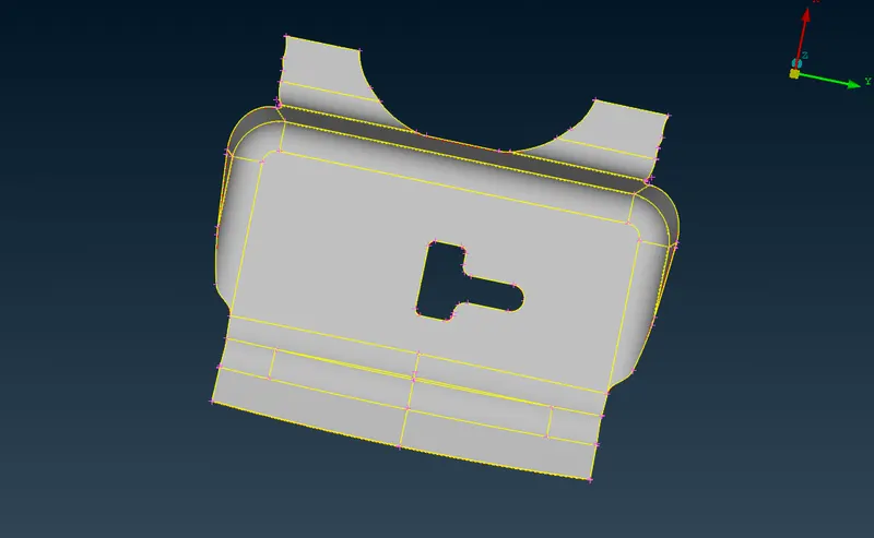
4.HINGE_REINFORCEMENT-
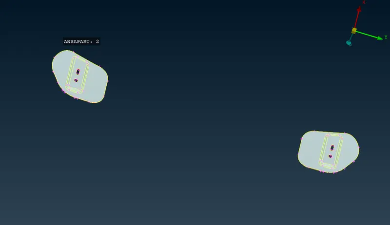
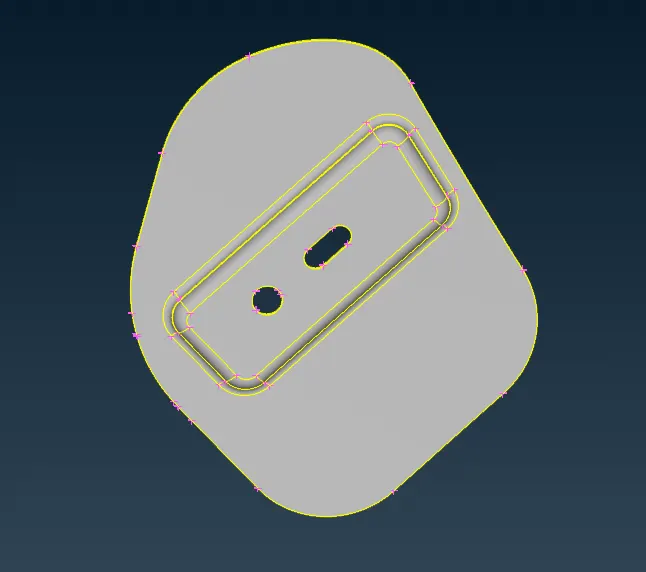
The first step after importing the model is to properly analyze and understand the geometry. When a CAD model is imported into the ANSA, there might be several geometrical errors like missing/distorted surfaces, intersecting surfaces, etc. due to the format conversion process or inherent bad model. And, it is important to clear all these errors before starting meshing. So, the next step is to clean up the geometry. To ensure that all the surfaces are connected properly Faces>Topo tool is used for all the edges of each individual component at a time. Next, geometry check is performed by going to Checks>Geometry and running it for parameters as shown in the image below. Another image shows the errors detected.
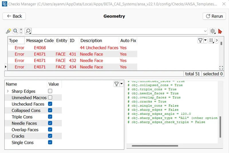
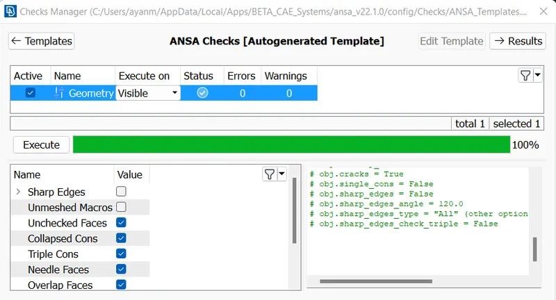
Most of the errors were fixed automatically by right-clicking on the error>fix. Next, the orientation of all the faces is modified by going to Faces>Orient. This ensures that all faces are oriented similarly.
The next, step is to extract the mid surfaces for each component and keep them in separate property id. Midsurfaces are extracted using the manual method i.e., offsetting the surfaces of either face to the middle. First, the thickness of each component is measured using the Measure tool from Utilities>Measure. The outer panel and inner panel were found to be 0.75mm thick and the latch and hinges were found to be 1.2mm. As they are sheet metal components, the thickness is uniform across the component. Then, four properties are created by going to List>Properties>New. Thickness is assigned to each property and a Material 'Steel' is also created and assigned to each property. The image below shows the created properties with Ids 1,2,3,&4.
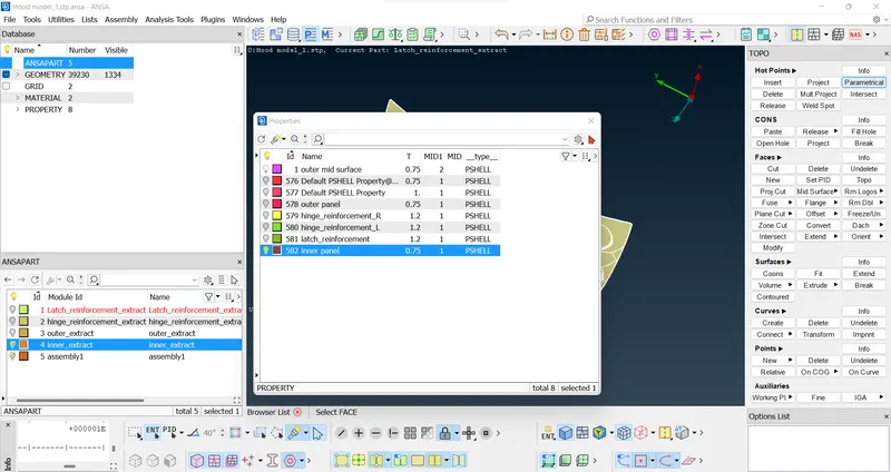
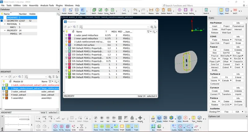
Next, the mid surface is extracted using the Offset tool by going to Faces>Offset and selecting all the surfaces on one face. Then, half of the thickness is given as the offset value, the direction is checked and offset. Now, the property is assigned to the extracted mid surface by going to Faces>Set PID and assigning to the respective property. Similarly, all mid surfaces are extracted and property assigned for all the components.
As the Outer panel and Inner panel (except one surface) are symmetrical, only half mid surface is extracted. Similarly, both hinges are mirror images of each other, so the mid surface is extracted for only one hinge.
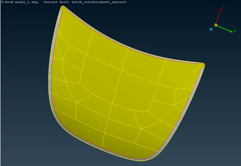
Again, the extracted mid surfaces are checked for geometric errors and fixed. The final extracted mid surfaces are shown below,
1.OUTER PANEL >MID-SURFACE:-
2.INNER PANEL >MID-SURFACE:-
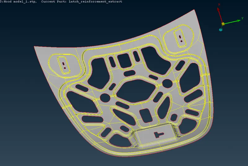
3. LATCH_REINFORCEMENT >MID-SURFACE:-
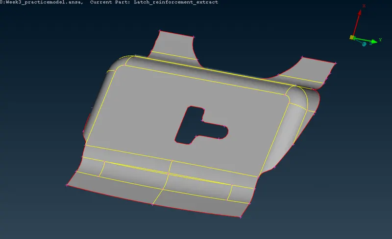
4.HINGE_REINFORCEMENT >MID-SURFACE:-
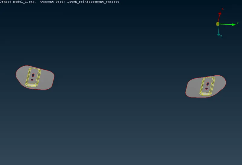
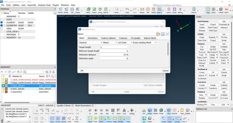
Next, mesh parameters are configured by going to Utilities>Mesh Parameters. There, target length =5, minimum element length =2, and maximum element length =7 is configured. All other parameters are kept as default for mixed and 1st order elements.
Then next, quality criteria are configured by going to Utilities>Quality Criteria. And, the quality criteria file is saved for future reference. The created quality criteria parameters are shown in the image below,
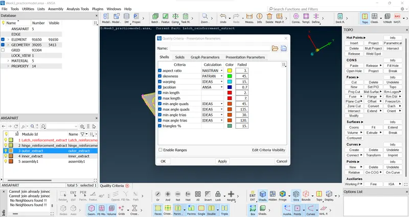
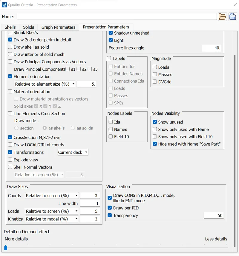
[Note- Go to presentation parameter and turn ON the elements %. & Deatil on Demand Effect in more detail.]
The next step is to prepare the mid surfaces for meshing. For that, switch to the Mesh module. First, the shell element length is altered by going to Perimeters>Length and all the CONS are selected and target element length 5 is fed as length value. The same is done for all the Macros (surfaces).
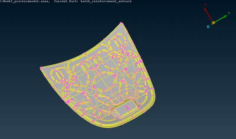
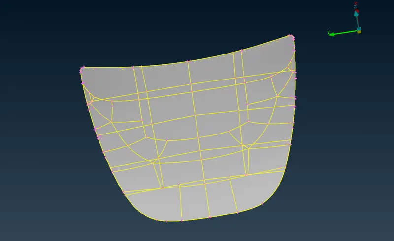
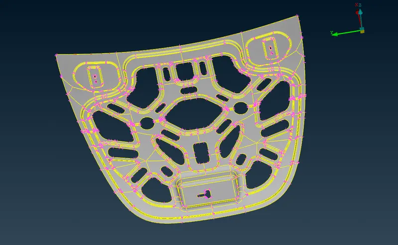
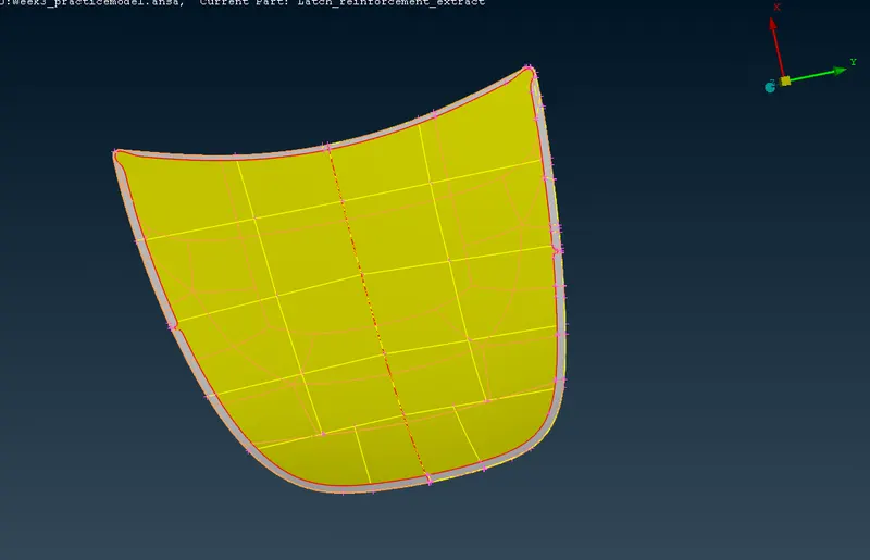
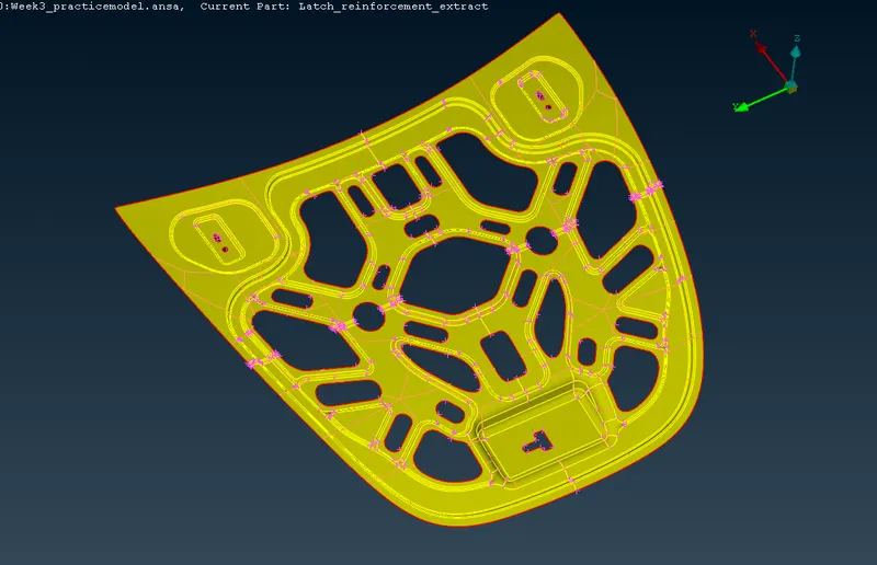
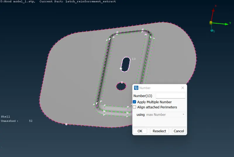
Next, all the areas are checked for minimum element length and altered where elements might fail for minimum length. Similarly, CONS which are not essential to define a feature are removed by joining the surfaces using the Macros>Join tool. Also, the complete mid surface model is divided strategically into sections using Macros>Cut and Macros>Project Cut tool. This will help to generate a better-quality mesh. Also, all the holes are rotated using the Perimeters>Slide tool to ensure the CONS are parallel to the nearby CON. This will help in generating a mesh with good flow. The result of the above steps is shown in the image below. The same process is repeated for all the mid surface components.
1.OUTER PANEL >MID-SURFACE >Geometry Check/Defeaturing:-
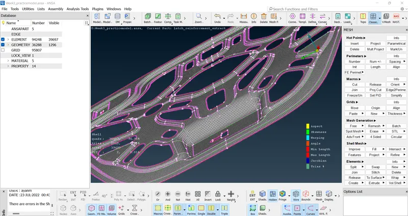
2.INNER PANEL >MID-SURFACE >Geometry Check/Defeaturing:-
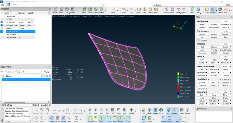
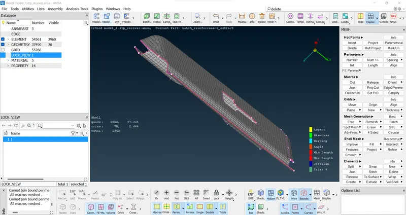
3. LATCH_REINFORCEMENT >MID-SURFACE >Geometry Check/Defeaturing:-
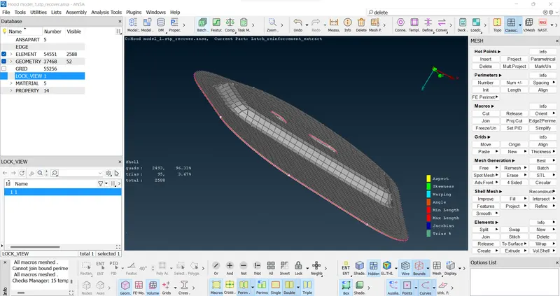
4.HINGE_REINFORCEMENT >MID-SURFACE >Geometry Check/Defeaturing:-
check for even number if not then put even number or use ' num+/- '.
Orange CON (edge) represents the joined macros (surfaces) and yellow CON is the new split done to divide the geometry into sections. Also, elements would fail for minimum length in the hemming region. So, for the hemming region, it is split into half along its length and the CON above and below are removed by joining the macros (surfaces) as shown above,
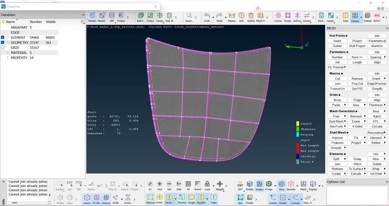
Next, meshing is done using the Mesh generation>Best tool. This tool generates the mesh using the best algorithm applicable. Then, the created mesh is refined using the Shell Mesh>Reconstruct tool. It is ensured that there are no rotating quads. Also, trias are kept as low as possible. While dealing with trias, the following things need to be ensured.
- No back-to-back trias touching each other
- No opposite trias
- No trias touching the edges
- No trias on a feature
- Low concentration of trias in a region
To deal with trias, the following tools are used,
- Grid>Paste, to paste the nodes and move tria backward
- Elements>Split, to split an element and move tria forward
- Elements>Swap, to move the tria left or right
- Elements>Join, to join two trias to make a quad
After modifying the mesh, Shell Mesh>Smooth tool is used to smoothen the flow of the mesh. Any elements failing for quality criteria are also fixed by either remeshing or smoothing the elements. The created mesh is shown below,
1.OUTER PANEL >MID-SURFACE >Geometry Check/Defeaturing >Classic Mesh:-
2.INNER PANEL >MID-SURFACE >Geometry Check/Defeaturing >Classic Mesh:-
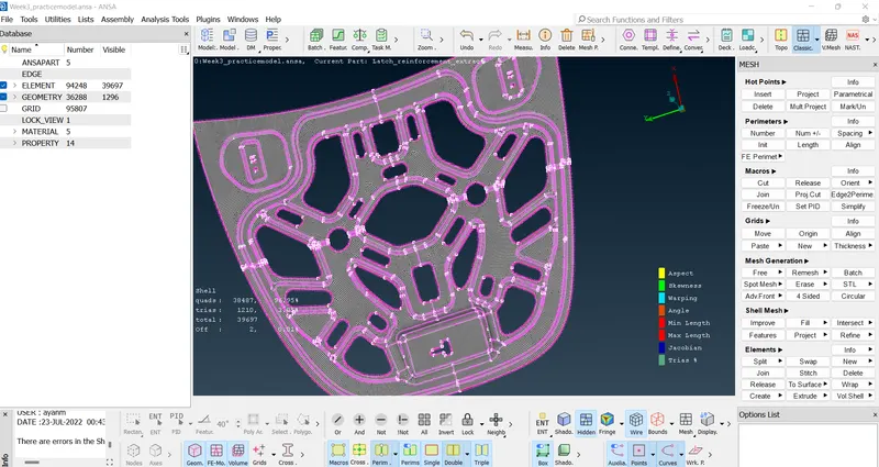
3. LATCH_REINFORCEMENT >MID-SURFACE >Geometry Check/Defeaturing >Classic Mesh:-
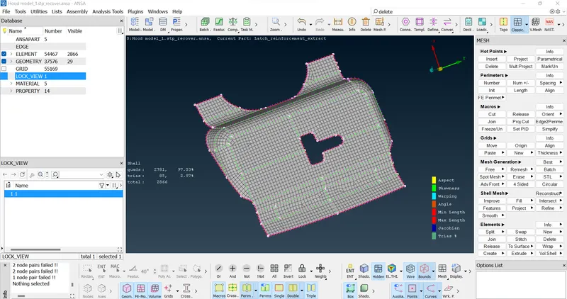
4.HINGE_REINFORCEMENT >MID-SURFACE >Geometry Check/Defeaturing >Classic Mesh:-
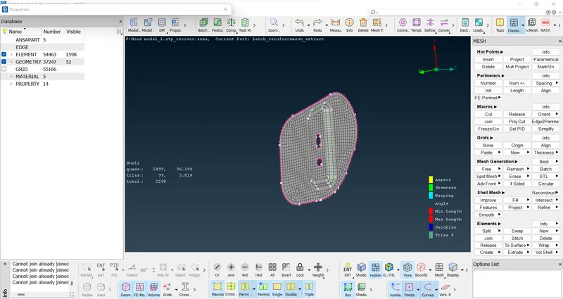
Finally, after creating the mesh and clearing for quality criteria, the mesh is mirrored for the outer panel, inner panel, and hinges by going to Utilities>Transform>Copy. All the entities to be mirrored are selected and then mirrored using the mirror 3 points plane option. Then, the mesh is checked for equivalence by changing to the Topo module. The model is checked for any free CONS and pasted using the Topo tool if any. Again, the mesh is checked for quality criteria. Finally, the shell element representation is changed by going to Utilities>Quality Criteria>Presentation parameters and enabling the 'Draw shell as solid'.
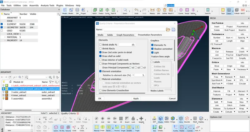
LEARNING OUTCOMES :-
- For performing geometric clean up,
geometry - execute - finding - fixing manually/ auto fix
2.for Mid surfacing,
- Topo - faces - offset -select face-enter offset value/direction- ok
- Extraction of Mid surface by manual as well automatic method.
- (If incase any original faces or model got deleted during mid surface extracting then bring them back with use Undeleted>topo.)
3.for mid surface extraction,
!Not - turn on PID - select the mid plane - enter
OR
Not - turn on PID - Select any thickness face - enter
4.for getting neighbouring elements
And - select - enter
5.for deleting hot points,
Hotpoint - insert/delete
6.for deleting un wanted lines,
topo - faces - cut -select - right click
If mistakely feature lines got deleted then bring them back with select lines> Release>topo.
7.for making the design good,
topo - auxiliaries - fine - enter
8.for removing triple cons,
topo - CONS - release - enter
- for joining two single cones,
faces -topo - select separate
10.for making mesh improved,
classic mesh - shell mesh - smooth / reconstruct
11.for changing trias position
classic mesh - element - split
classic mesh - grids - paste
[ NOTEs:
checks manager:
The Check command from Tool module shows a number of triple cons, double cons, crack parts and irregularities in geometry. The executed command also allow to fix certain irregularities automatically however, some of need to be fixed manually using either releasing cons or performing topology.
Midsurfacing of hood:
We perform midsurfacing of geometry either by using automatic midsurfacing command or by using manual offset method from faces option in module boxes. Same procedure is executed to create midsurface for both parts.
Setting up PID :
Setting up PDI allows us to provide some convenient properties such as thickness, and structural properties. A PID can only see in absence of an entity.
Once PID is set the geometry is ready for meshing however, there are various pre meshing procedures need to execute in order to get a smooth mesh flow with minimal trias. It is called as Quality criteria. These mostly includes setting up length between each perimeter as 5mm, followed by setting up mesh parameter consisting of max, min and target elemental mesh size, aspect ratios, trias %.
Quality Criteria:
Once all quality parameters are updated, we can process with meshing. To get a fine and smooth mesh flow it’s a best practice to divide geometry in small segments and perform mesh however, we need to perform defeaturing of geometry in order to qualify our quality criteria. Since we have set a targeted values for mesh, if a smaller mesh appears it going to not pass our quality criteria.
Geometry:
The geometric model must be preserved, we don't need to delete any part since, FE model is depended on geometry. We defeature by using cut tool from macro module, once they follow the acceptable pattern, we perform mesh.
Execute Mesh Generation tool from Modules on ANSA GUI. We need to use 'BEST' command to mesh. The BEST command itself is the best algorithm for mesh execution. We run the BEST command & select desired part on geometry then click mouse's middle button the mesh is generated.
Or we use ‘spot mesh’ (with shell mesh > improve, rest of other smother mesh flow in same order)
Generation:
For the sake of simplicity & to save time the half geometry can be meshed and copy to its symmetry body. After the mesh is generated, there is a possibility that it contains trias. A tria element will always be in a plane because it takes a minimum of 3 nodes to specify a plane. A quad element can warp if required depending on the applied load. Therefore, Quads are preferred over trias. The trias Elements are eliminated by either using mesh reconstruction command followed by splitting trias or moving them in specific position till they eliminate.
MESHING:
For both parts of Hood components are half meshed and later and transformed > copied symmetrically or using cutting in small zones for the whole faces by manually.
Finite Element Method reduces the degrees of freedom from infinite to finite with the help of discretization or meshing (nodes and elements). One of the purposes of meshing is to actually make the problem solvable using Finite Element. By meshing, you break up the domain into pieces, each piece representing an element. Here, ANSA stands for automatic net generation for structural analysis. ANSA is used here since, it’s a powerful pre-processor tool.
For the Importance of Quality criteria’s
Defeaturing entities: First check the measurement if it not between minimum targeted length or, In the hemming region (in the Outer panel’s bend region), Elements will fail for the Min length error due to the very small surface to capture the curved surface. ]
CONCLUSIONs:
Geometry clean-up, mid surface extraction, and 2D meshing of the given hood model were successfully done enabling the 'Draw shell as solid'. And all the elements pass the quality criteria. All the features in the model are captured properly with good mesh flow. Tria concentration is kept low.
WORKING MODEL:
https://drive.google.com/file/d/1HyNXvT7iC5uE38qTRizBVk9kJkr7hQnH/view?usp=sharing