Week 3 - 2D meshing for sheet metal
AIM: To clear the geometrical errors and mesh with the given Quality criteria.
Also assigned the thickness and different PIDs.
Given CAD Model: Car Hood Panel (Sheet Metal).
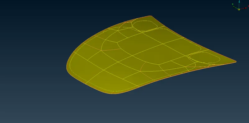
HOOD PANEL
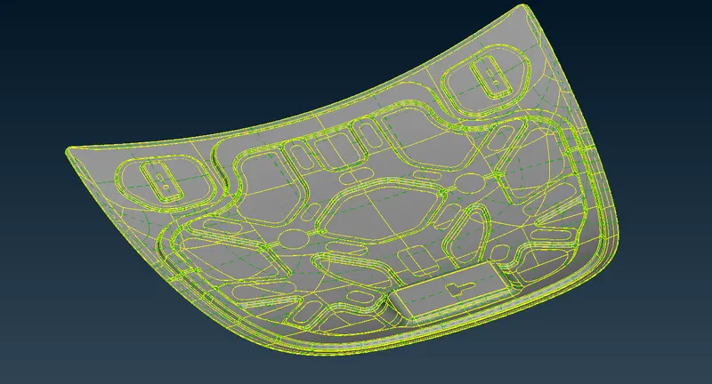
Inner part of Hood
QUALITY CRITERIA AND MESH PARAMETERS:
A low-quality mesh will not only result in inaccurate simulation results but might even cause the solver to produce an error due to instability.
The given quality criteria are shown below which is required for this model.
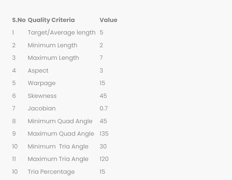
PROCEDURE:
01. Import the CAD Geometry.
Importing the CAD model so we are able to see the model on our ANSA GUI.
Go to File and click open or you can use the shortcuts key (CTRL+O)..
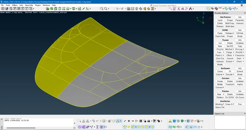
After importing the CAD file, the Ansa GUI looks like this.
02.Geometry Checks and Clean up.
Geometry cleanup is an integral part of meshing activity. You should have at least basic knowledge of CAD.
Before starting the job geometry should be carefully checked for:
- Free edges
- Duplicate surfaces
- Small fillets
- Small holes
- Single cons
- Cracks
- Overlap faces
- Needle faces
- Collapsed cons
- Unchecked faces

CAD with Errors
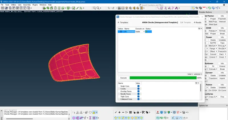
Clean up the errors
03. Skin and Mid surface Generation :
Mathematically elements thickness specified by user is assigned half on element top and half on bottom side or in other words the
mid surface is generated to reduce the complexity as by simplifying the cad model and we get more accurate simulation results in
shorter time. Hence in order to represent the geometry appropriately it is necessary to extract mid surface and then mesh on the mid surface.
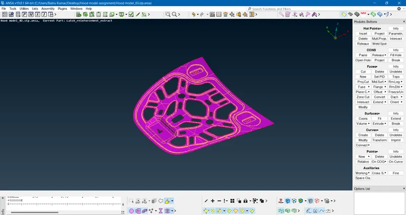
Inner Hood Panel Mid surface
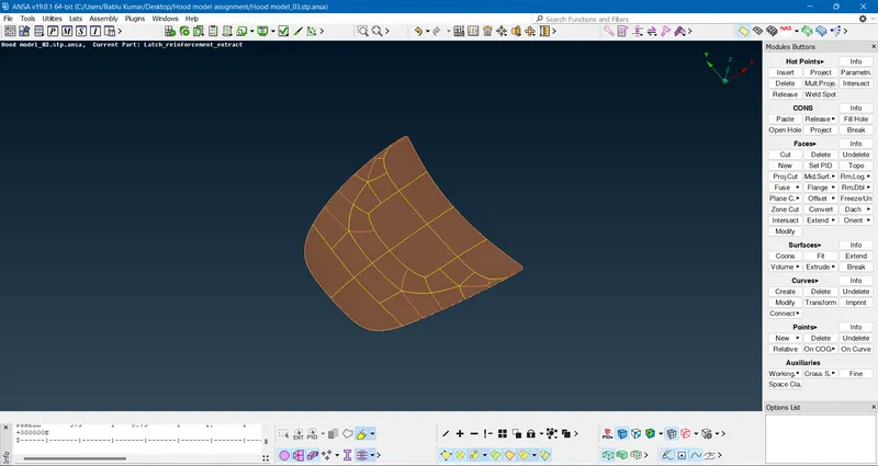
Outer Hood Panel Mid surface
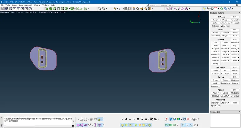
Latch Mid surface (1)
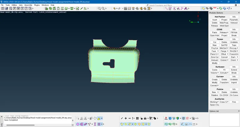
Latch Mid surface (02)
04.Set the PID and Thickness
During taking the mid surface or after taking the mid surface you can assign the different PID to the different part of the
models and also assigned thickness to them.
05.Shell and Solid Meshing
- The basic theme of FEA is to make calculation at only limited (Finite) number of points and then interpolate the results for entire
- domain (surface/ Volume). Any continuous object has infinite degrees of freedom and it’s just not possible to solve the problem in
- this format. Finite Element method reduces degrees of freedom from infinite to finite with the help of discretization that is meshing (Nodes and Elements).
- After the meshing use have to release the mesh to get the final FEA model.
- Note – For Casting and molding products we generally use Solid Meshing.
In this project, I have used a shell mesh for meshing the given model because it is a sheet metal component and gives good results.
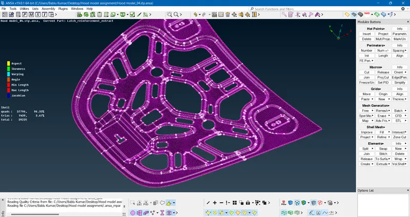
Inner Panel Mesh
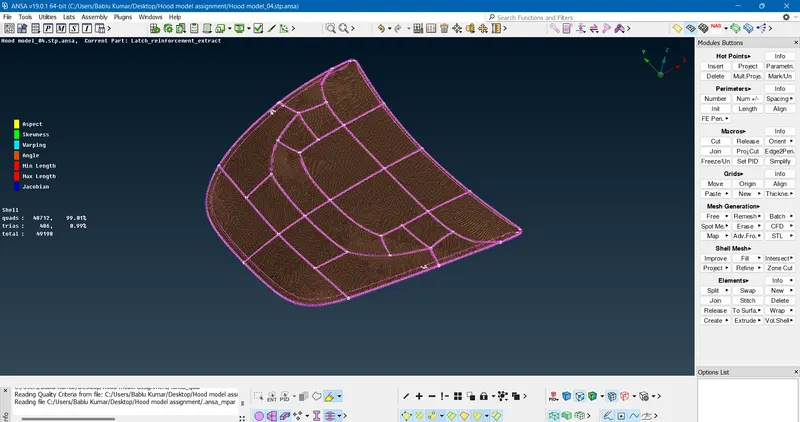
Outer Panel Mesh
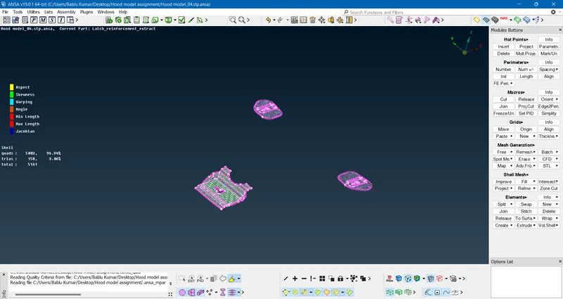
Latch Mesh
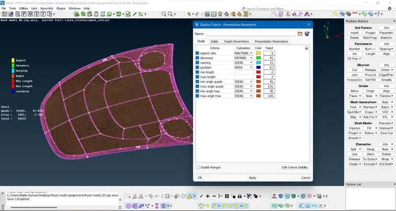
06. Quality Criteria of Elements
Every product which is been produced will go through the set of quality checks. If quality checks fails or not follow the requirement
parameters then other steps like BC (Boundary conditions) and applying loads will not be feasible. That why quality checks are performed.
07. Mesh Improvements
In this phase we check the mesh flow and quality of the mesh and if there is any chance of improvement or any change that
can be improve the mesh in any direction will done.
Outcome:
- Able to Clean up the any complex CAD model or geometry.
- Able to generate or extract the Midsurface.
- Able to create the proper mesh on the component.
- Able to clean the quality errors or off element of the mesh.
- Maintain the proper mesh flow.
Conclusion:
By following all these steps we get the final FEA model for the simulation or solver.
This is the link for the model... Car Hood panel