Week 3 - 2D meshing for sheet metal
Q - 3
For the given Hood model, Take the mid surface for all the components after checking the geometrical errors and mesh the mid surface with the given element Quality criteria. (Refer the table Below for the Quality criteria)
|
S.No |
Quality Criteria |
Value |
|
1 |
Target/Average length |
5 |
|
2 |
Minimum Length |
2 |
|
3 |
Maximum Length |
7 |
|
4 |
Aspect |
3 |
|
5 |
Warpage |
15 |
|
6 |
Skewness |
45 |
|
7 |
Jacobian |
0.7 |
|
8 |
Minimum Quad Angle |
45 |
|
9 |
Maximum Quad Angle |
135 |
|
10 |
Minimum Tria Angle |
30 |
|
11 |
Maximum Tria Angle |
120 |
|
10 |
Tria Percentage |
15 |
ANS:-
Aim:- to obtain a good quality of mesh for the given hood model
Procedure:- following steps followed.
1. Geometry check
2. Mid surfacing
3. symmetry plane cut
3. setting length of elements.
3. assigning thickness.
4. setting given quality criteria.
5. meshing the model.
briefly discussing above steps as below.
1. Geometry check:-
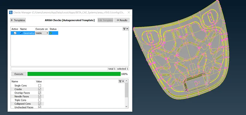
geometry checkup done with ticked parameter listedd in following pictures
found issues with tripple cons crack and overlap and resolved by usin auto fix option.
we have obsorved 100 % ok for geometry check
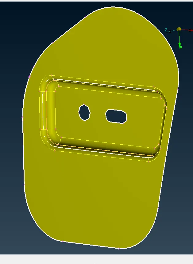
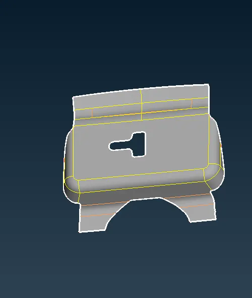
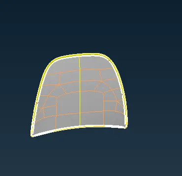
2. Mid surfacing:-
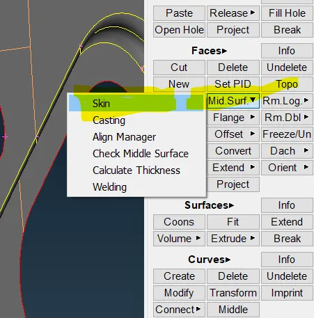
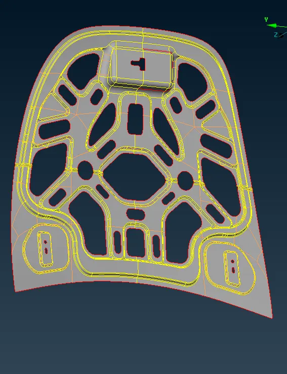
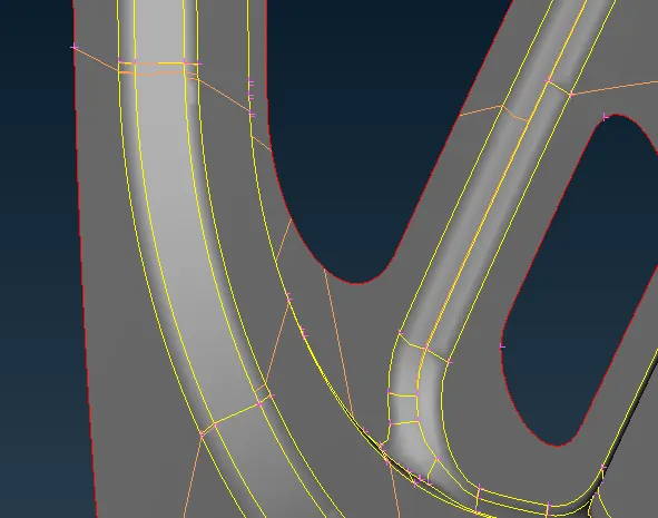
Mid surface is obtained by auto mid surface
3. symmetry plane cut:-
two planes are symmetrical geometry, we have used plane cut command to cut plane in middle and after completing meshing
transform command used to get complete plane as required .
by using this command we reduce at least half of the time required.
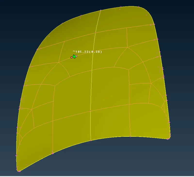
4. removing construction line:-
we have removed the feature which is not affecting the actual geometry of the plan
by removing unwanted construction line we will get a good mesh flow.
3. setting length of elements.
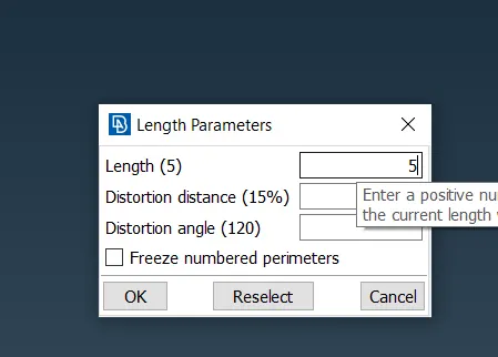
we have set element length as 5 for perimeter and macros.
4. assigning thickness.
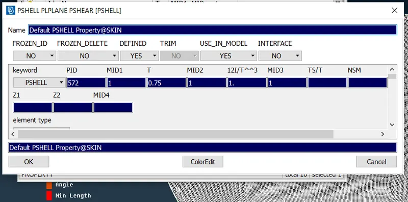
5. setting given quality criteria.
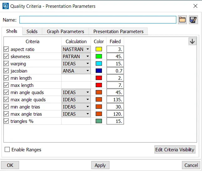
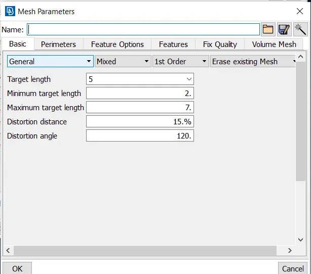
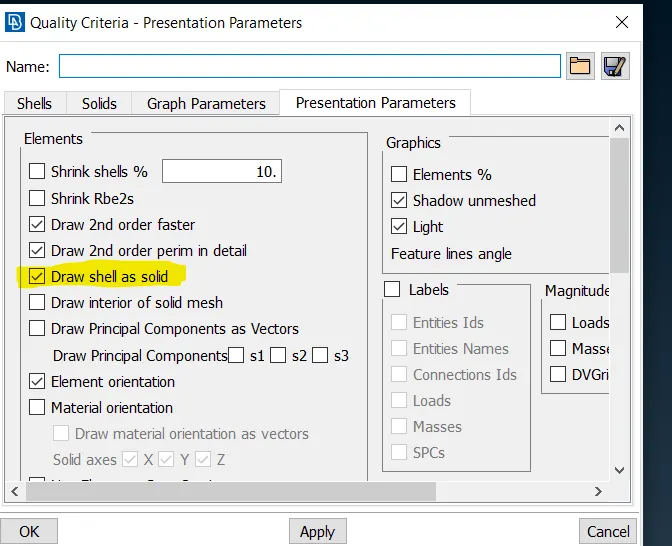
model is saved as solid, which is askedin the challenge.
6. meshing the model.
1. meshing is done with best command in mesh generation.
2. many faults observed, reconstruction command used to reduce possible faults.
3. 100+ faults still observed checked all the faults solved to least manually.
4. multiple commands used to ensure 0 faults.
5. split, swap, paste, smooth, reconstruction, Grid move.
When it comes to Tria elements, there are a few thumb rules to be followed
-
The Tria elements should never be opposite to each other
-
No Tria elements should be connected back to back
-
No Tria elements should be on the edge of the geometry
-
No Tria elements should be near the holes
-
No Tria elements should be on the feature and the fillets.
-
There should be less Tria concentration, i.e., there should be a considerable distance between Tria elements.
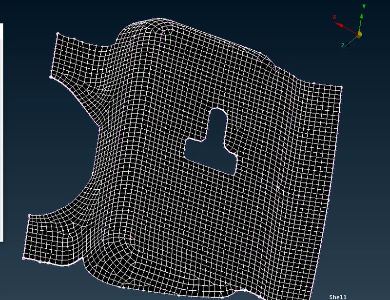
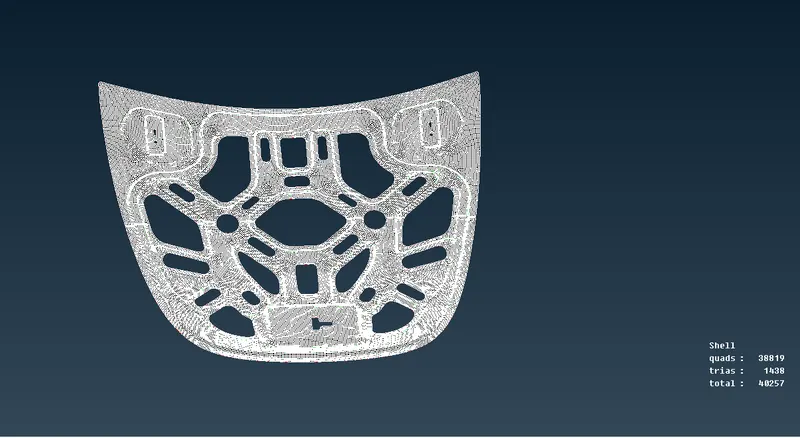
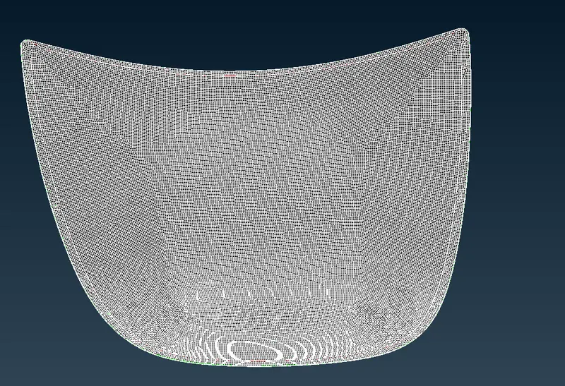
we have obtained the good mesh as shown in figure in good manner .
7. Learning Outcomes:-
1. multiple commands function learned and practised well.
2. manual mid surface extracting practised well.
3. practised well to ensure good quality of mesh.
4. several commands learned like plane-cut, transform-symmetry, saving mid surface as solid.
8. Conclusion:-
we have completed the meshing of hood model with given quality criteria.