Week 3 - 2D meshing for sheet metal
Aim-
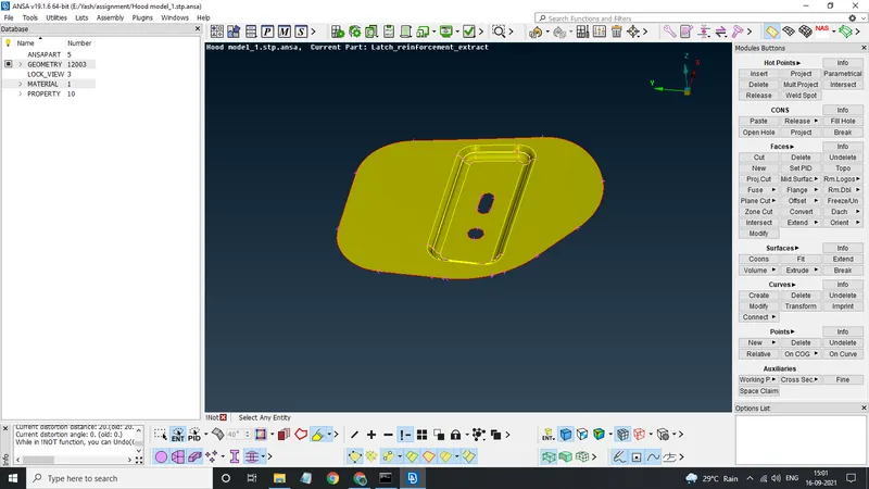
For the given Hood model, Take the mid surface for all the components after checking the geometrical errors and mesh the mid surface with the given element Quality criteria.
Given Data-
a) Cad Model
1-Class A Surface 2-Class B Surface
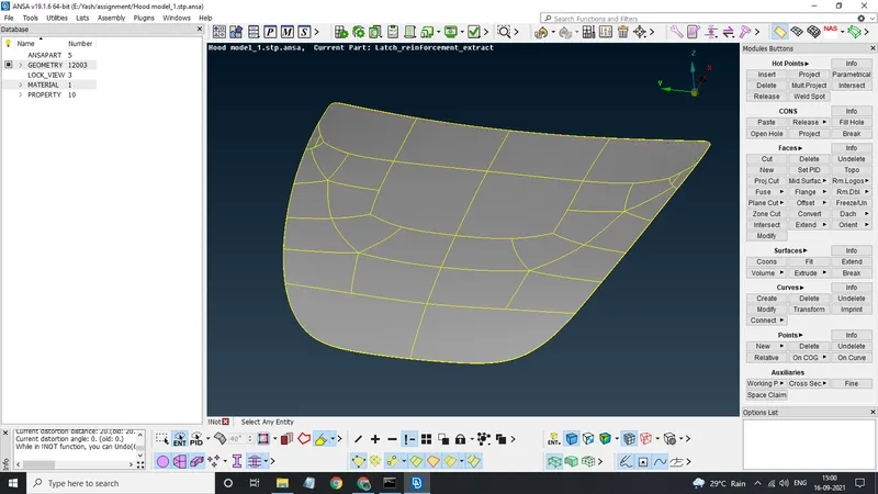
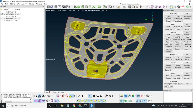
3- Latch 4- Left Hinge 5- Right Hinge
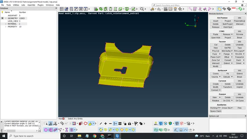
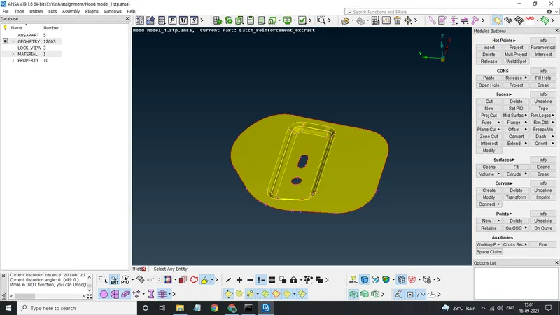
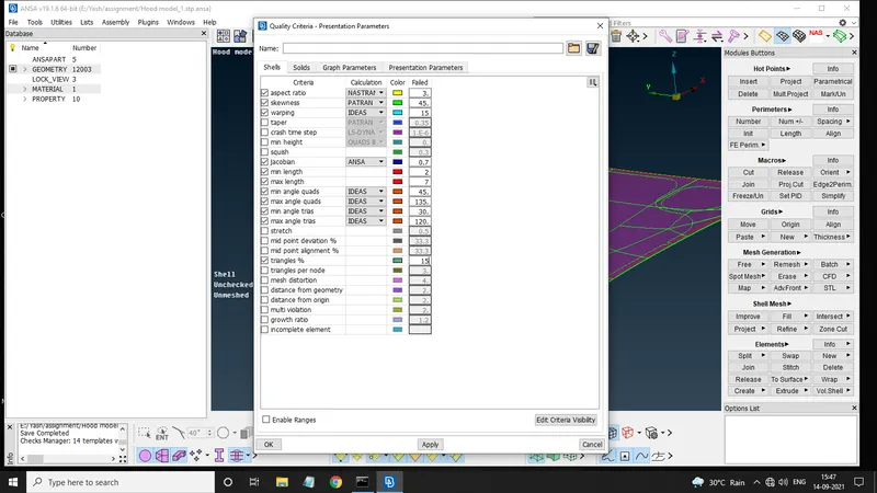
b) Quality Criteria
|
S.No |
Quality Criteria |
Value |
|
1 |
Target/Average length |
5 |
|
2 |
Minimum Length |
2 |
|
3 |
Maximum Length |
7 |
|
4 |
Aspect |
3 |
|
5 |
Warpage |
15 |
|
6 |
Skewness |
45 |
|
7 |
Jacobian |
0.7 |
|
8 |
Minimum Quad Angle |
45 |
|
9 |
Maximum Quad Angle |
135 |
|
10 |
Minimum Tria Angle |
30 |
|
11 |
Maximum Tria Angle |
120 |
|
10 |
Tria Percentage |
15 |
Procedure -
1) Check For Material - Here we first check the property ID of the geometry, That is material properties are defined or not,
if not then we have to mark them ON.
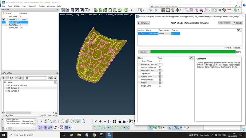
2) Check For Geometry - WE always have to check our geometries for any kind of geometrical errors by following these steps
CHECK MANAGER >> GEOMETRY >> Here Mark all options except UNMESHED MACROS and execute it
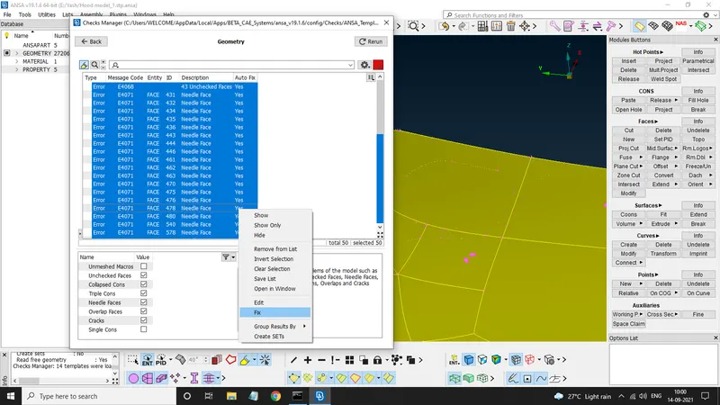
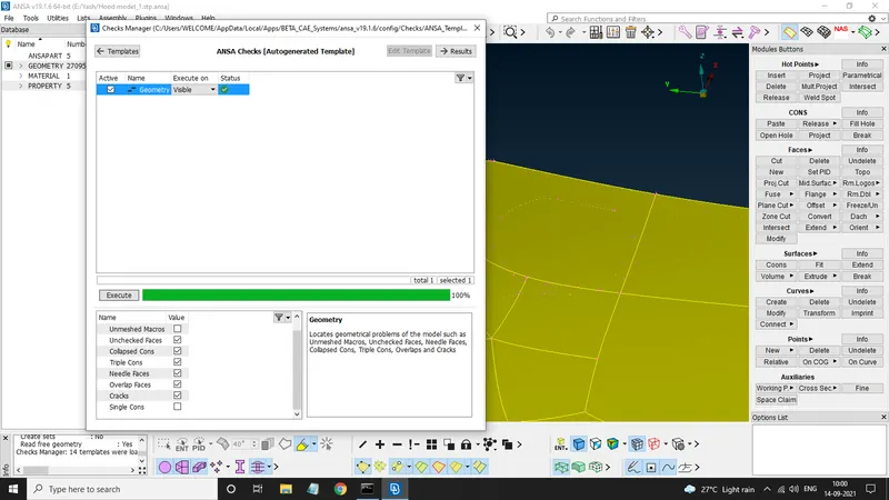
If there are any geometrical issues, they will be shown here, for this perticular model we had svevral issues, But these can be resolved by selecting all of them and RIGHT CLICK, Select FIX. Then again run this check and we will get this green status that means our geometry is all right.
3) Deviding The Components - Here we devide whole component into 3 parts
A class surface B class surface Latch & Hinges
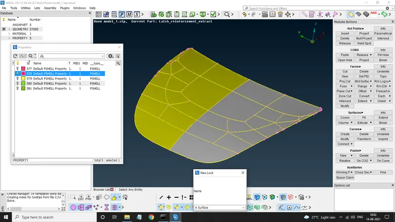
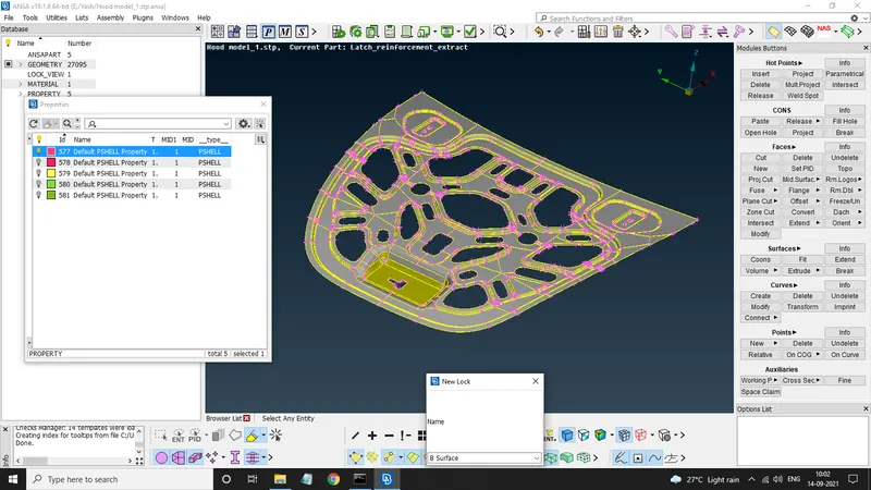
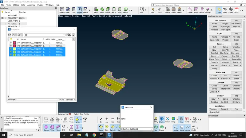
And Create a lock view for each of them.
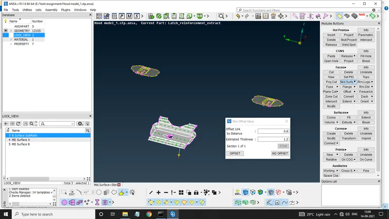
4) Creating Mid Surface - Since each component is a Closed Volume I prefferd using MID SURFACE>>SKIN
This command creates the mid surface for the selected object but also deletes the original CAD Geometry, we have to give OFFSET value for the mid surface
Thickness of Class A & B is 0.75mm so mid surface will be offseted to 0.375mm
Thickness of Latch & Hingers is 1.2mm so mid surface will be offseted to 0.6mm
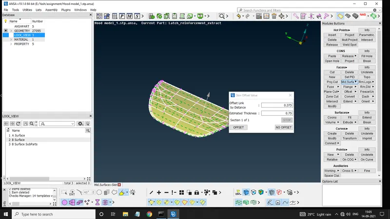
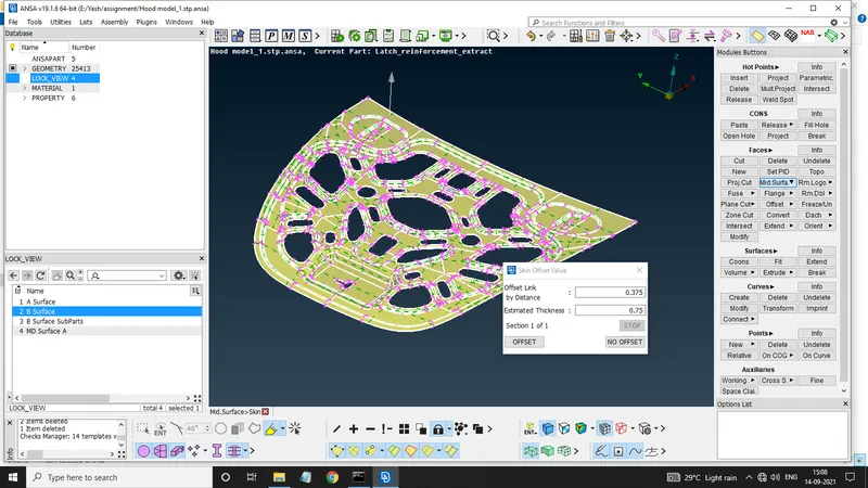
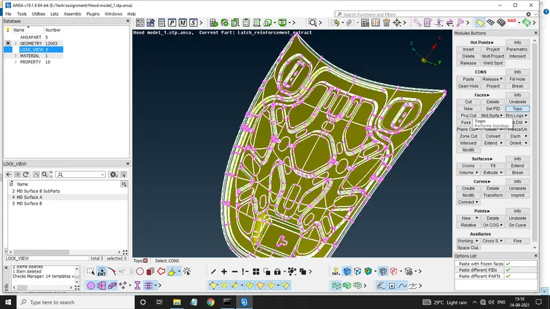
5) Performing Topology - Since we created mid surface there might be some surfaces not stiched together, so to stich them together we use TOPO on all components, for this select TOPO>>Select the geometry and click on cursor.
6) Final Geometry Check & Giving Seperate PIDs to each components - Here we give a final inspection to each component by again using CHECK MANAGER & After this we set PIDs for each component seperately.
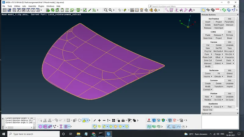
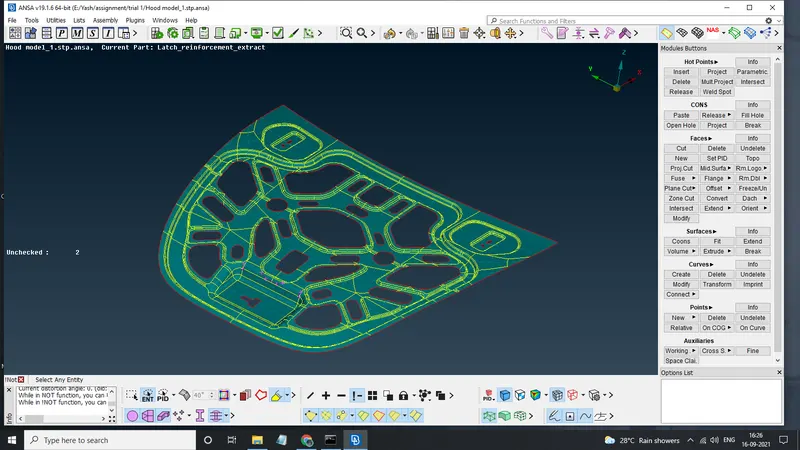
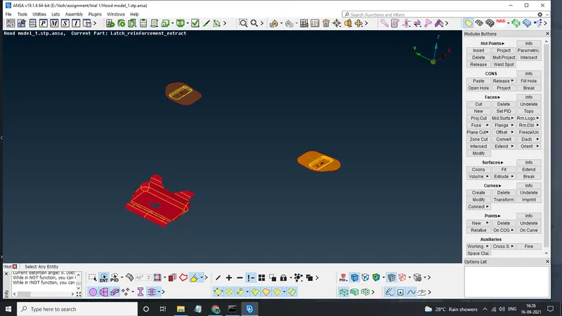
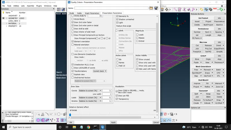
7) Quality Criteria, Presentation Perameteres & Mesh Parameters - Here we assign given quality criteria , change presentation perameteres And give mesh parameters.
( Element % & Details On Demand)
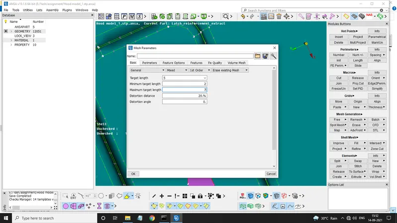
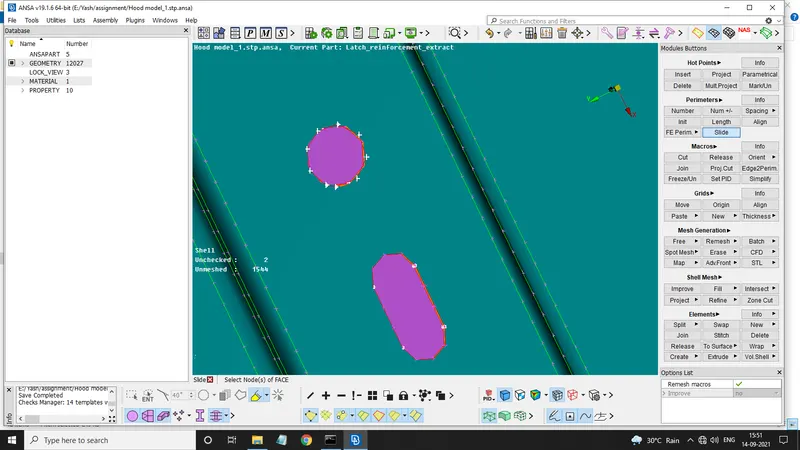
8) Giving Parameter Length & Correcting Size/Shapes of Holes - Go to PERAMETERS>>LENGTH here select the geometry that we want to work on first and assign the length(In this perticular Geometry 5mm), this will evenly space hotpoints at 5mm. After this go to PERAMETERS>>RIGHT CLICK>>SLIDE using this we will align the side of the hole parallel to its nearest edge of geometry. the use HOT POINTS>>MARK/UN fix them.
9) Changing Coons & Hotpoints to meet criteria - Since the given average length given to us is 5mm but there are many places in our geometry where distance between 2 conscutive hot points is less then 2mm (least acceptable distance) so we need to change somethings.
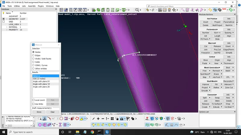 here edge fillete on class A surface is 1.59mm which is less then our least acceptable distance.
To change this we created an extra edge near the original edge (5mm apart from each other) so that by using this we can create a False fillete (Almost a triangle).
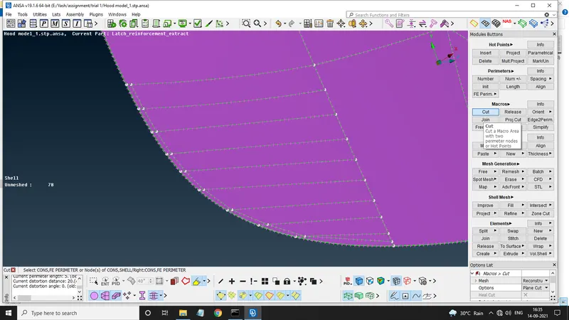
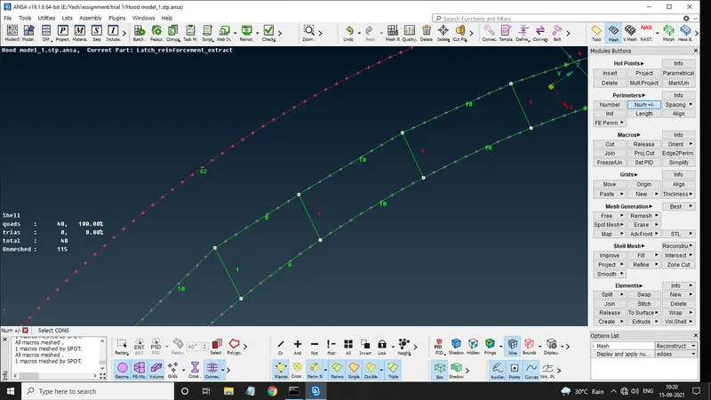
In Class B Surface there were many places where features are less then 2mm in size, to fix them we can either create new feature using MACRO>>CUT as shown below
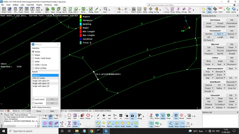
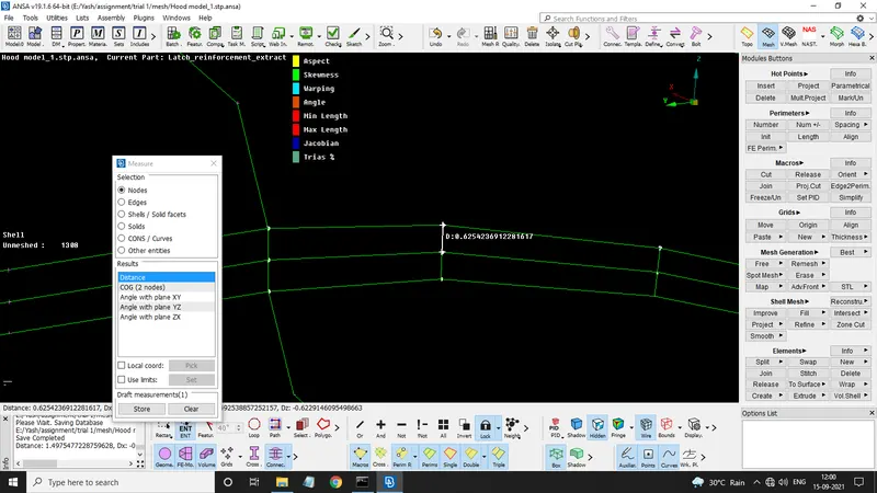
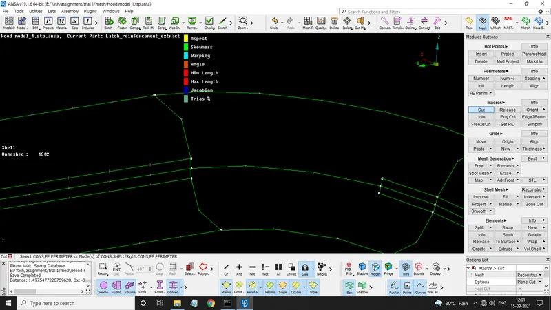
(Here in the first photo the distance between these 2 hot points was less then 2mm so we created a new line in between of prexisting lines and removed those lines.)
Or some features can be removed as this one 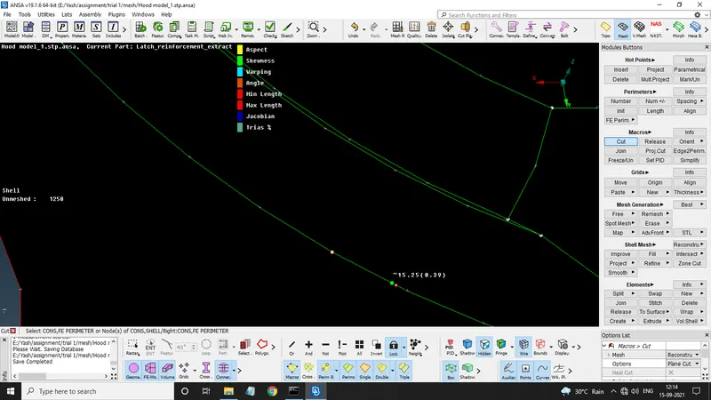
10) Mesh Generation - Go to MESH GENERATION>>RIGHT CLICK>>BEST>>SELECT and start selecting the faces that we want to mesh,
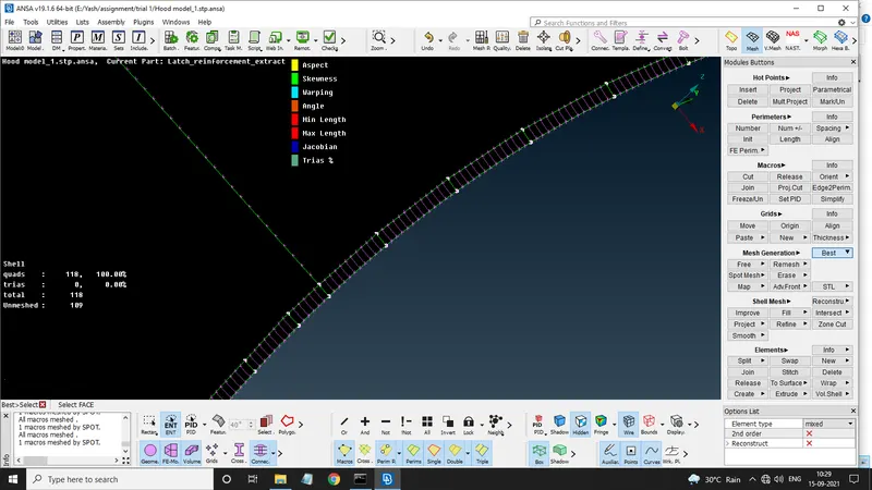
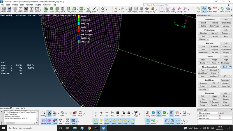
Go to HIDDEN VIEW to find out if thereis any element that fails in quality criteria and if there is then use SHELL MESH>>RECONSTRUCT and select the mesh, this will reconstruct the mesh to avoid the criteria failure, we can also use ELEMENTS>>SPLIT this will modify the selected element or node.
11) Criteria Check - During meshing we should always try to avoid tri elements, and due to given criteria our tri elements should not exceed by 15%, So after completing the meshing of all 5 components we found that
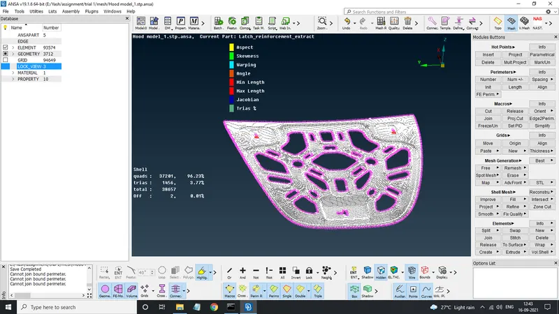
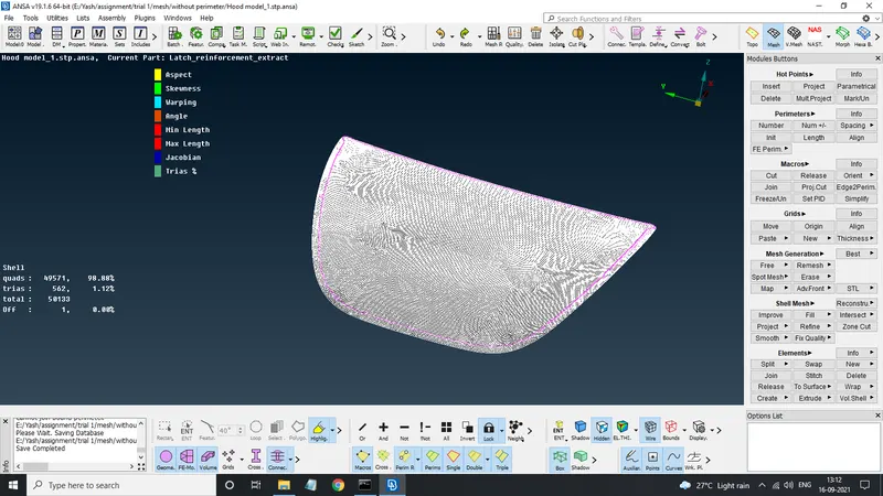
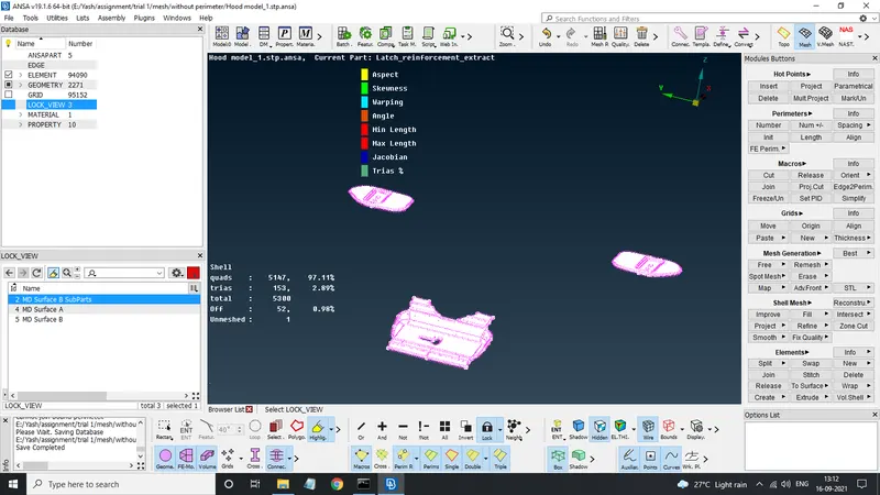
Tri Elements in our mesh is 2.31%
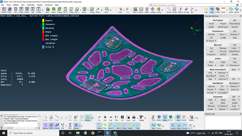
Therefore our mesh passes the quality criteria.
Conclusion - If geometry is not a closed volume then we have to do manual mesh by OFFSET, But since we had closed volume we did automatic mid surfacing , both method have there advantages and disadvantages such as time and accuracy.
- Cut/Constructing Lines helps in simplifing geometry therefore better mesh flow is obtained.