Week 3 - 2D meshing for sheet metal
OBJECTIVE
To mesh the given component after geometry cleanup and generate midsurface using ANSA and to check whether mesh follows the given quality criteria and to assign the thickness to the mesh.
PROCEDURE
1. The given model has 4 main components and they have different thicknesses. The Thickness of the components can be measured using the Measure tool in the toolbar.
2. The Length option is mesh module is used to get a proper view of the component and the feature lines. All the entities are selected for that.
3. To check geometry and cleanup the geometry, checks tool can be accessed from the upper toolbar Checks > Geometry. Check all the boxes for cleanup except for Single cons The geometric errors will be highlighted by the tool and they can all be selected, right clicked and fixed by clicking 'fix' . Some geometry cleanup require manual cleaning up.
MODEL GEOMETRY CLEANUP:
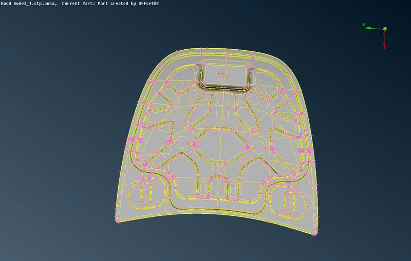
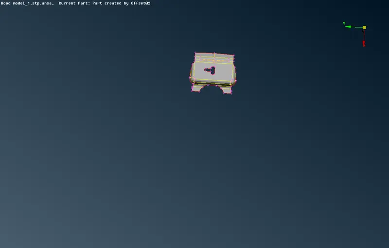
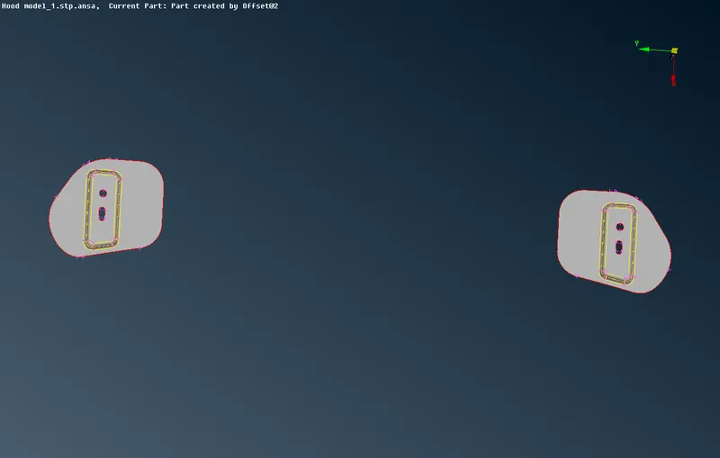
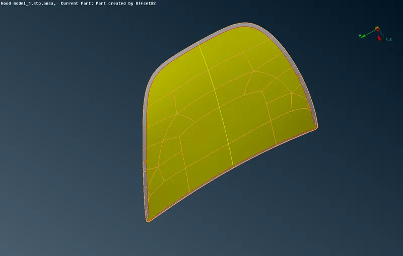
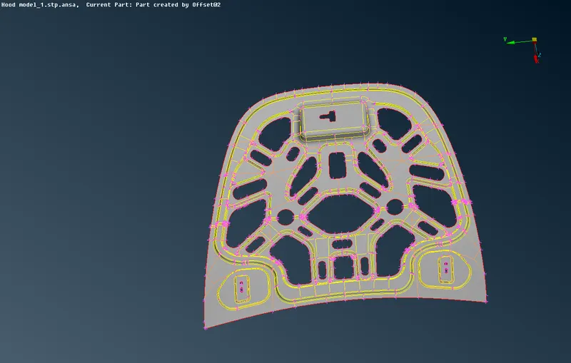
4. To create a property, go to properties from the upper toolbar and right click the list. Then go to New > PSHELL > PSHELL to create a new property ID.We can edit the properties of in that tab , here we have to assign thickness(T)to the component.Then the property is right clicked and select Apply. Then select the component you want to assign the thickness and click middle mouse button. This will apply thickness to the component.
5. Now we have to create midsurfaces for the components. This can be done using the 'midsurface' tool in the faces menu or using the 'offset' tool from the Topo mode. The offset tool is selected where after selecting the offset tool, it will ask us to select the surfaces to offset. We can select the surfaces on one side of the component. After that, we can assign the offset value The offset tool will show the direction of the offset with an arrow. If it is in the opposite direction of the required offset, the offset value needs to be in negative. We have to keep the original faces or it will delete the parent geometry after creating midsurface.The offsetted component can then be assigned their respective property, through the 'apply' option.
6. After midsurface is generated for each of the components, we can mesh the midsurfaces. First,we can assign the quality parameters as per the given criteria. We need to select the 'mesh parameters' and 'quality criteria' options from the top toolbar and then we can assign the values as per the table. The mesh type will be 'mixed' and minimum and maximum lengths would be 2mm and 7mm respectively.Target length will be ' Average'.
7.We need to assign the target length to get a proper mesh and go select Lenght+/- from the mesh module and select perimeter and select the entire component and give the length as 5.
8. To get better mesh flow and good mesh quality, the midsurface needs to be cleaned up and the surfaces are cut into smaller surfaces using the cut option in the mesh module . This will help get a better mesh flow.The inner extract and the outer extract are symmetrical , we can delete half of the surfaces and mesh the surfaces and can later reflect them using Transform->Symmetry-> Defauly symmetry plane and click okay.
MESHED COMPONENTS
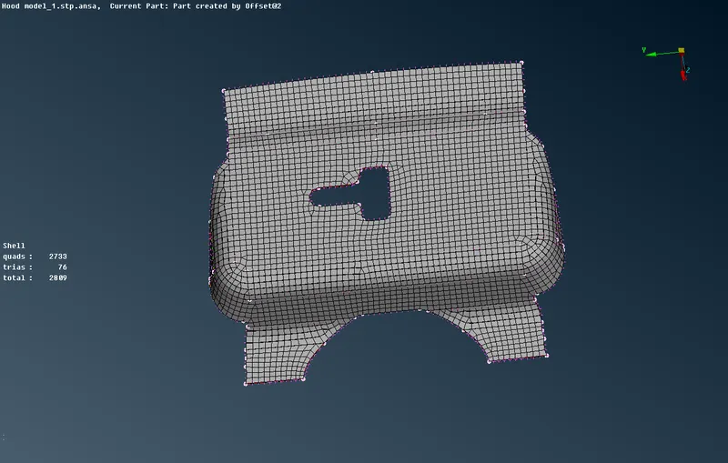
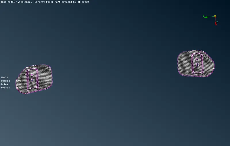
9. After cleaning up the surfaces and midsurface is generated, we can go ahead and mesh them. We need to use the 'best' mesh option, which can be accessed from the 'Mesh Generation' section. Its advised to start from the edges with redlines and split the surfaces in to smaller surfaces to avoid trias.
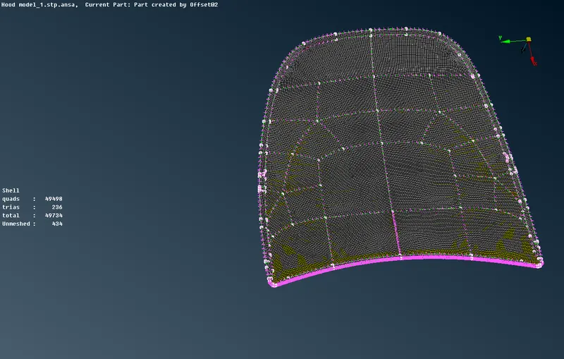
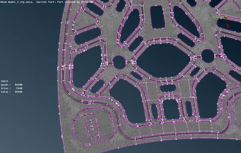
10. After meshing a region, check the mesh and see if it can be improved. If it can be improved, we can use the 'Reconstruct' tool from the Shell Mesh section in the mesh moduleor the Remesh option available to get different mesh on the surface which the Ansa AI gives and choose the best one.This process is repeated until we mesh the entire component.
11.Mesh quality can be checked by switching to hidden mode. The option is available on the bottom toolbar. The failing elements will be highlighted in the colours as per the list on the left side of the screen.
12.There will be some trias which will be unavoidable and needed for check element quality . Trias are okay but certain types of trias need to be avoided - like opposite trias or trias touching feature lines. Trias can be worked on using the swap, split, join and smooth tools. The first three are available in the 'Elements' section and the smooth tool is available in the 'Shell Mesh' section.
13.The opposite trias are taken care of by splitting the quads between them using the split tool, then joining the two adjoining trias formed (involving the opposite trias) using the join tool. The mesh can then be smoothed using the smooth tool to improve the mesh flow.
QUALITY CRITERIA CHECK:
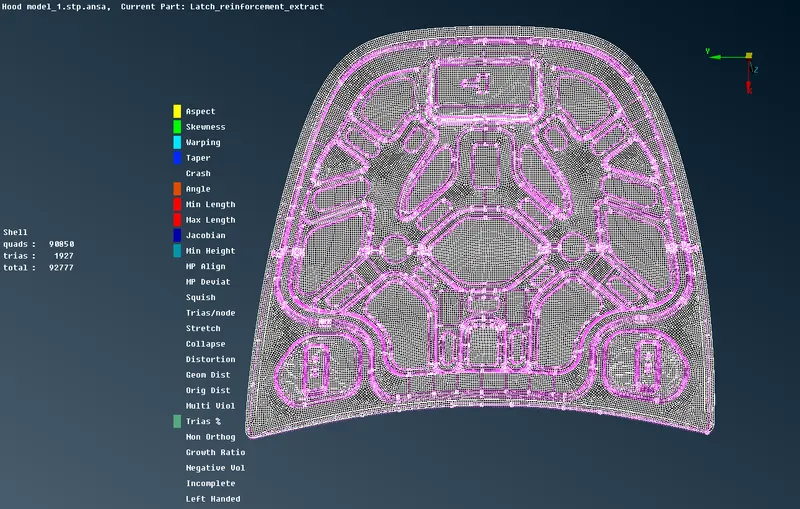
14. Finally, draw shell as solid needs to be activated. This can be done by going to Quality Parameters and accessing the Presentation Parameters tab. In that section, the 'Draw Shell as Solid' box needs to be checked.
LEARNING OUTCOMES:
Learnt about the various tools used in the Ansa and their functions.
Understanding about the geometry cleanup and how to midsurface a component manually.
Learning how to create and apply property and thickness to the component and mesh the surface.
To create a mesh with minimum trias and how to remove trias .
CONCLUSION:
The given model is meshed properly as per the given quality criteria after the geometry is cleaned up and the midsurface is extracted and thickness is assigned to them.
GOOGLEDRIVE LINK FOR MODEL:
https://drive.google.com/file/d/1XIsgixMvBdJLYdt9RYzVjKbzynmwKMRH/view?usp=sharing