Week 2 Railwheel and Track
Static structural analysis on the Railwheel and Track
Objective:
Perform a Static Analysis of the Rail wheel on a track and compare cases when bearing load changes.
Briefing:
Two cases are to be analyzed with 100000 N and 500000 N bearing load.
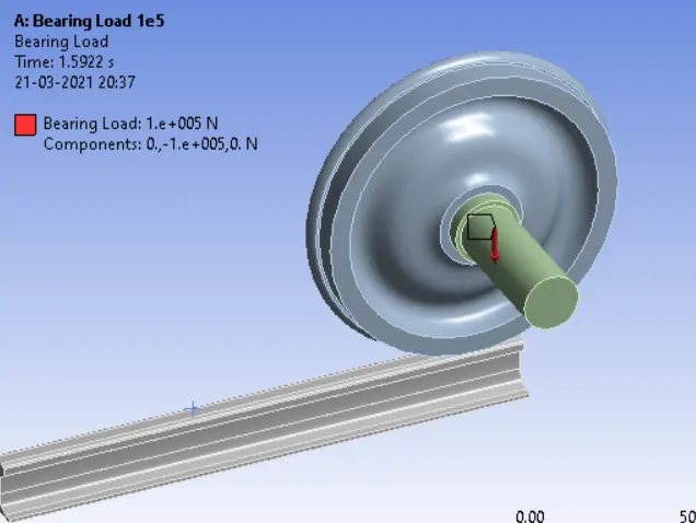
Bearing Load boundary condition simulates radial forces only. It is applied to the interior of a cylinder in the radial direction using a coordinate system.
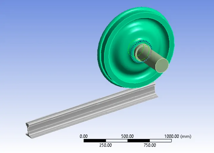
The model has three parts the wheel, shaft, and track.
Procedure and Setup:
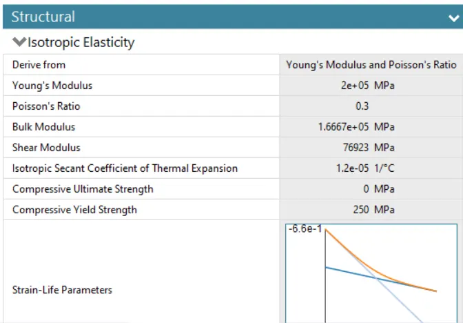
- Structural steel material is assigned to all the parts of the model.

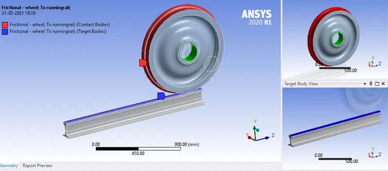
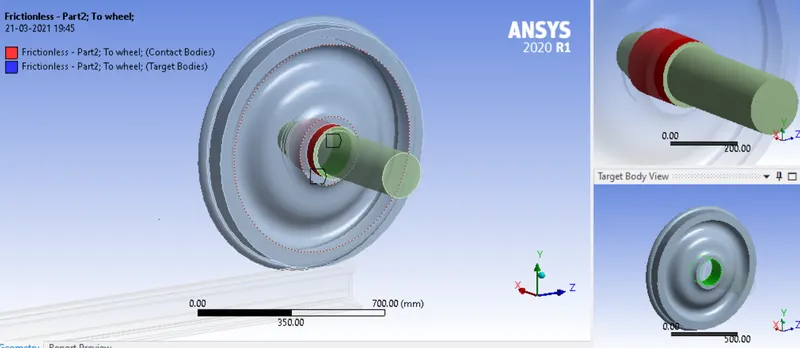
- Contact Definitions - two contacts are defined one for the contact between the wheel and track (Frictional), another one for wheel and shaft (Frictionless).
- Frictionless contact is provided with the assumption that the contact surface is a well-lubricated surface. In this case, the boundary condition is used to prevent one or more flat or curved faces from moving or deforming in the normal direction. No portion of the surface body can move, rotate, or deform normally to the face.
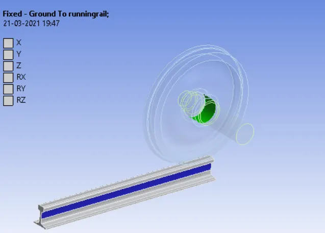
- Joint Definitions - 3 joints are defined for this simulation.
The track is Fixed using this joint.
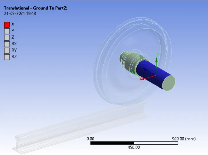
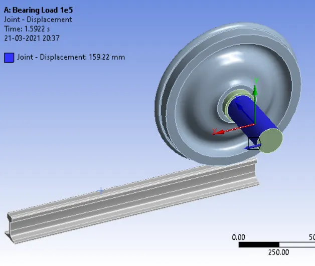
The shaft is given a Translational joint in the Global x-axis.
A Planar joint is given for the wheel that is rotated about the Z global axis.
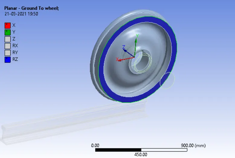
Boundary Conditions
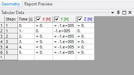
- Bearing load of 1.e+005 is applied to the shaft in the global y-axis for 5 load steps.
- Translational motion is given to the translational joint created before
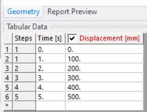
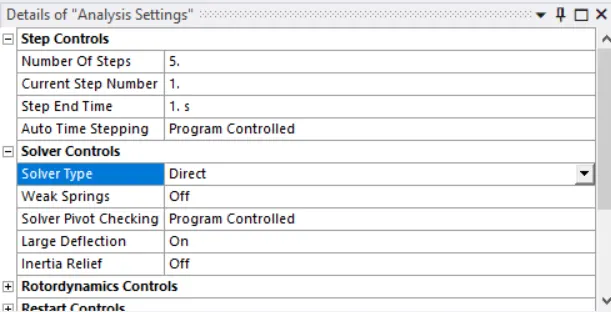
Analysis Settings
Direct Solver type is used in this case. A direct solver ( inverses the stiffness matrix), which is based on the Gauss elimination or LU decomposition; and an iterative solver in which errors are minimized and solutions are converged through iterative calculations.
Results and Case Study
Comparison of results :
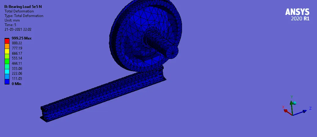
- We can see that under 500000 N bearing load the wheel goes into a plastic deformation ( yield stress limit is 250 MPa)
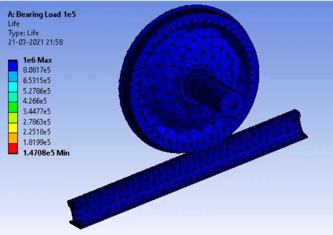
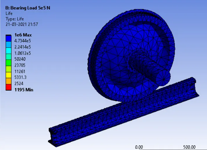
- Also, the minimum life cycle in the case of 500000 N bearing load is much lower than the 1.4708e5 cycle of 100000 N bearing load.
| Bearing Load / Parameter | Total Deformation (mm) | Equivalent stress (Mpa) | life cycle (min ) |
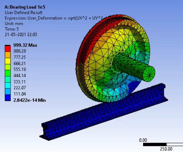
| 100000 N | 999.32 | 124.08 | 1.4708e5 |
| 500000 N | 999.25 | 537.59 | 1195 |
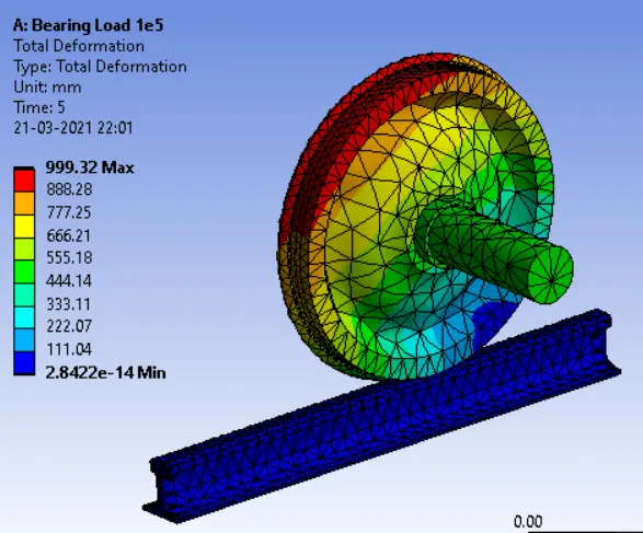
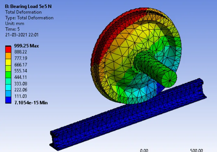
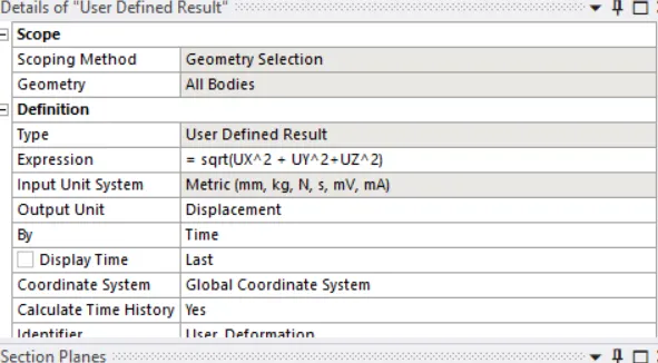
- User-Defined Total Deformation obtained from using the formulae (sqrt(UX^2 + UY^2+UZ^2) is the same as the value obtained through the default function.