Week 2 Railwheel and Track
RAILWHEEL AND TRACK SIMULATION
OBJECTIVE:
The objective of this project is to perform a static structural analysis on a rail wheel and track setup and analyze the setup under two different case scenarios and to determine the Equivalent stress, Total deformation, and equivalent strain data
Case 1: Multiply the bearing load by 5 times and compare the results with the load of 100000 N (As done in week 2 video). Compare the Total Deformation, Equivalent stress and the life under both the loads
Case 2: Implement a User defined result and calculate the Total Deformation from this result and check if it is the same as that obtained by the inbuilt result by ANSYS for a load of 100000 N.
PROCEDURE:
- Create a new static structural simulation
- Import the paramteric .x_t file onto the Spaceclaim GUI
- Then the model module of static structural is again updated.
- Open the model in ansys mechanical module.
Material assignment
- Add structural steel as the desired material to both the geometries.
Contact sets
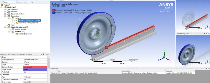
- Make sure two contact sets are defined between the rail wheel and track and another set for the rail wheel and shaft.
- Set the coefficient of friction in the first contact set between the track and wheel as 0.3
- Define the contact between wheel and shaft as frictionless.
Joint
- A fixed joint is created for the wheel and track
- A translational joint is created with the shaft as the scope along the x-axis
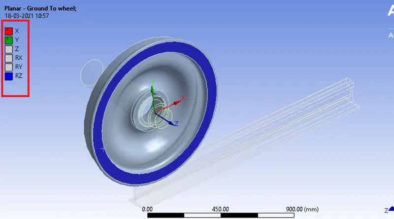
- A planar joint is create for the wheel part so that it doesn't slip aways from its translational axis along the x-direction
This planar joint allows translation along x and y axis and rotation about the z-axis (as shown below)
Joint load
- A joint load is defined on the translational joint on the saft. It is defined to move about a distance of 100mm at each time step.
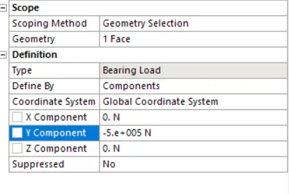
- A bearing load is also defined on the wheel with a load of 1e5 N at the negative y-axis
RESULTS:
The following results are obtained
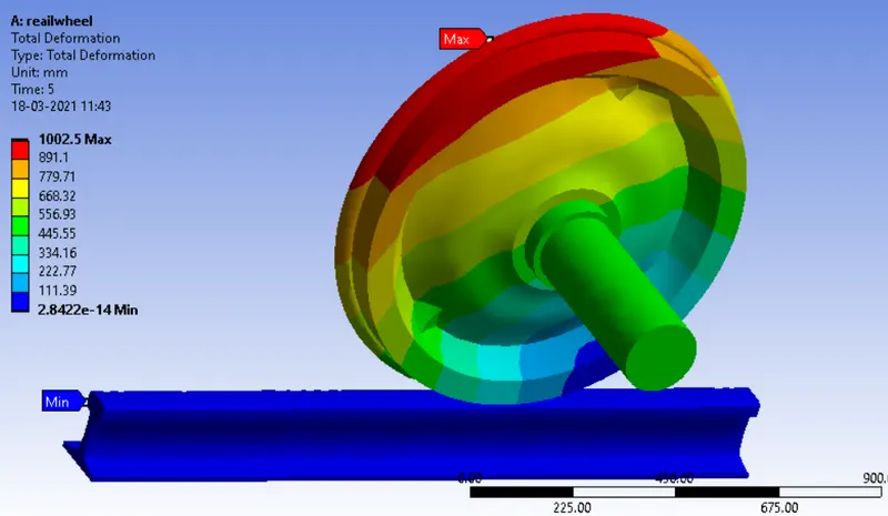
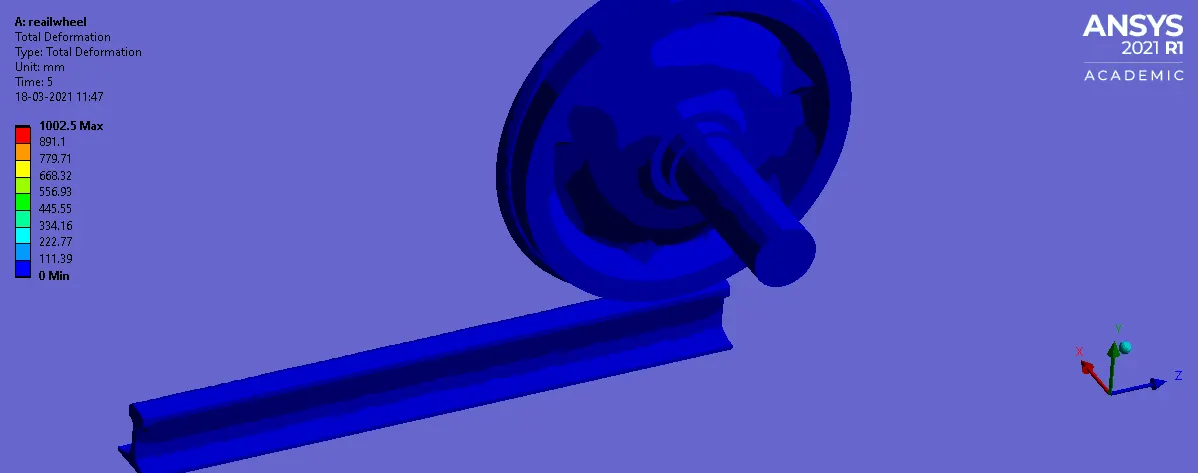
Total deformation
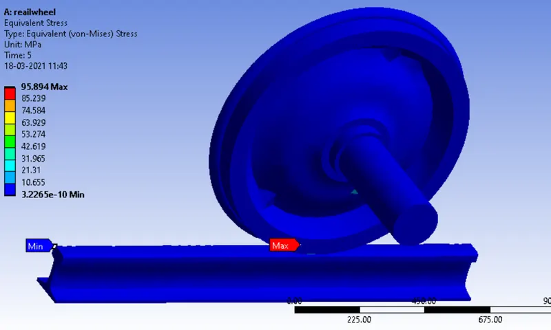
Equivalent stress
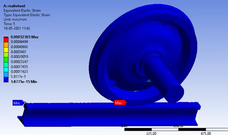
Equivalent strain
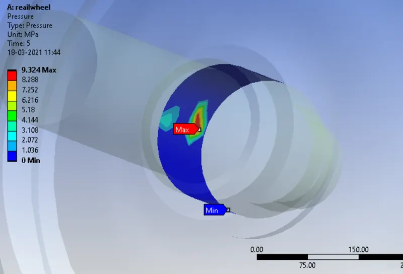
Contact pressure (Wheel and shaft)
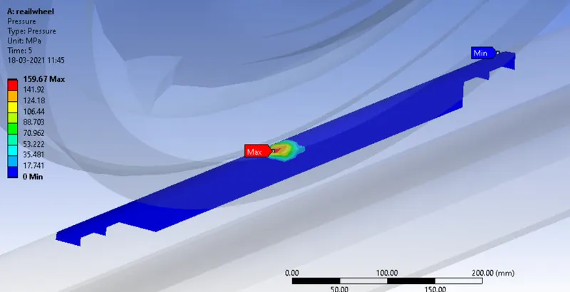
Contact pressure (Wheel and track)
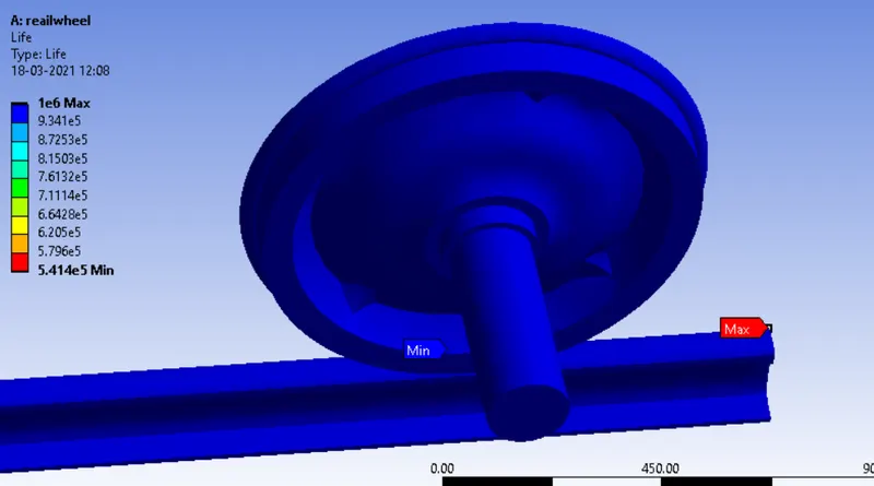
Life
CASE: 1
The bearing load that acts long the -y axis is incremented to 5e5 N
The following results were obtained
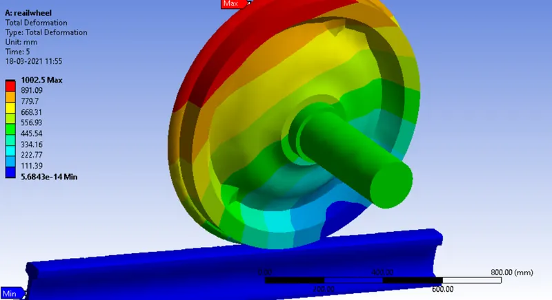
Total deformation
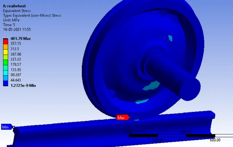
Equivalent stress
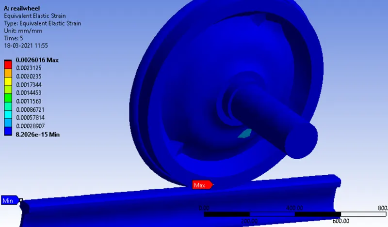
Equivalent strain
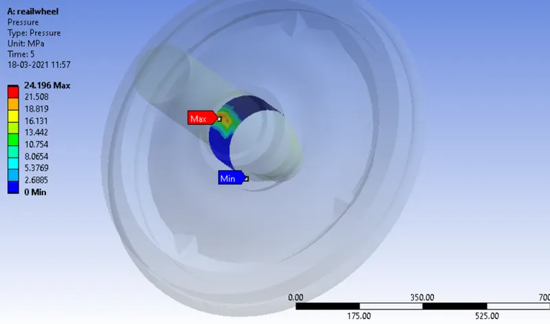
Contact pressure (shaft and wheel)
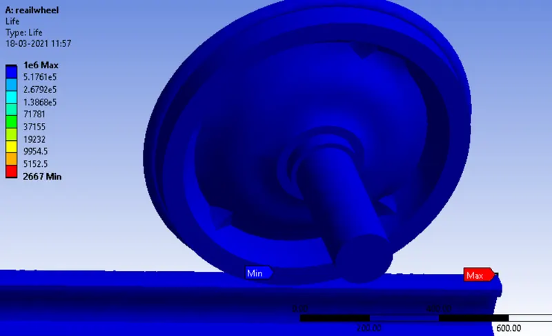
Life
CASE: 2
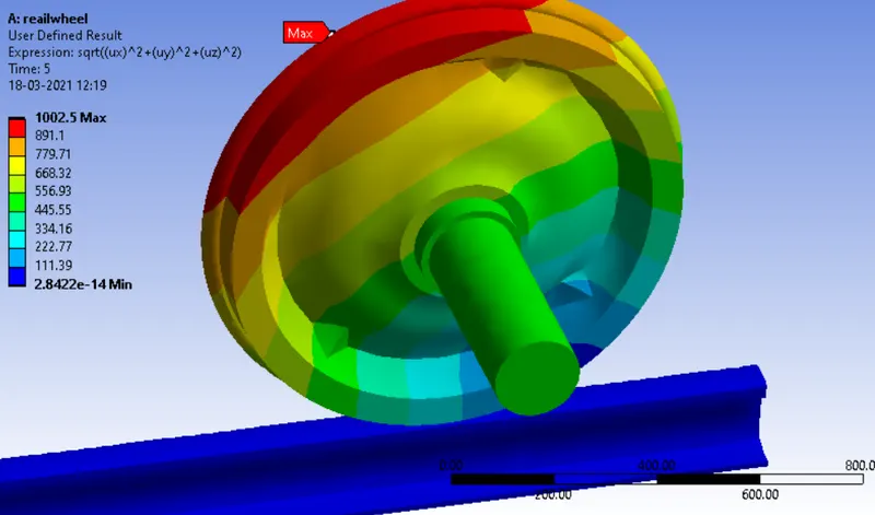
Another feature offered by the solver package is its capability to compute user defined results based on expressions.
In our case, to compute the total deformation occurred in the model, the total deformation has to be defined in the user defined expression area.
The total deformation formula takes into consideration of the deformation along the x, y and z axis. Hence it can be computed as : `u = sqrt((ux)^2+(uy)^2+(uz)^2`
The results is shown below
CONCLUSION
By comparing with the case 1 study, it is obvious that the equivalent stress, total deformation and strain would reach a value more than the one resulting from a bearing load of 1e5 N. The life of the model at the contact regions also had a significant minimum value and a high contact pressure at the contact regions.
We can also conclude that the results generated from the user defined profile section for the total deformation is similar to the pre-defined total deformation result.