static structural analysis on the Railwheel and Track setup using Ansys Wokbench.
Aim:- Perform a static structural analysis on the Railwheel and Track setup
Objective:-
CASE1:- Run the Static Structural Analysis with the bearing load 100000N
CASE2:- Run the Static Structural Analysis with the bearing load 500000N
CASE3:- Implement a User-defined result and calculate the Total Deformation from this result and check if it is the same as that obtained by the inbuilt result by ANSYS for a load of 100000 N.
Methodology
-Called out the respective system form the Ansys Workbench for the respective Simulation (In our case it's Static Structural)
-Set the material cards for the simulation
-Import the geometry, mesh it, and set appropriate conditions for the simulation.
Procedure:-
-For this assignment, I had got Railwheel and Track setup for structural Analysis. So I had set the Three different material card for three different cases
[NOTE:- the procedure for setting up the material and card is the same for all three cases, so only one case is explained here]
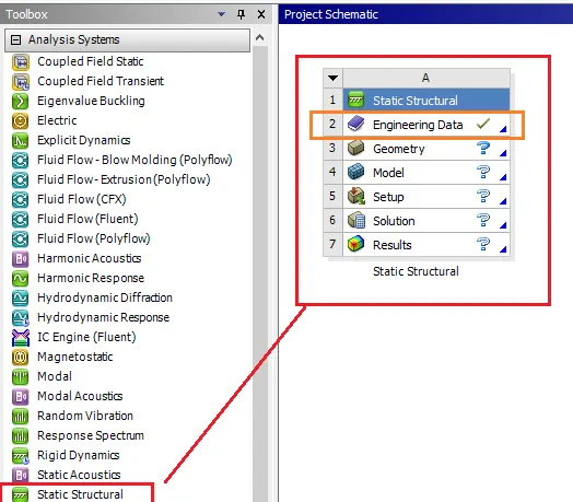
In Ansys Workbench there is a Static structural system available for static structural Analysis. As you can see in the image.
Engineering data option used to select or set up the Material Cards. The image below is one of the great examples of that
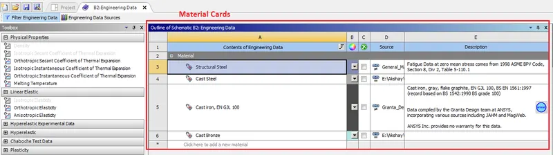
this window will open after clicking on the "Engineering Data" option and as you can see we can set the different material available in the Ansys workbench. For the materials which are not there, we can easily set the new material cards.
The second option is "geometry" from where you can create the New geometry using the "SpaceClaim" option or import the geometry in the "Desing Modeler".
For this assignment, we have geometry so I had used the import option to called out Geometry. The "Model" deck help us to mesh and Define different boundary condition over the geometries.
Contacts
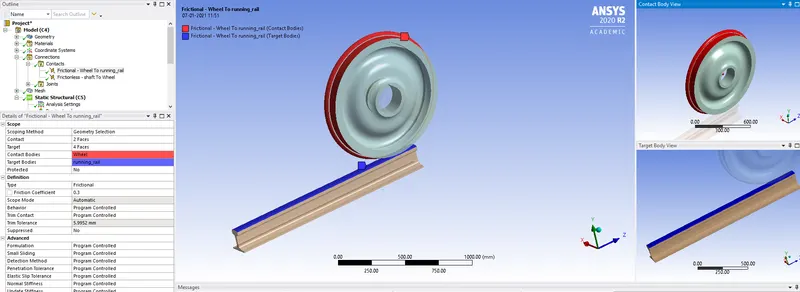
For contact deployment over the two neighboring components, we have to select the Contact Bodies and Target Bodies. In general, Ansys will automatically identify that and try to deploy it. if the Auto deployed contact is not acceptable then the user can flip or change it.
The choosing of which should be the Contact body and which should be the target body is a tricky one. There are some guidelines for that,
1) Mesh Density:- So the Contact and Target bodies are dependent on Mesh Density. The geometry having Dense mesh has a higher number of detection points to detect the contact. These contact detection point either be nodes or integration points which is lie over the element. Suppose in the above case if we had Coarse mesh on the wheel and the Dense mesh on the rail than at some point because of the coarse mesh (less contact detection points) and wheel-less contact area while rolling will miss the detection points and that may result into the penetration. So the higher Dense mesh Geometry always preferred for the Contact body.
2) Geometry:- Generally the convex-shaped bodies like curve, ball, round objects are considered for contact bodies while the Flat/Concave bodies are considered as Target Bodies.
It's not always true, suppose if the sharp edge is in contact with the surface then the respective side of the surface edge or the corner always consider as the contact side while the flat surface considers as the target body.
This is because the round/ circular object or the edge of the component within contact with a flat surface all has less cross-section/contact area.
3) material Stiffness:- Soft material should be always consider for the contact side and Stiff material for the Target side.
Joints:-
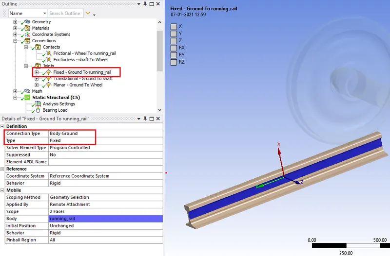
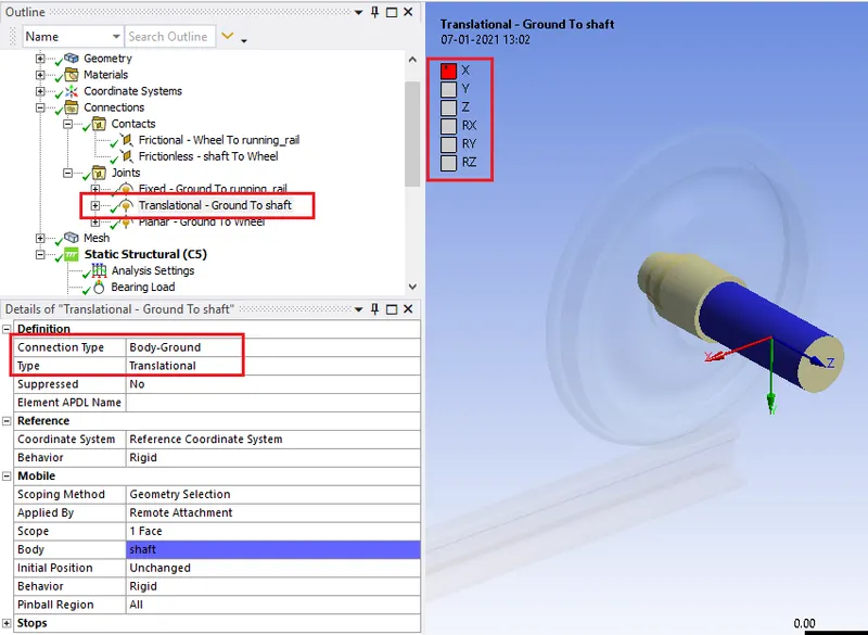
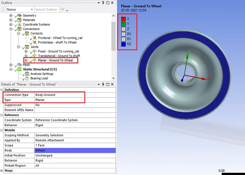
After contact definition it's time to add joints, Here we are using gears so we have to define the axis of rotation, displacement, and plane of reference.
Mesh Deployment
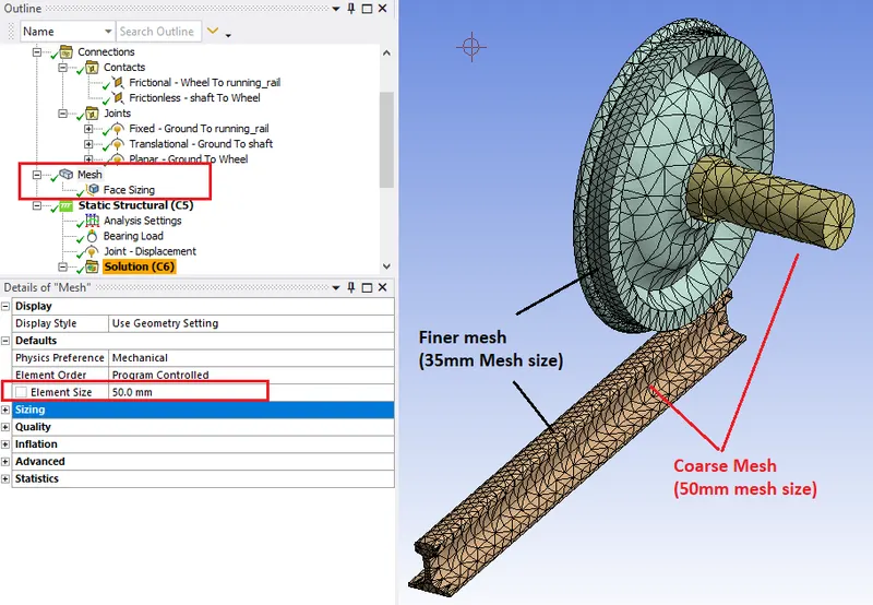
After that its type to deployed mesh over the geometry using mesh menu from the tree. The surfaces whose going to be in contact with each other has a mesh element size of 35mm and the other surfaces have a Mesh element size of 50mm.
Condition Set-up
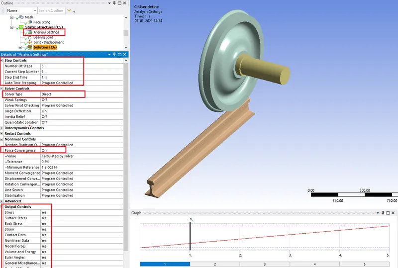
In the "Static-structural" Deck we have to set the boundary conditions, Analysis Settings.
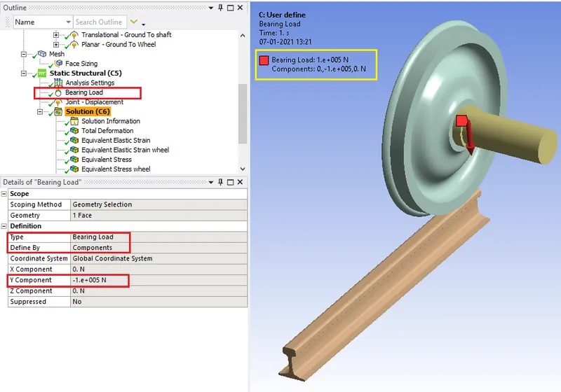
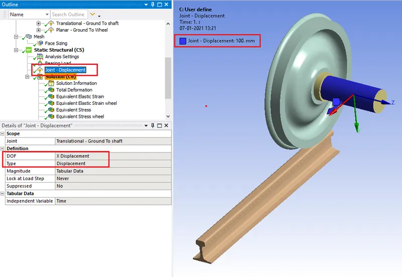
Output Requests
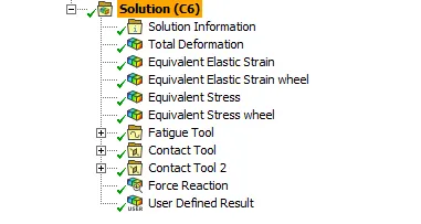
The Result evaluation

From the observation, we can say that as the Bearing load increases the Max stress and Strain inside the system also increases.
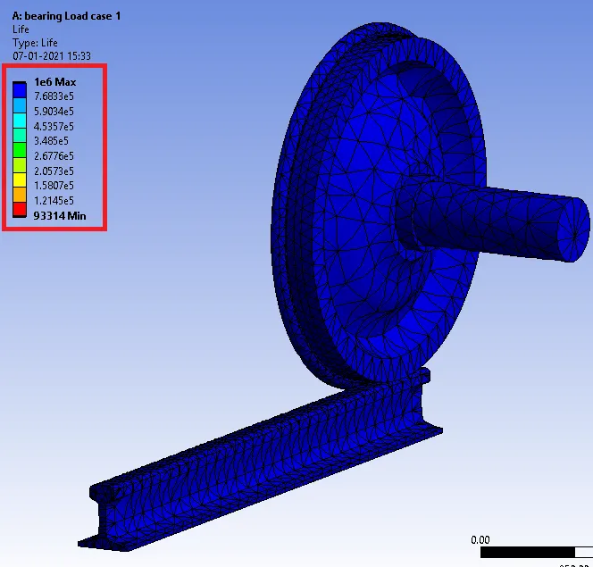
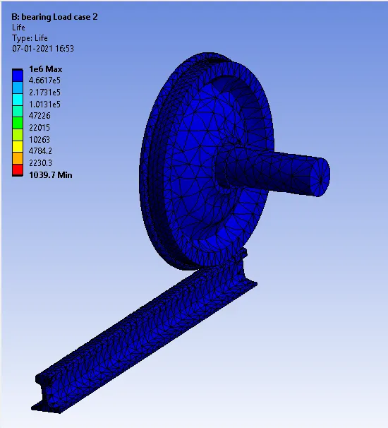
As the bearing load increases the life decreases to 1039.7 cyles from 93314 cycle
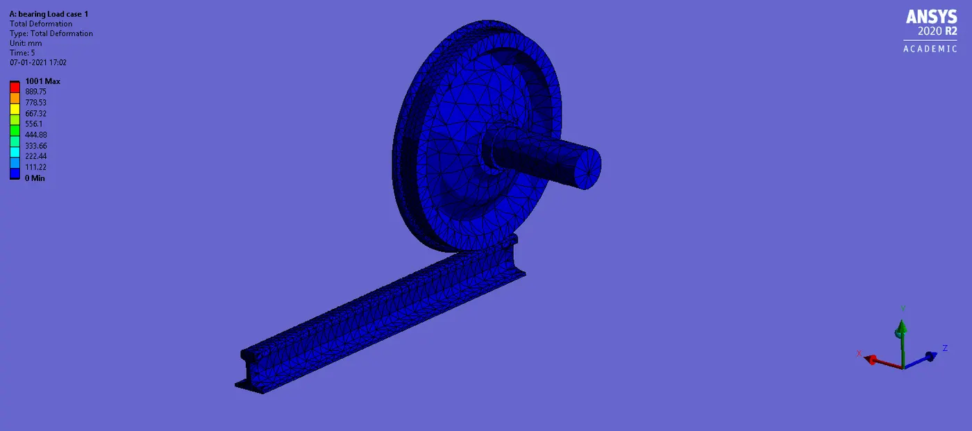
Total Deformation By Automated and User Define method
User-defined result in calculating total deformation
The total deformation is a scalar measure (i.e. magnitude) of the total displacement of the nodes in the meshed FE model. This total displacement of any node is a vector sum of its displacements in X, Y, and Z of the global coordinate system, and the magnitude of the vector just gives the total deformation of the particular node. Thus, to find the total displacement on the basis of user-defined results, we have to define some expression that represents the vector magnitude of all node displacement components.
Expression:- `sqrt((ux)^2 +(uy)^2 +(uz)^2`
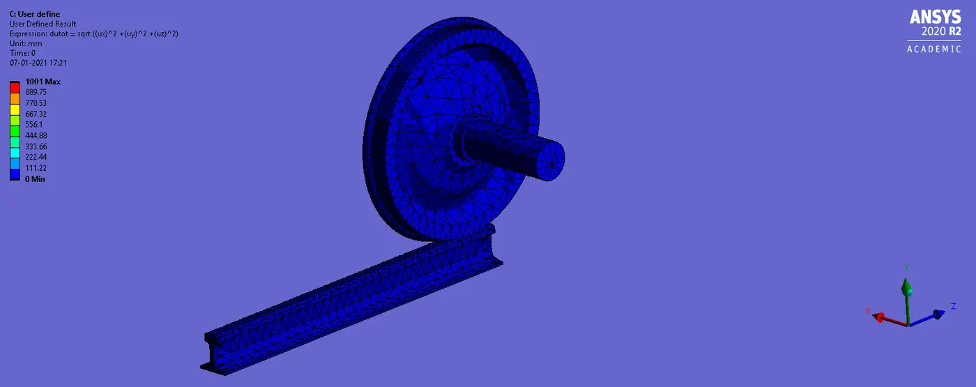
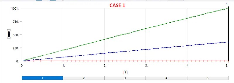
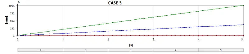
From the observation, we can say that the Total deformation by auto and user-defined methods are showing the same values for the total Deformation.