Week 2 Railwheel and Track
OBJECTIVE
Perform a static structural analysis on the Railwheel and Track setup and
Case 1: Multiply the bearing load by 5 times and compare the results with the load of 100000 N . Compare the Total Deformation, Equivalent stress under both the loads
Case 2: Implement a User defined result and calculate the Total Deformation from this result and check if it is the same as that obtained by the inbuilt result by ANSYS for a load of 100000 N.
CASE SETUP
In the ansys workbench , from the engineering sources add the Structural Steel material into the library.
Then we can insert the CAD model of the RailWheel and track and then we can assign structural steel on the to it.
Then in mechanical Modeller we can set up the contacts, here the contacts is required between wheel and shaft and also between wheel and track.
in contact region we set rename based on defiination and then in contacts we set with formulation as augmented langrange which is less sensitive to the stiffness of the conatct and have better convergance. And we set the contacts as frictional
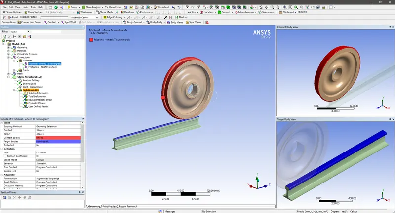
Contact Between Track and Wheel
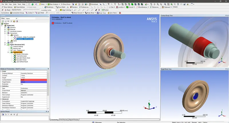
Contact Between Wheel and Shaft
First we need to fix the track since the wheel will be rolled on it.So using fixed support we can we can select the track faces and set the fixed support.
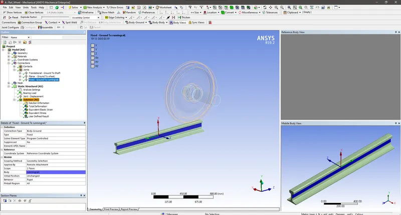
Fixed Support Creation
We need to create a planar joint to constrain the wheel in one fixed plane.So we create a Planar joint .
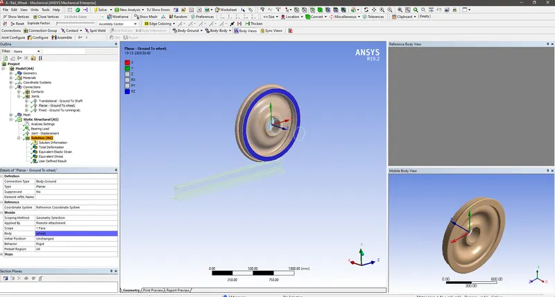
Planar Joint Creation
Then a translational Joint needs to be created on the shaft to impart motion along the linear axis to make the wheel rolls over the track.This can be done by creating the joint and chnage its type to tranlastional and select the shaft faces in its scope.
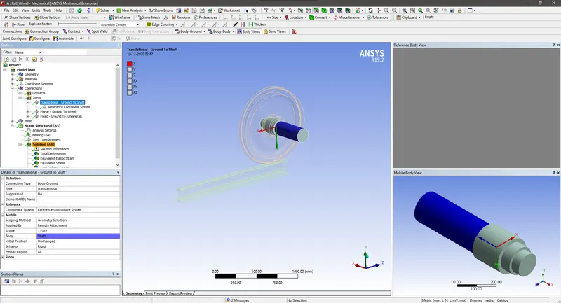
Translational Joint Created on Shaft
While meshing the CAD , we can mesh the whole model with 50 mm mesh and in the faces which is of higher importance like the faces which is in contact with track needs to be refined to 30 mm using the mesh face sizing , since those faces are important for the proper result.
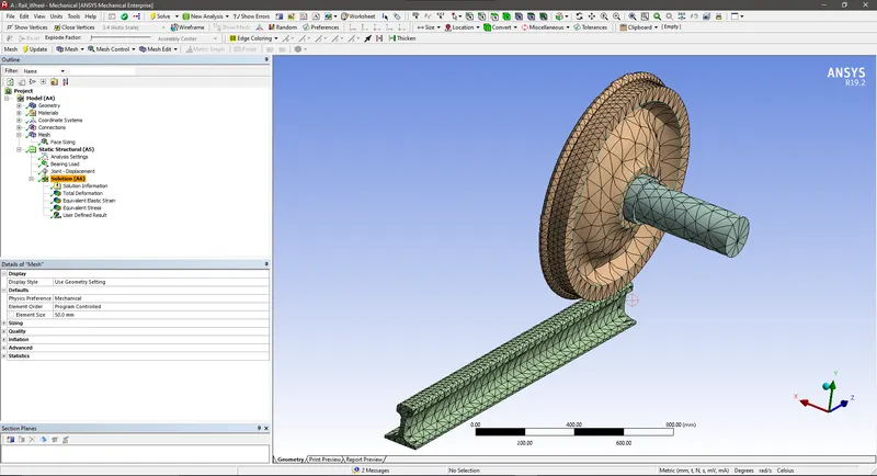
Face sizing Applied
Next is the setting up of the analysis settings .In that set steps as 6 and select all those steps and switch ON auto timestepping, Then define by time and set the intial time step,minimum time step and maximum timestep.Intial time step is made low so that the solver will run through first set of iteration without any errors as the possibility of the contacts happening in the model will be less.
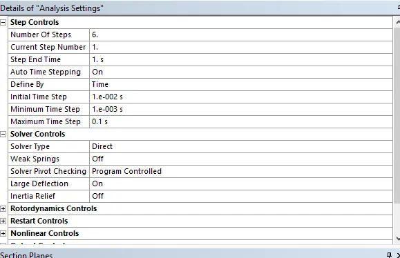
Analysis Settings
The joint load in the form of displacement in tabular form is applied to the shaft to impart the translational motion to the shaft.
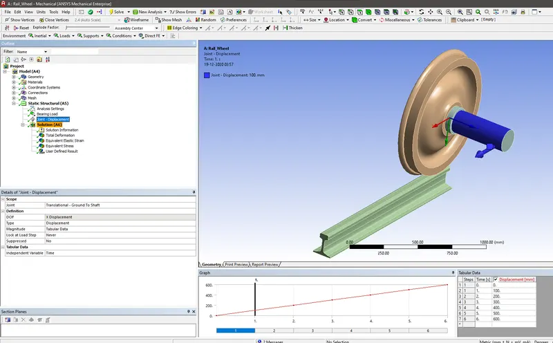
Displacement Applied in tabular Form to the Shaft
Then we needs to insert the Bearing load to the wheel face .This will be the carriage weight which will be acting downwards on the wheel face.In case1 we apply avbearing load of 100000 N force on it and as a case 2 we need to apply 500000 N as bearing load.
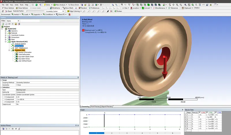
Bearing Load applied on the Wheel face
Then we can ask for the solution requests such as Total deformation , Equivalent Stress and Equivalent Strain.
RESULTS
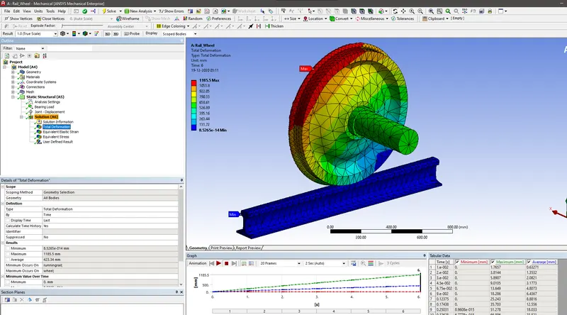
Total Deformation with Bearing Load of 100000N
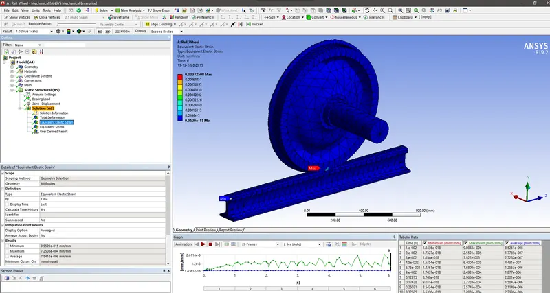
Equivalent Elastic Strain with the bearing load of 100000N
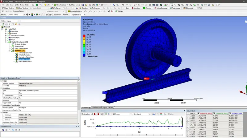
Equivalent Stress with Bearing Load of 100000N
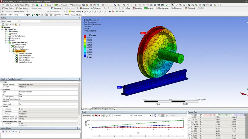
Total Deformation with Bearing Load of 500000N
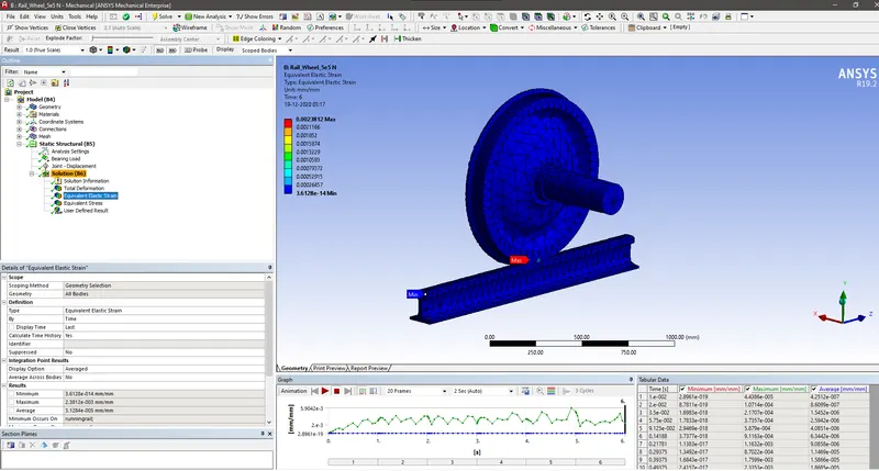
Equivalent Strain with Bearing Load of 500000N
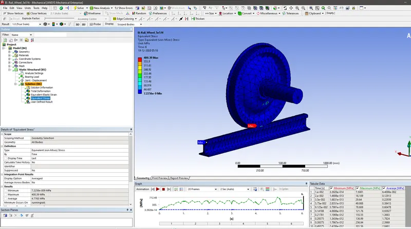
Equivalent Stress with Bearing Load of 500000 N
| Bearing Load | Total Deformation | Equivalent strain | Equivalent Stress |
| 100000 N | 1185.5 mm | 0.00072508 | 108.34 Mpa |
| 500000 N | 1123.6 mm | 0.0023812 | 400.39 Mpa |
As expected the increase in Bearing load leads to increase in Total deformation of the railwheel and the Equivalent Strain also increases thereby the equivalent Stress also increases.
In User defined result set the expression as sqrt(Ux^2+Uy^2+Uz^2) to get the total deformation as output.
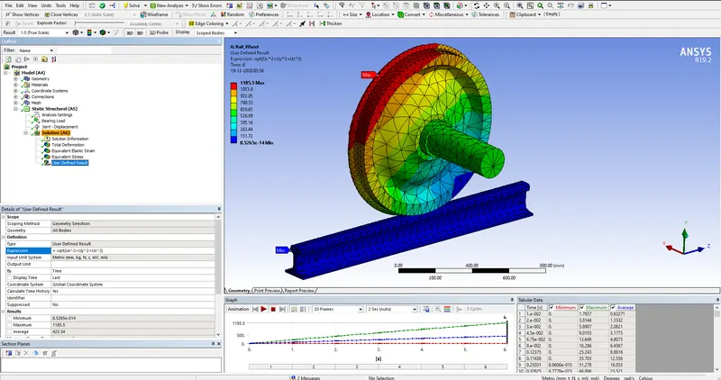
Total Deformation outputted using User Defined Result with Bearing Load of 100000 N
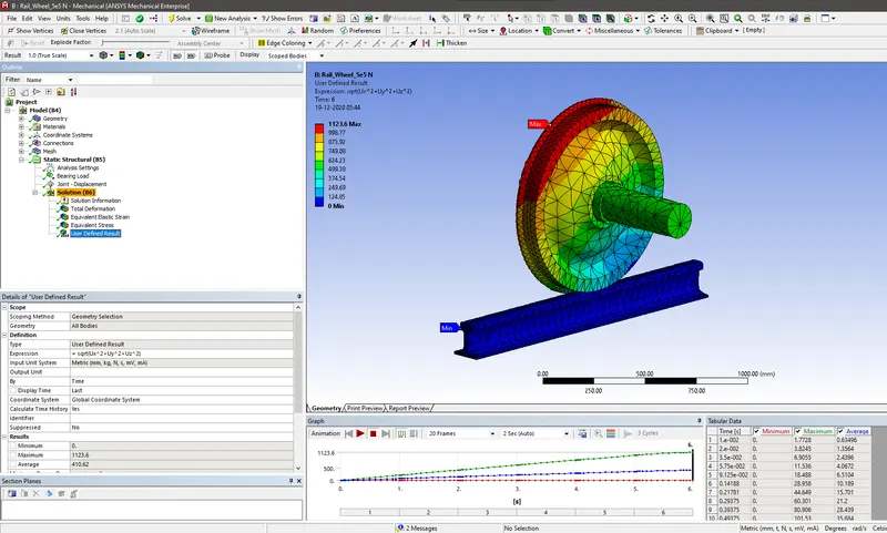
Total Deformation outputted using User Defined Result with Bearing Load of 500000 N
So we found out that total deformation value obtained using inbuilt result by ANSYS and the user defined output are same in both the cases.
CONCLUSION
So we found out that the User defined result request using the proper expression will outputs the exact results as we can obtained using the inbuilt ANSYS result.So we can ouputs the results what we want using the proper expression in addition to the other standard outputs.