Week 2 Railwheel and Track
AIM
To Perform a static structural analysis on the Railwheel and Track setup and evaluate results for total deformation, equivalent stress & life under loading condition.
Objective-
Our main objective is to perform analaysis as per below mentiioned case.
Case 1: Multiply the bearing load by 5 times and compare the results with the load of 100000 N (As done in week 2 video). Compare the Total Deformation, Equivalent stress, and the life under both the loads
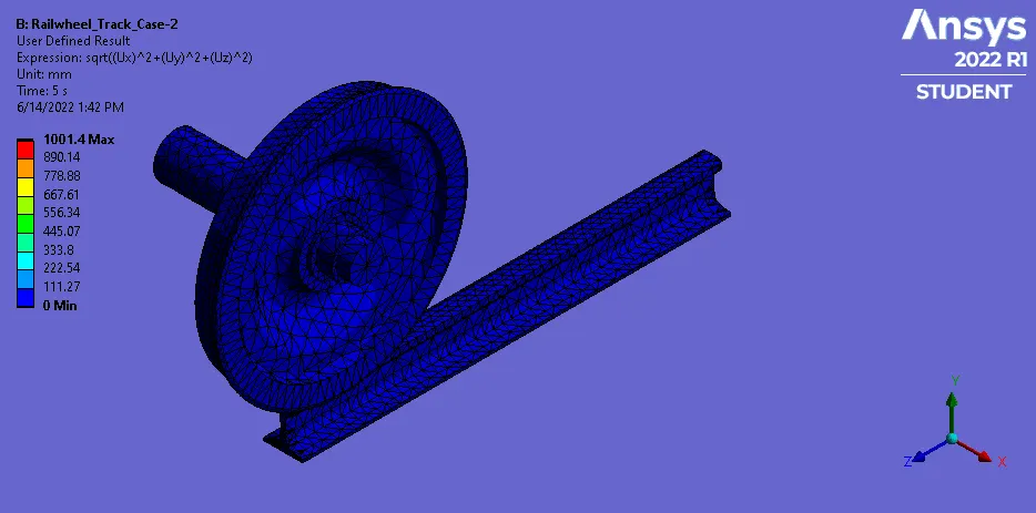
Case 2: Implement a User-defined result and calculate the Total Deformation from this result and check if it is the same as that obtained by the inbuilt result by ANSYS for a load of 100000 N.
Rail-Wheel Track-
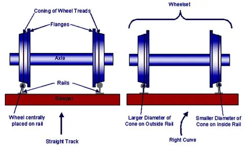
A train wheel or rail wheel is a type of wheel specially designed for use on railway tracks. The wheel acts as a rolling component, typically pushed onto an axle and mounted directly on a railway carriage or locomotive, or indirectly on a bogie (in the UK), also called a truck (in North America). The powered wheels under the locomotive are called driving wheels. Wheels are initially cast or forged and then heat-treated to have a specific hardness. New wheels are machined using a lathe to a standardized shape, called a profile, before being installed onto an axle. All wheel profiles are regularly checked to ensure proper interaction between the wheel and the rail. Incorrectly profiled wheels and worn wheels can increase rolling resistance, reduce energy efficiency and may even cause a derailment.
Procedure-
- We have to first start as new project in the ansys workbench and select the proper material for the rail wheel track.
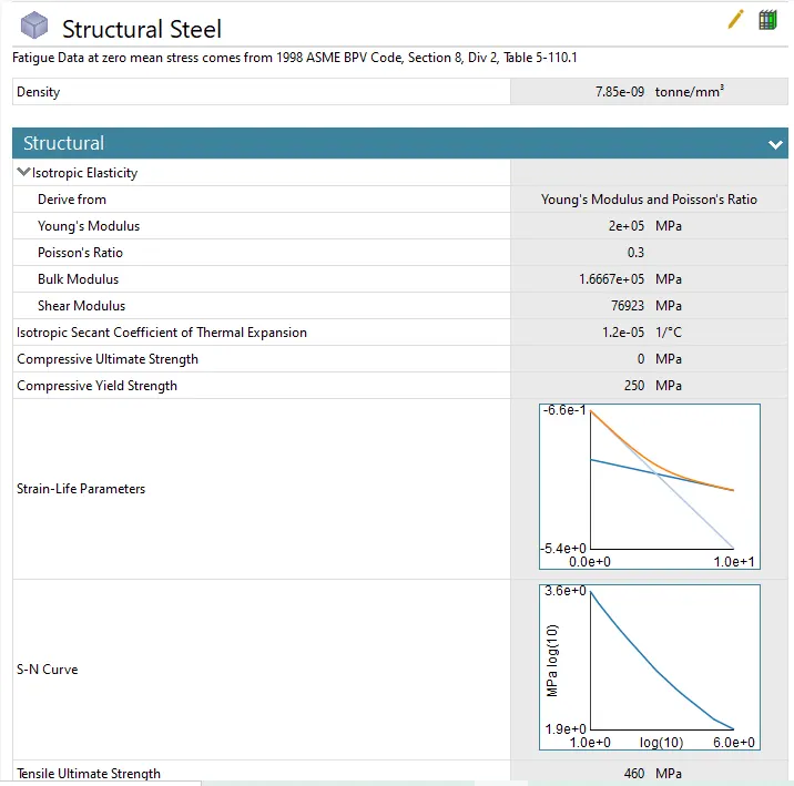
- Here no material has been specified in the project so we will select the structural steel as material.
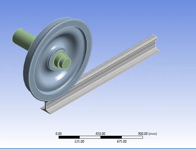
- Now we have to import the model for that right click on the geometry tab and hit import>>then select the file from saved location and hit ok.
Connections-
- Now we have to open mechanical model and the need to specify connections to railwheel track.
- We have to right click on the connection and then click on rename based on defination and again right click and flip the connections.
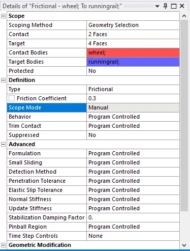
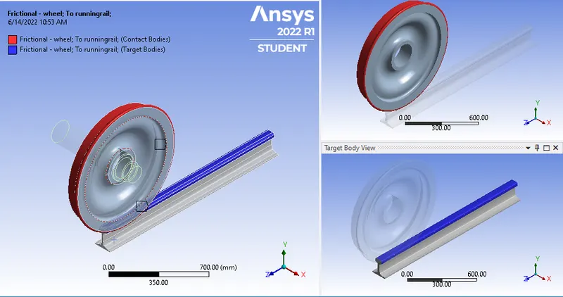
- First we will specify the connection between track and railwheel which is going to be frictional.
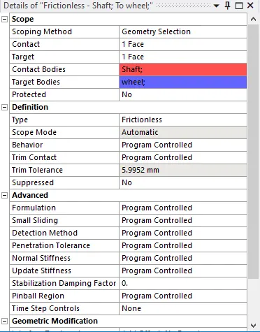
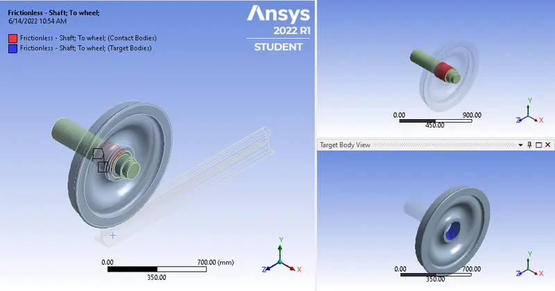
- Now we have to set the connection between railwheel and shaft which is going to be frictionless.
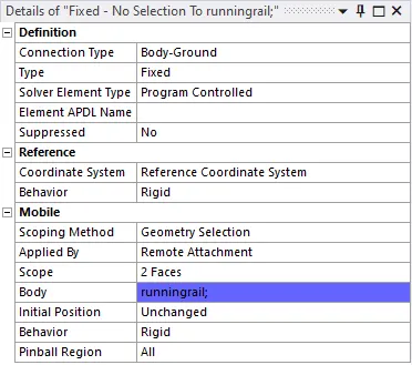
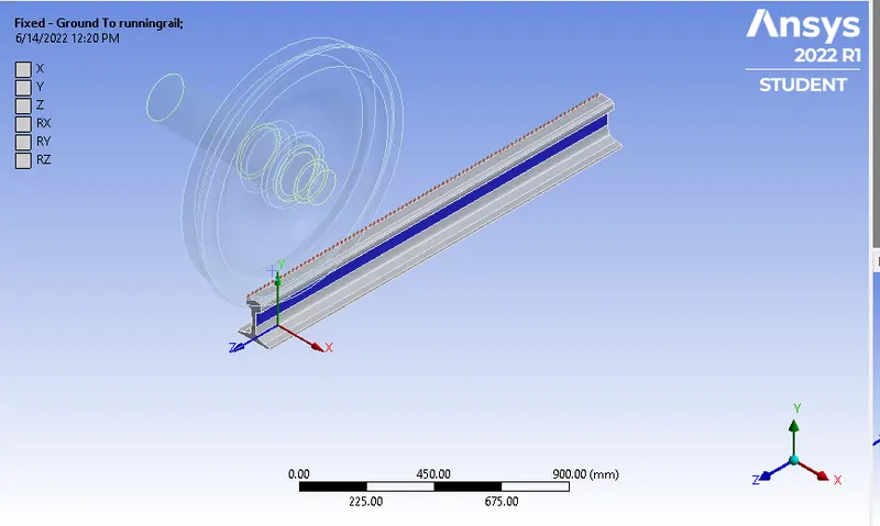
- Now we have to specify joints for all three parts, first we will start with the track which is going to be fixed type to ground joint.
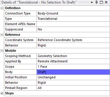
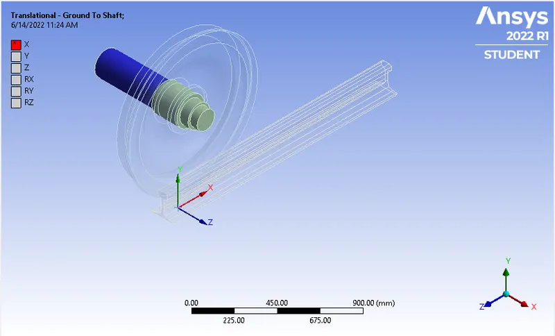
- Now for the shaft we are going to give translational joint, here we have to select X-axis a direction of rotation.
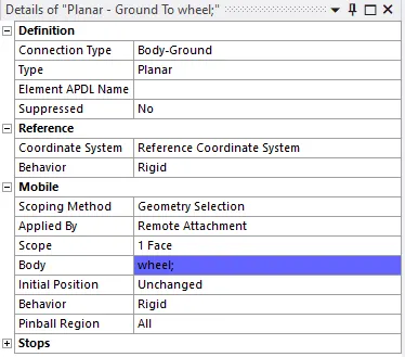
- Now for railwheel we have give planer joint.
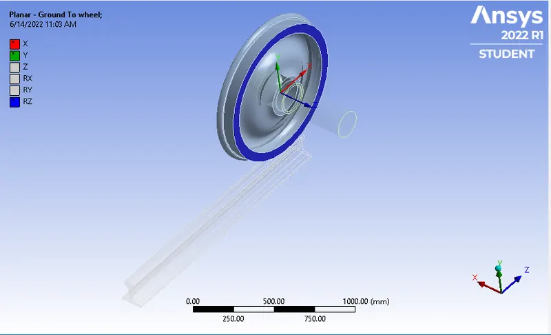
Mesh-
- Go to mesh then right click and the click on insert and select sizing.
- select size of 35mm as mesh size.
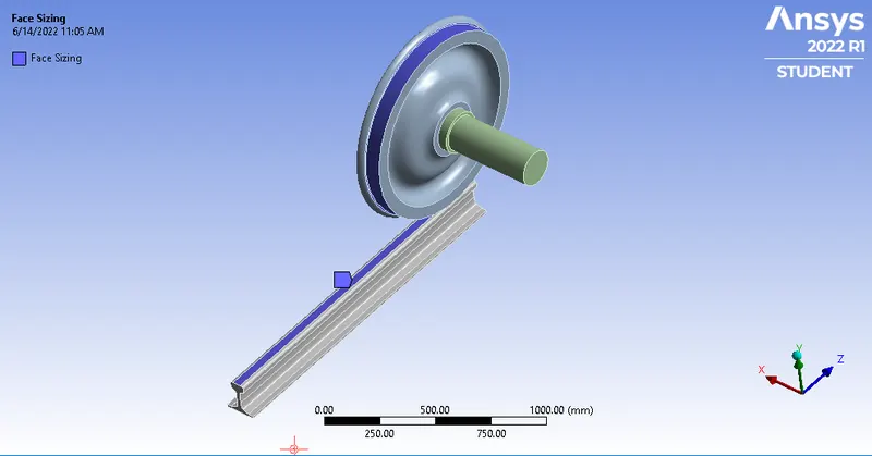
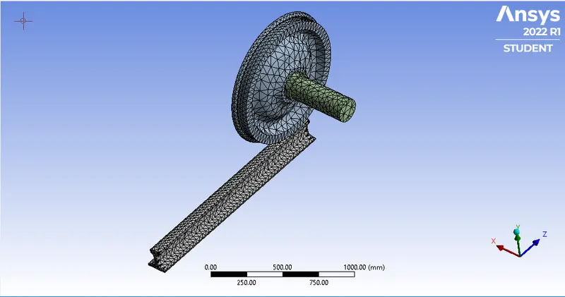
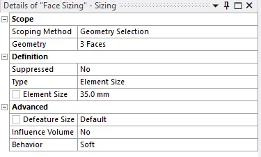
Analysis setting-
- Go to analysis setting and set number of set as 5 and refer below setting for 1st step.
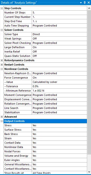
- Now for steps 2 to 5 refer below setups.
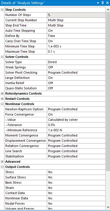
- Now we have to apply bearing load to inner diameter of railwheel, as show below of 100000N.
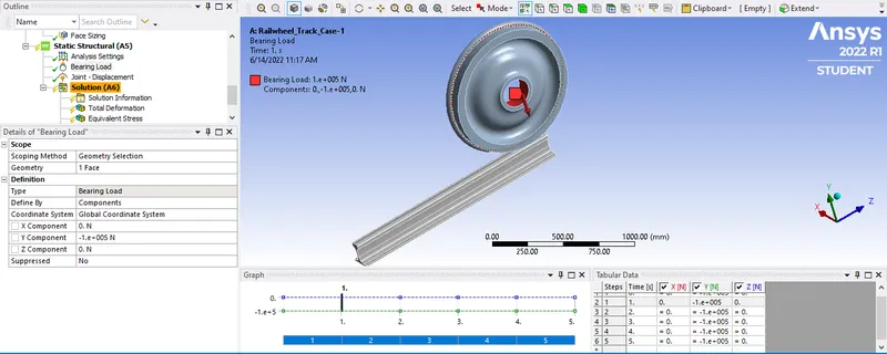
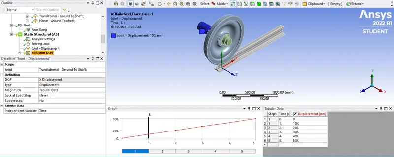
- After applying bearing load we have apply now joint loads for dispalcement.
- as we are going to roll it upto 500mm, so we select type as dispalcement and magnitude as tubular and on right side we input the data in it.
Solution-
- Here we have to define total deformation, to do so right click solution>>insert>>deformation>>total.
- Now for stress right click on the solution>>insert>>stresses>>equivalent (von-Mises).
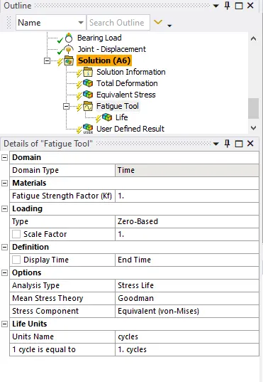
- Now for calulating life under stress we have to right click on the solution>>insert>>Fatigue>>fatigue tool>>in that we have to select Domain type time, type Zero based, analysis type stress and Mean stress theory as goodman.
- Then again right click on fatigue tool>>insert>>life.
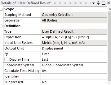
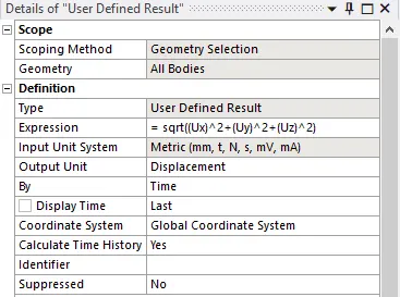
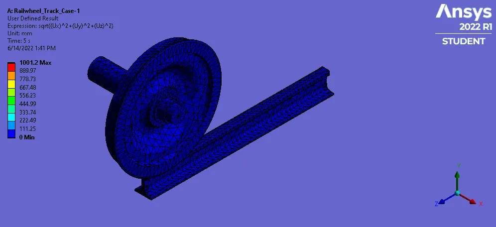
- Now for user defined solution, right click on solution>>insert>>user defined result and put values as per below.
- Right click on solution and hit solve.
Result-
Case-1-To evaluate the result for 500KN & 100KN and to compare both the results
100KN-
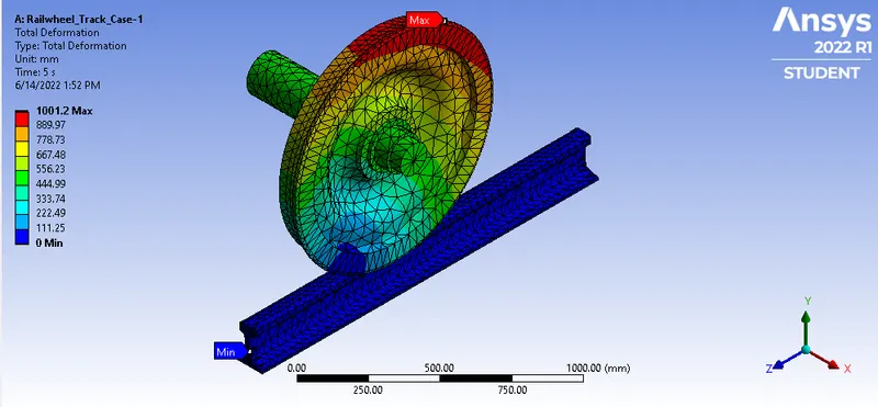
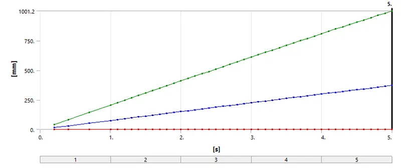
1. Total Deformation-
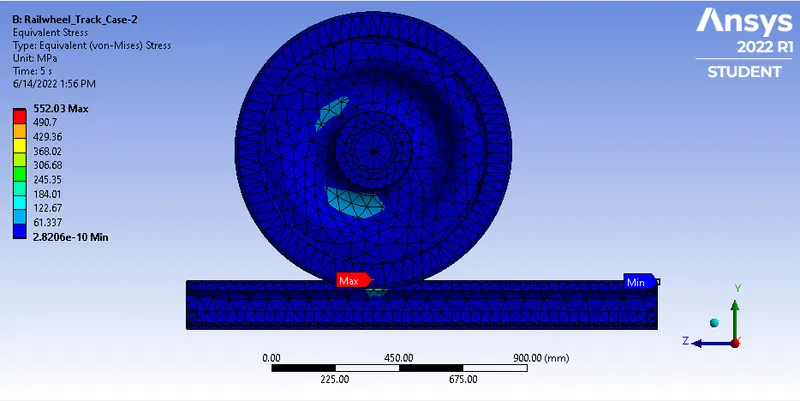
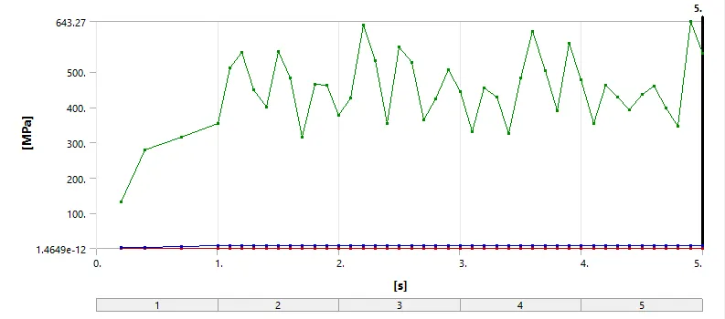
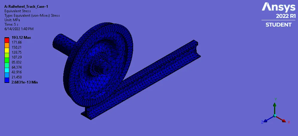
2.Equivalent Stress-
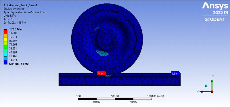
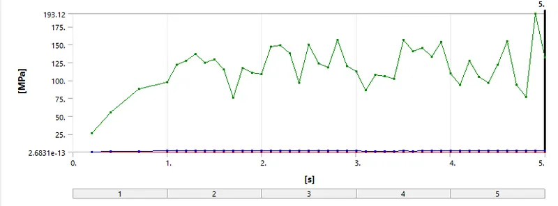
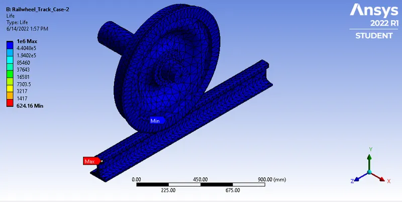
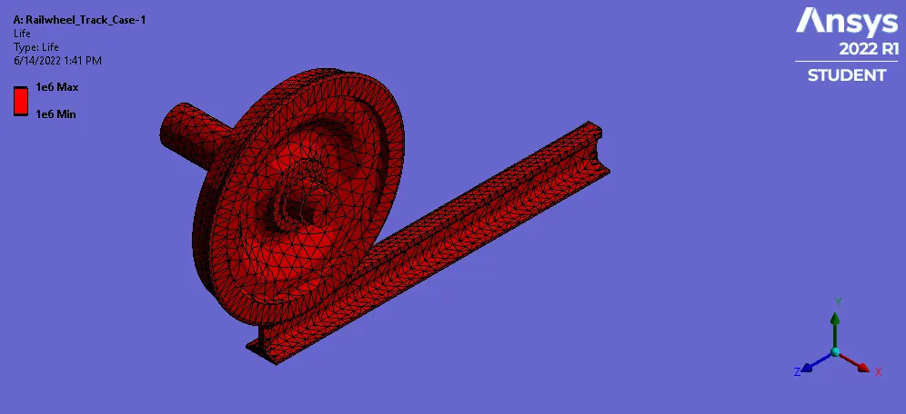
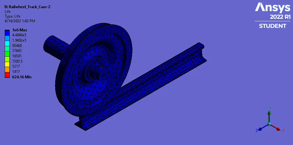
3. Fatigue Life Cycle-
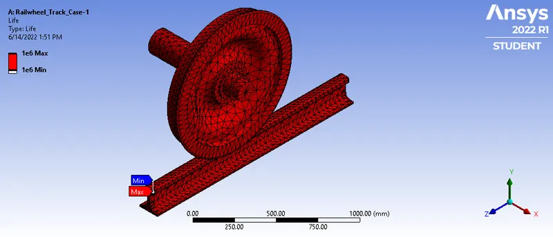
Bearing Load 500KN-
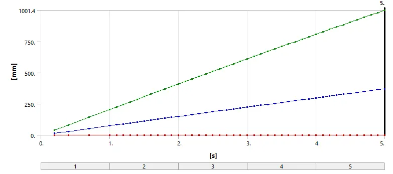
1. Total Deformation-
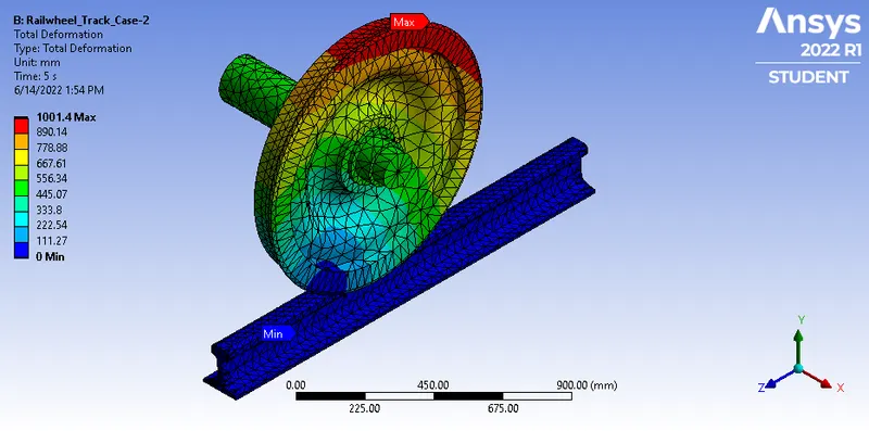
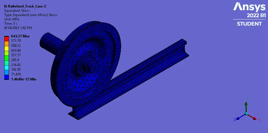
2.Equivalent Stress-
3. Fatigue life Cycle-
Result Comparison-
|
Solution |
Case-1-100KN |
Case-2-500KN |
||
|
Min. |
Max. |
Min. |
Max. |
|
|
Total Deformation (mm) |
0 |
1001.2 |
0 |
1001.4 |
|
Equivalent Stress (MPa) |
6.81E-11 |
132.6 |
2.82E-10 |
552.03 |
|
Fatigue Life |
1E6 |
1E6 |
642.16 |
1E6 |
From above Result we can say that the Total Deformation is nearly same but 500KN has highest stress. Though the min value of fatigue life is different but max. values are same. So for safety reasons we must avoid higher loads.
Case-2- Comparison of user defined result and Inbult result by ANSYS for 100KN load-
1. By Inbuilt Result
Total Deformation-
Now for user defined result we have considerd the formal as
Sqrt((Ux)^2+(Uy)^2+(Uz)^2))
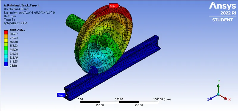
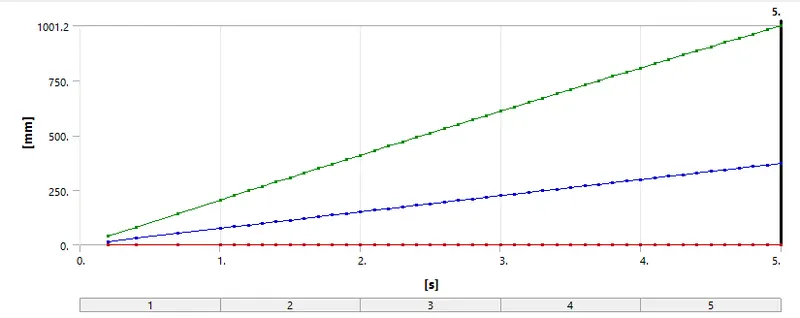
So from above result we can conclude that both the results are same.
Final Result Animations-
For Bearing Load of 100KN-
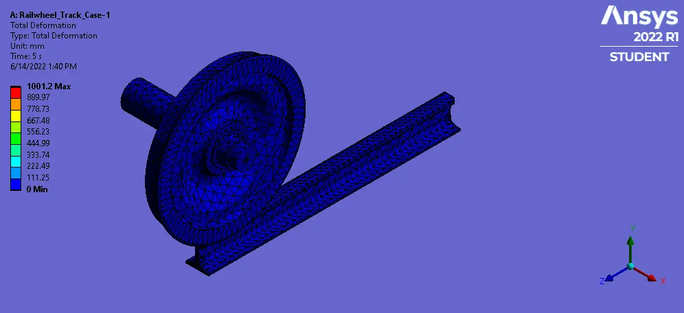
1.Total Deformation
2. Equivalent Stress-
3.Fatigue Life-
4. User Defined Result-
For Bearing Load of 500KN-
1. Total Deforamtion-

2. Equivalent Stress-
3. Fatigue Life-
4. User Defined Result-
Conclusion-
For the given railwheel track we have successfully carried the structural analysis by defining solutions for Total deformation, Equivalent Stress, Fatigue life and User Defined result for both 100KN & 500KN bearing loads. From result we have evaluated that by changing loads deformation result remains nearly same with huge difference in the equivalent stress values also the user desined result and inbuilt result for total deformation under 100KN bearing loads are same.