Week 2 - Flow over a Cylinder.
Flow over a Cylinder
Aim:
Simulate the flow over a cylinder and explain the phenomenon of Karman vortex street.
Objective:
PART-I
- Simulate the flow with the steady and unsteady case and calculate the Strouhal Number for Re= 100.
PART-II
- Calculate the coefficient of drag and lift over a cylinder by setting the Reynolds number to 10,100,1000,10000 & 100000. (Run with steady solver)
- Discuss the effect of Reynolds number on the coefficient of drag. [ Results should be validated with any standard literature and error should be within 5 %]
Flow over a cylinder
The flow over a cylinder is a classic problem in fluid mechanics that involves the study of the flow behavior around a circular cylinder in a uniform fluid stream. The problem is important in engineering applications such as the design of airfoils, heat exchangers, and offshore structures.
The flow over a cylinder problem can be analyzed using analytical, numerical, or experimental methods. Numerical simulations using computational fluid dynamics (CFD) software such as ANSYS Fluent are commonly used to model the flow behavior around a cylinder. These simulations can provide detailed information about the flow field, such as velocity and pressure distributions, and can be used to predict the occurrence of vortex shedding and other flow phenomena.
The flow over a cylinder problem is an important benchmark problem in fluid mechanics and is used to validate CFD models and experimental techniques. It is also an important problem in the design of various engineering structures, where the occurrence of vortex shedding can lead to undesirable flow-induced vibrations and structural failures.
Reynold’s number
The flow over a cylinder problem is typically characterized by a number of parameters, including the Reynolds number (Re), the diameter of the cylinder (D), the velocity of the fluid stream (U), and the viscosity of the fluid (μ). The Reynolds number is defined as the ratio of inertial forces to viscous forces in the fluid and is given by:
Re = ρUD/μ
where ρ is the density of the fluid.
At low Reynolds numbers, the flow around the cylinder is steady and laminar, with no vortex shedding. As the Reynolds number increases, the flow becomes more complex and unsteady, and vortices start to shed from the cylinder. This phenomenon is known as the Karman vortex street and is characterized by the shedding of vortices alternately on either side of the cylinder, resulting in a characteristic pattern of vortices in the wake of the cylinder.
Karman vortex street
Karman vortex street is a phenomenon that occurs in the flow around a bluff body, such as a circular cylinder, when the Reynolds number is high enough. It is characterized by the shedding of vortices alternately on either side of the body, resulting in a distinctive pattern of vortices in the wake of the body. The phenomenon was first observed and studied by the Hungarian physicist Theodore von Karman in the early 20th century.
The flow around a cylinder at high Reynolds numbers is initially steady and laminar. As the velocity of the flow increases, the boundary layer becomes thinner and eventually separates from the surface of the cylinder, resulting in the formation of vortices in the wake of the cylinder. These vortices are formed by the instability of the shear layer that separates from the cylinder and interacts with the downstream flow. The vortices are shed alternately from each side of the cylinder, with each vortex pair having opposite circulation and rotating in opposite directions.
The shedding of the vortices creates a fluctuating pressure distribution on the surface of the cylinder, which can cause the cylinder to vibrate or oscillate. This can be a concern in engineering applications where the vortex shedding frequency can match the natural frequency of the structure, leading to resonance and potential structural failure.
Application of Karman vortex street
The occurrence of Karman vortex street is important in various engineering applications, such as the design of airfoils, heat exchangers, and offshore structures. Understanding the phenomenon and its effects on flow behavior is crucial for predicting the performance and reliability of these structures. The phenomenon has also been used in flow control applications, where the shedding of vortices can be manipulated to control the flow behavior around a body.
Strouhal number
The Strouhal number is a dimensionless quantity that characterizes the unsteady flow behavior around a bluff body. It is defined as the ratio of the frequency of vortex shedding to the product of the characteristic length of the body and the velocity of the flow. The Strouhal number is expressed as:
St = f * D / V
where St is the Strouhal number, f is the frequency of vortex shedding, D is the diameter of the circular cylinder, and V is the velocity of the flow.
The significance of the Strouhal number lies in the fact that it provides a measure of the unsteadiness of the flow around a bluff body. The Strouhal number is a non-dimensional quantity, which means that it is independent of the size or speed of the body or the fluid. This makes it a convenient parameter to use for comparing the unsteady flow behavior of different bodies and in different flow conditions.
The Strouhal number is widely used in fluid mechanics and aerodynamics to predict the occurrence of vortex shedding and to design and optimize various flow devices. It is particularly important in the design of structures that are susceptible to flow-induced vibrations, such as bridges and tall buildings. By adjusting the shape and dimensions of the body to achieve a specific Strouhal number, designers can reduce the risk of structural failure due to vortex shedding.
The Strouhal number is also used in the field of fluid flow measurement. By measuring the frequency of vortex shedding using sensors or flow visualization techniques, the flow rate or velocity of the fluid can be calculated accurately.
Methodology:
To simulate the flow over a cylinder, we first created a 2D model of a cylinder using Ansys discovery and Spaceclaim. The dimensions of the cylinder and boundary are as follows.
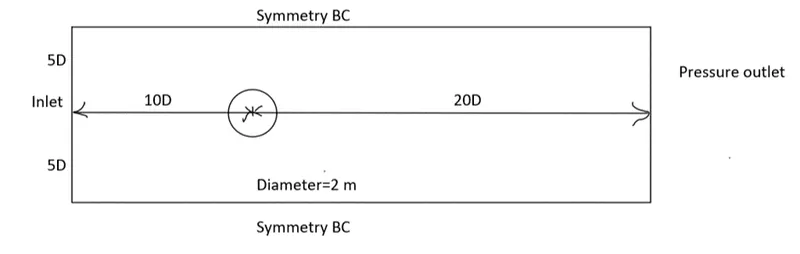
We created a mesh using the Ansys Fluent meshing tool, with a focus on ensuring that the mesh is fine enough to accurately capture the vortices shedding from the cylinder. Also created inflation layer around the cylinder.
The model was then imported into Ansys Fluent for further analysis. We then set up the boundary conditions, specifying the inlet velocity, and the cylinder as a no-slip wall. We also specified the pressure outlet boundary condition. Created monitor point from the cylinder to capture the velocity and vortex shedding at that point.
PART-1
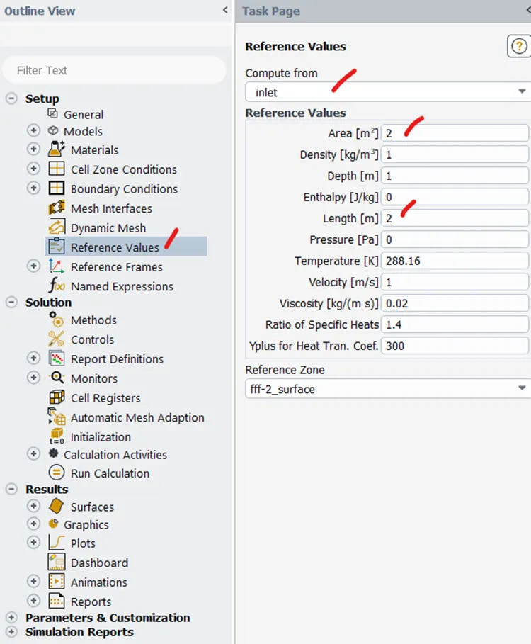
Steady state, Re=100, μ=0.02 kg/(m.s), ρ=1 kg/m^3, d=2 m, velocity=1 m/s
Geometry
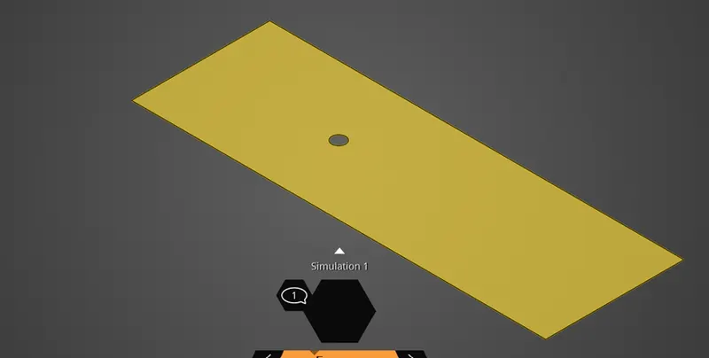
Mesh
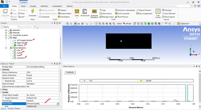
All triangles Method used for Meshing, size 0.25 m, edge sizing given around the cylinder with number of edges 36 with inflation layer 5.
Setup
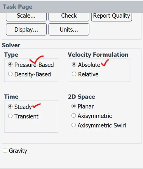
Laminar flow
Material – User Material
μ=0.02 kg/(m.s),
ρ=1 kg/m^3,
Boundaries
inlet velocity=1 m/s
outlet, gauge pressure =0
Wall - Stationary wall and No slip condition
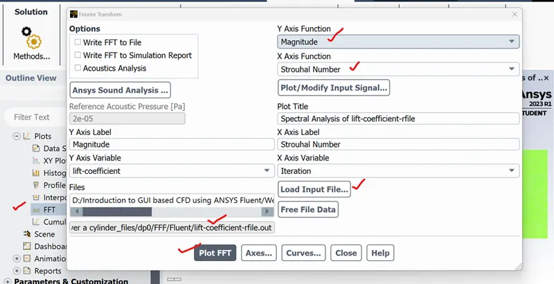
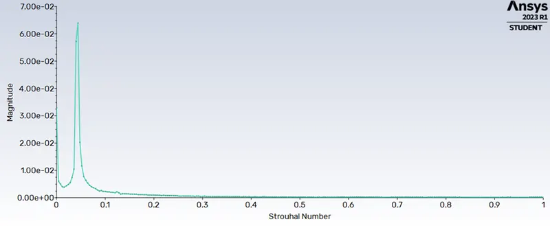
To calculate Strouhal number
Reference Values
Steady state
Re=100, inlet velocity = 1 m/s
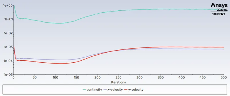
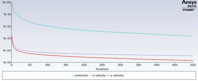
Scaled Residuals
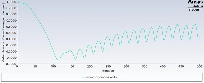
Monitor-point Velocity
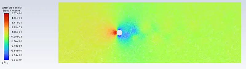
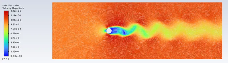
Monitor point Velocity = 0.4330 m/s
Pressure contour
Velocity contour
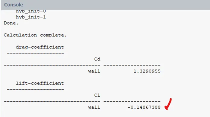
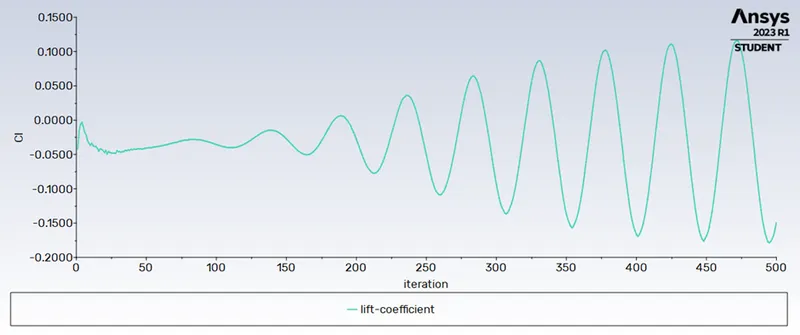
Coefficient of Lift
Solutions --> Report Definitions --> Lift coefficient --> Right Click --> compute
CL = 0.1487
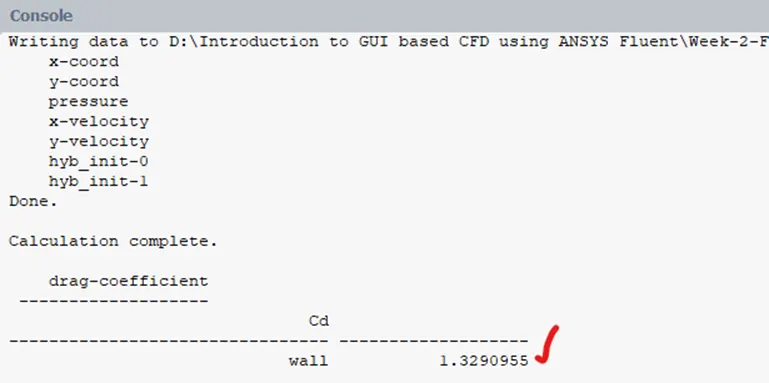
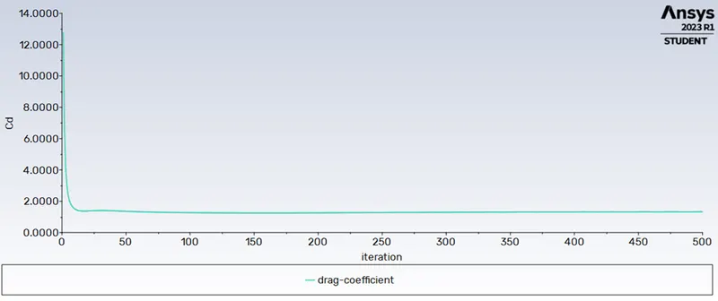
Coefficient of Drag
Solutions --> Report Definitions --> Drag coefficient --> Right Click --> compute
CD = 1.3291
Strouhal Number
Strouhal Number = 0.044
Steady state
Re=10, inlet velocity = 0.1 m/s
Scaled Residuals
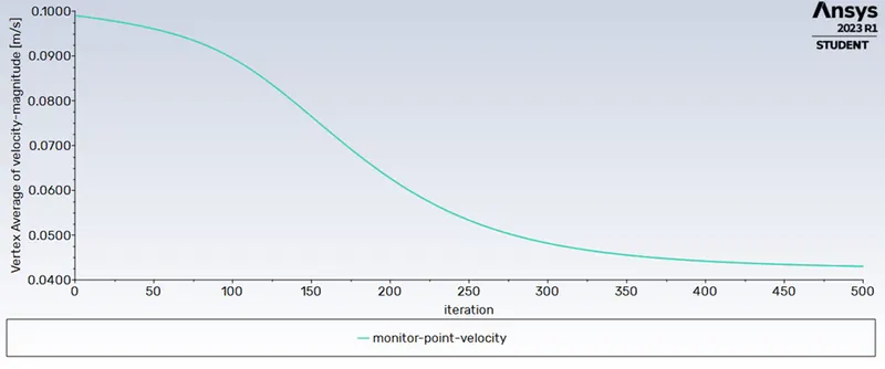
Monitor-point Velocity
Monitor point Velocity = 0.0430 m/s
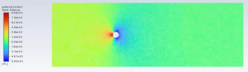
Pressure contour
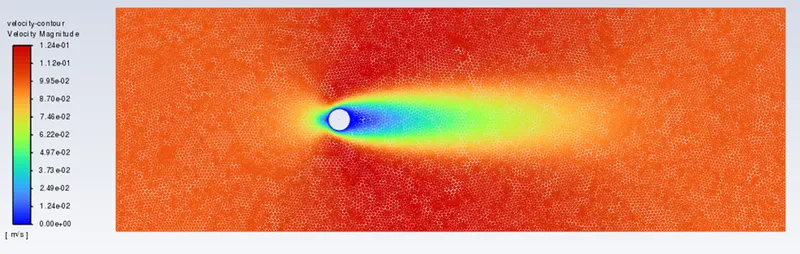
Velocity contour
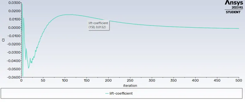
Coefficient of Lift
CL = 0.0011686803
Coefficient of Drag
CD = 3.326893
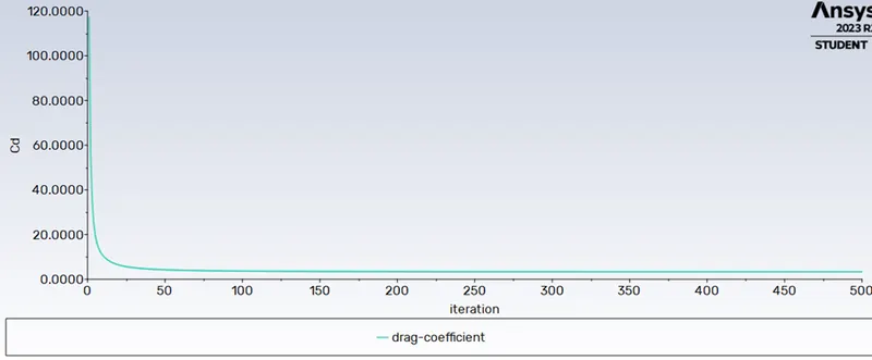
Re=1000, inlet velocity = 10 m/s
Scaled Residuals
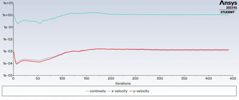
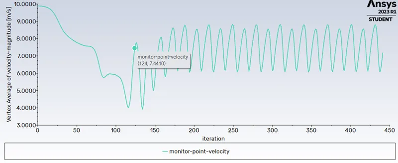
Monitor-point Velocity
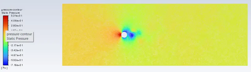
Pressure contour
Velocity contour
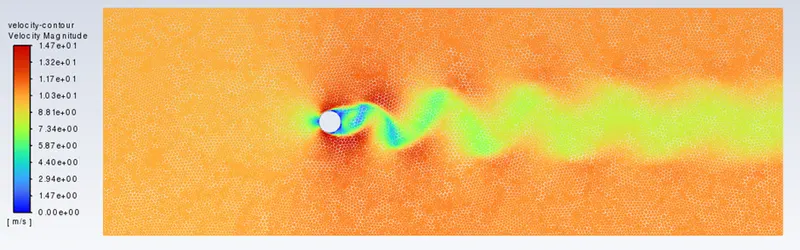
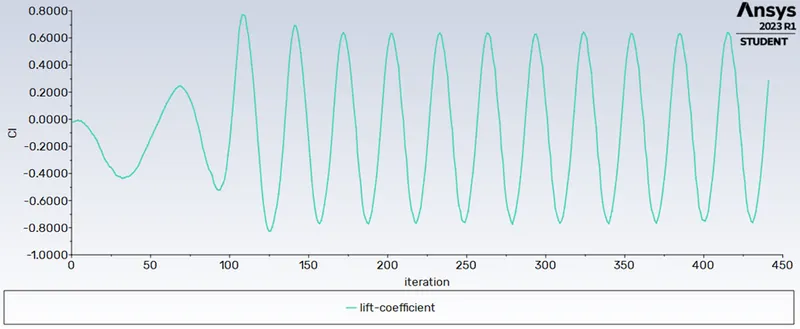
Coefficient of Lift
CL = 0.28461268
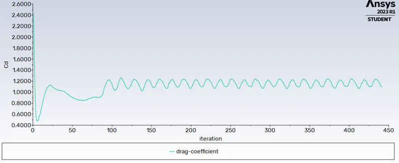
Coefficient of Drag
CD = 1.0911287
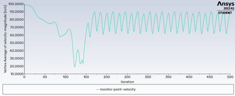
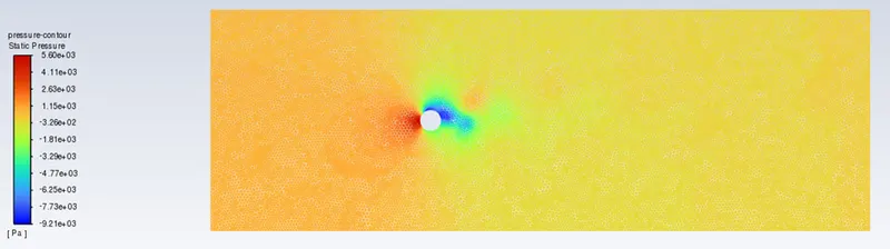
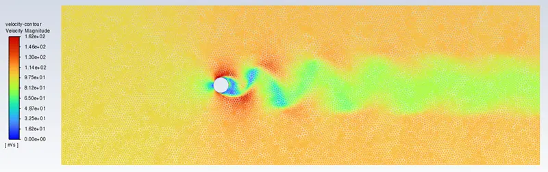
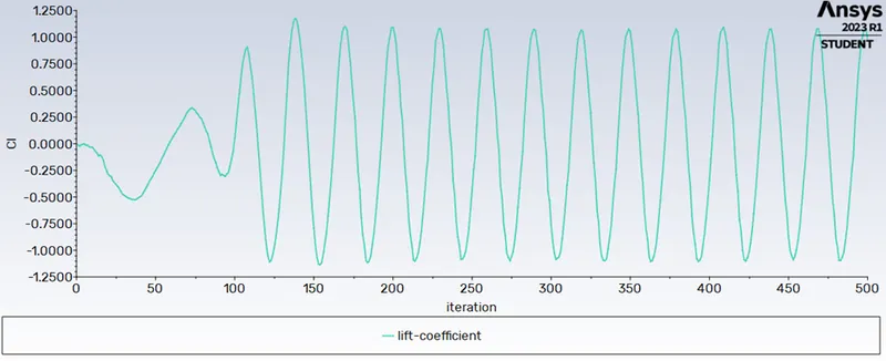
Re=10000, inlet velocity = 100 m/s
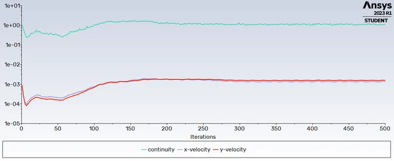
Scaled Residuals
Monitor-point Velocity
Monitor point Velocity = 87.0292 m/s
Pressure contour
Velocity contour
Coefficient of Lift
CL = 0.9838
Coefficient of Drag
CD = 1.3272
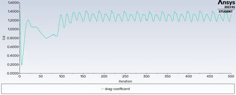
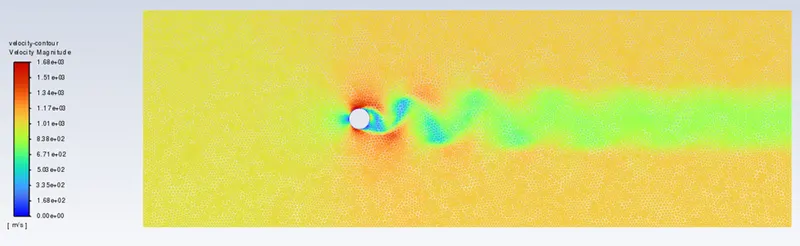
Re=100000, inlet velocity = 1000 m/s
Scaled Residuals
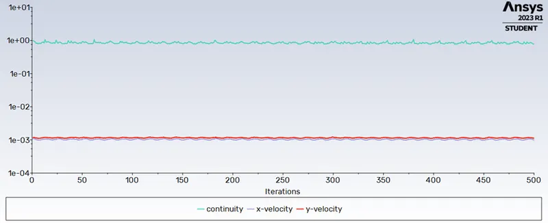
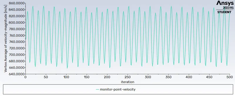
Monitor-point Velocity
Monitor point Velocity = 833.2942 m/s
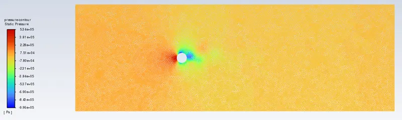
Pressure contour
Velocity contour
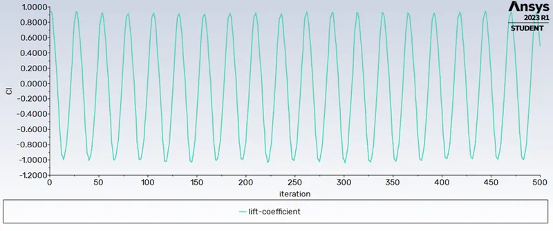
Coefficient of Lift
CL = 0.4875
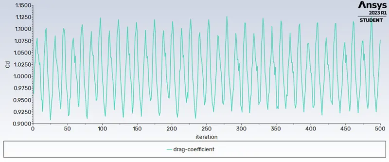
Coefficient of Drag
CD = 1.0767
Result
|
Case 1: Re=100 |
|
|
Strouhal Number |
|
|
Steady state |
0.044 |
|
Case 2: Steady State |
||
|
CL |
CD |
|
|
Re=10 |
0.0012 |
3.3268 |
|
Re=100 |
0.1487 |
1.3291 |
|
Re=1000 |
0.2846 |
1.0911 |
|
Re=10000 |
0.9838 |
1.3272 |
|
Re=100000 |
0.4875 |
1.0767 |
For Re= 10, the flow becomes unsteady and the wake behind the cylinder becomes asymmetric. Vortices are shed alternately from each side of the cylinder, resulting in a fluctuating pressure distribution and an increase in the coefficient of drag.
While increasing the Reynolds number the drag coefficient starts to decrease. This sudden drop in CD is called the “drag crisis”, which is associated with the separation of the boundary layer from the surface of the sphere.
In summary, the Reynolds number has a significant effect on the coefficient of drag for the flow over a cylinder. At low Reynolds numbers, the coefficient of drag is relatively low and is governed by the viscous forces, while at higher Reynolds numbers, the wake behind the cylinder becomes asymmetric and vortices are shed, resulting in an increase in the coefficient of drag. At very high Reynolds numbers, the flow becomes turbulent and the coefficient of drag reaches a maximum value before starting to decrease due to the effects of turbulence
References
https://www.sciencedirect.com/science/article/pii/S0307904X08000243