Week 2 - Flow over a Cylinder.
Simulate the flow over a cylinder and explain the phenomenon of Karman vortex street
AIM: To simulate the flow over a cylinder and explain the phenomenon of Karman vortex street
Introduction:
Before going to the experiment some basic fundamental need to know are:
Drag and Lift
Drag is the force experienced by an object representing the resistance to its movement through a fluid. Sometimes called wind resistance or fluid resistance
Lift is directed perpendicular to the flight path
Equations of lift and drag are written as,
Drag = 0.5*Coefficient of Drag (Cd)* density * Velocity^2*Area
Lift=0.5*Coefficient of lift (Cl)*Velocity^2*Area*Density
Boundary layer Theory:
Whenever a fluid flows over a body due to the cohesive forces the fluid velocity becomes zero with respective to the body. In the direction normal to the body the velocity gradually increases to equal to the free stream velocity this region where velocity less than free stream velocity is called boundary layer region. This theory is important to learn for dynamics of viscous fluid flows and heat transfer.
Boundary layers may be either laminar, or turbulent depending on the value of the Reynolds number.
The Reynolds number is the ratio of inertia forces to viscous forces and is a convenient parameter for predicting if a flow condition will be laminar or turbulent. It is defined as
Where, Re= Reynolds number (non-dimensional)
ρ= Density of fluid (kg/m3)
µ= dynamics Viscosity of fluid (kg/ms)
v= Velocity of Fluid (m/s)
D= Characteristic length, D=Length of flat surface/Diameter of a pipe (meters).
Flow separation: flow separation is the detachment of a boundary layer from a surface into a wake.
As the Reynolds number increases more the flow separation form surface takes place at small distances from the end of point of contact.
In fluid dynamics, a Kármán vortex street (or a von Kármán vortex street) is a repeating pattern of swirling vortices, caused by a process known as vortex shedding, which is responsible for the unsteady separation of flow of a fluid around blunt bodies.
Solving and Modelling Approach
- As the fluid passes over the surface of a solid body, to know the exact variations of pressure and velocities at the surface, Inflation layers are used while meshing.
- To define the inflation, 3 things are must, size of first layer (calculated from Y+ equations), Growth rate (1.1-1.3) and total height of inflation layer (mostly equals to boundary layer thickness)
- In place of varying the Reynolds number, lets change velocities by calculating for different Reynolds number (10,100,1000,10000,100000).
- To run one the simulation in transient as well as in steady state mode. For transient, time steps are needed.
- Convergence might not possible in all the cases, so repeatability is takes a factor to stop the iterations.
Procedure
Pre-processing:
- We have designed using space claim in the work bench. With a circle at middle and boundaries (as a rectangle) at respective distances, as shown below.
- If circle diameter is D, then length of front portion is 10D, sides 5D, and rare 20D. here, D= 2meters.
- Then meshing is done by introducing inflation layers, by maintaining good volume transition. As near the walls the viscous effect is more, smaller size of mesh elements is more suitable, and away inertial forces dominates, so some larger elements are suitable. Growth rate of 1.1-1.3 is given. As shown in below figure.
- Then name the sections: inlet and outlet
- Try to adjust the mesh sizes as close as possible, for student version up to 50000 elements can only be simulated.
Setup and Solving
- Firstly, for steady state select steady and for unsteady select transient model
- Then define the material. Lets consider a new user defined material, add it by copying from the existed material and rename and edit the propertiesà density 1 Kg/m3 and viscousity 0.05 Kg/ms
- Then in the physics choose laminar solver as a viscous model.
- In the method of solving choose SIMPLE.
- Define the boundary condition, for inlet vary the inlet velocity for each case based in reynolds number.
RE=denisity*velocity*characteristic length/dynamic viscosity.
- Before defining the report give the reference, in the reference check the area and length. Change those to characterstic length of 2 meters and area of 2*1 m^2.
- Create the point, to study the variation of velocity near to the cylinder. (at 8mm right to the cylinder)
- Define the reoprt of drag coefficient and lift coefficient in solution tab.
- Give intiallization count of 10.
- Then, select the contur of velocity and pressure.
- Now run for the n no of iteration untill the solutions get converged.
Results
Table 1 Coefficient of Drag and Coefficient of lifts Vs Velocity
|
Velocity |
Coefficient of Drag |
Coefficient of Lift |
|
0.25 |
4.6025 |
-.003757 |
|
2.5 |
152.58 |
-5.0087 |
|
25 |
12089.89 |
-1722.45 |
|
250 |
1358201.2 |
-426149.1 |
|
2500 |
1.2140979e+08 |
1.1862443e+8 |
Simulation of Steady and Unsteady flow
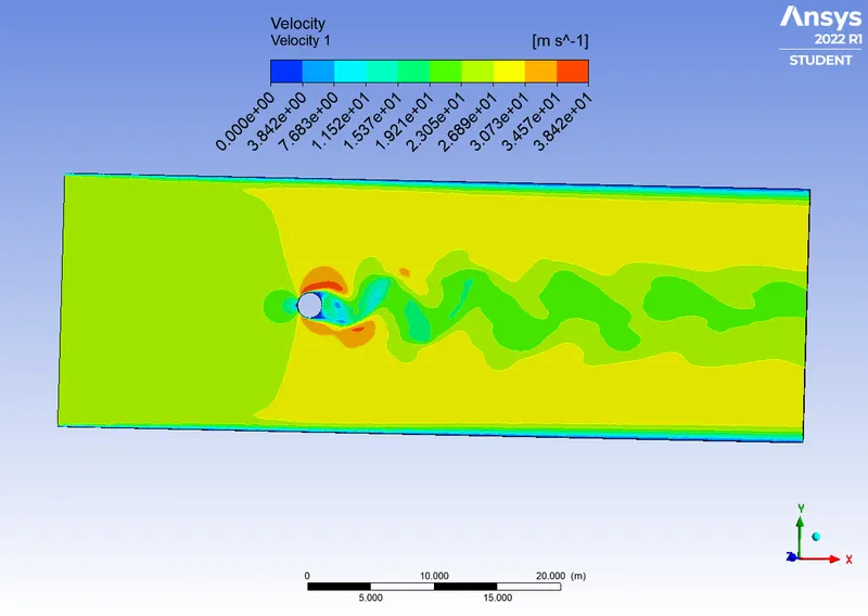
For the Reynolds number of 100, the simulation of performed for both steady and transient. And calculated the Strouhal Number.
Steady 0.006681
Transient 0.000155
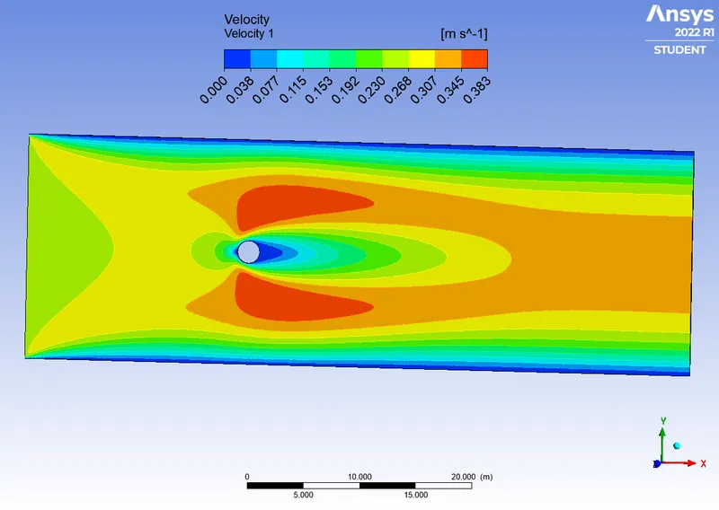
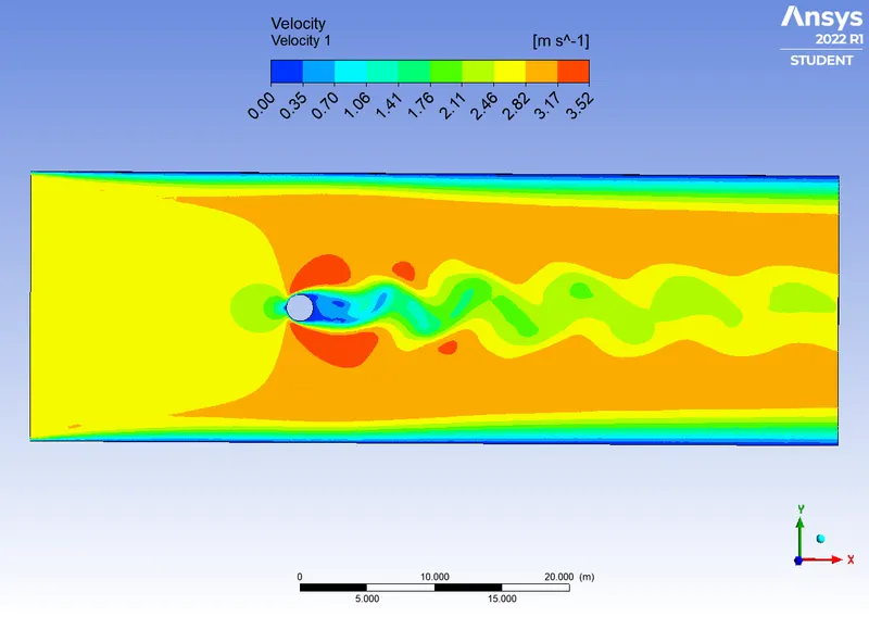
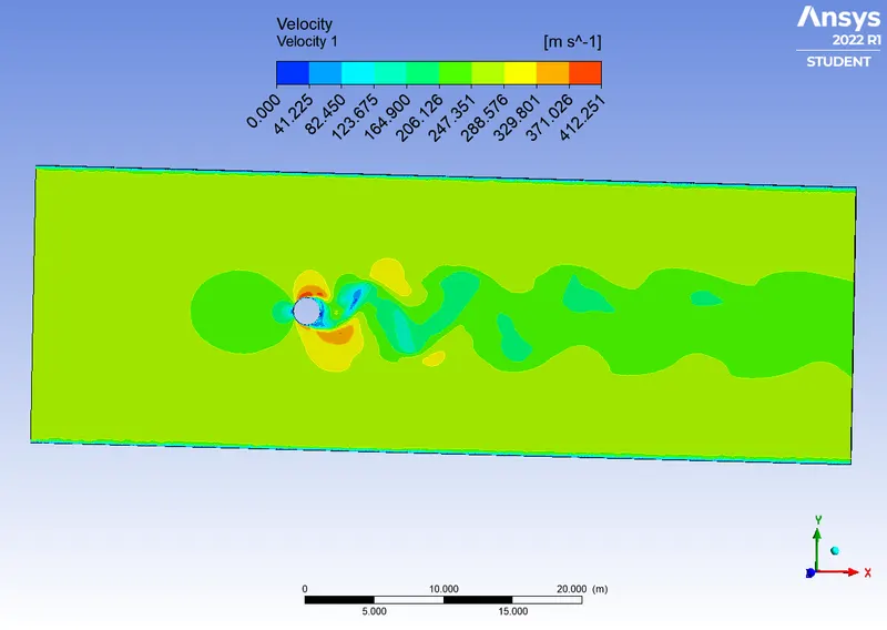
Results: coefficient drag, coefficient of lift, Pressure contour, Velocity contour, and Average velocity are following images provided below at different Reynolds number
For Reynold number = 10
For Reynolds number = 100
For Reynold number = 1000
For Reynolds number = 10000
For Reynolds number = 100000
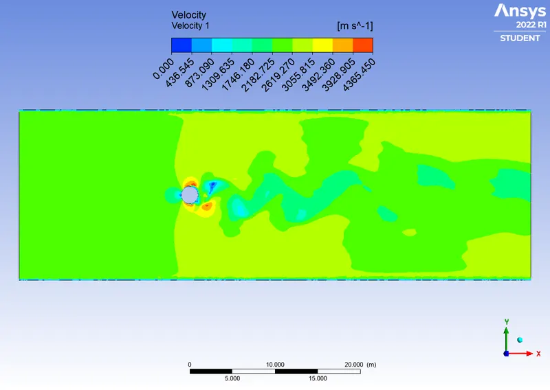
Conclusions:
From the Images and graphs at different Reynolds numbers. One end of the cylinder pressure is less than free stream, according to experimental measurement. It follows that the actual fluid produces a significant pressure-drag force. Additionally, the streamlines do not have y-axis symmetry. A wide, pulsing wake is created as the flow breaks from the ream surface.
The Karman Vortex Streets, which are a stable configuration for vortex pair, are composed of pairs of vortices that alternately shed from the upper and bottom portions of the real surface to form the wake. Only within a certain range of Reynolds numbers (Re)—typically over a limiting Re value—can a vortex street be detected. As Re increases, the wake structure becomes more complicated but the alternating shedding can still be detected at Re=10000000. The shedding frequency is defined by the non-dimensionless Strouhal number. Vortex shedding is a viscous flow that evolves into unsteady motions because of flow instability.
REFERENCES
https://www.mpoweruk.com/flight_theory.htm
https://www.thermal-engineering.org/what-is-boundary-layer-definition/
The complete report (https://youtu.be/x8pXxZRx1RY) is attached to this answer. Ansys animation video: https://youtu.be/x8pXxZRx1RY. As my ansys is crashing every time I save a video, so I recorded for one