Week 2 Challenge : Surface meshing on a Pressure valve
Aim : Surface meshing on a pressure valve
Objective:
- Check for the geometrical errors and perform Topology clean up accordingly.
- Set three different target lengths as three different cases and mesh the model.
- Target length = 1mm, 3mm and 5mm
- Element type = Tria
Procedure :
Importing :
Import the geometry into ANSA by selecting File > Open > ansa file which we used for meshing.
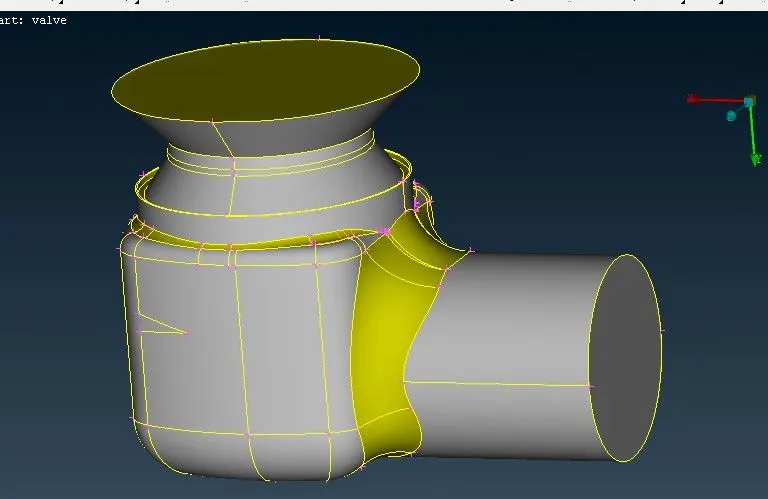
Topological Clean up :
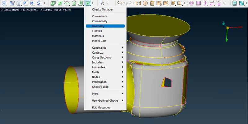
- Perform geometry checks to see the errors presents in our geometry.
- Geometry check can be done by selecting checks and inside it select geometry checks.
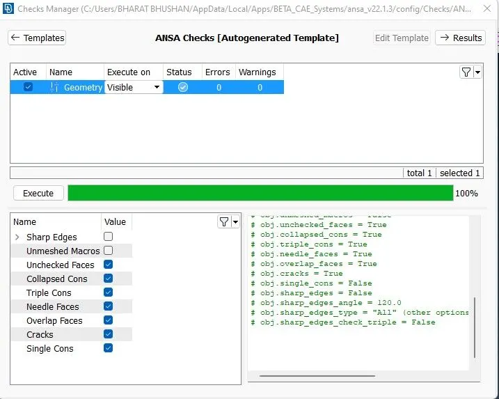
- Inside the geometry checks, select the checks we want to perform, and click on execute.
- After we execute, we can see all the errors presents in the geometry.
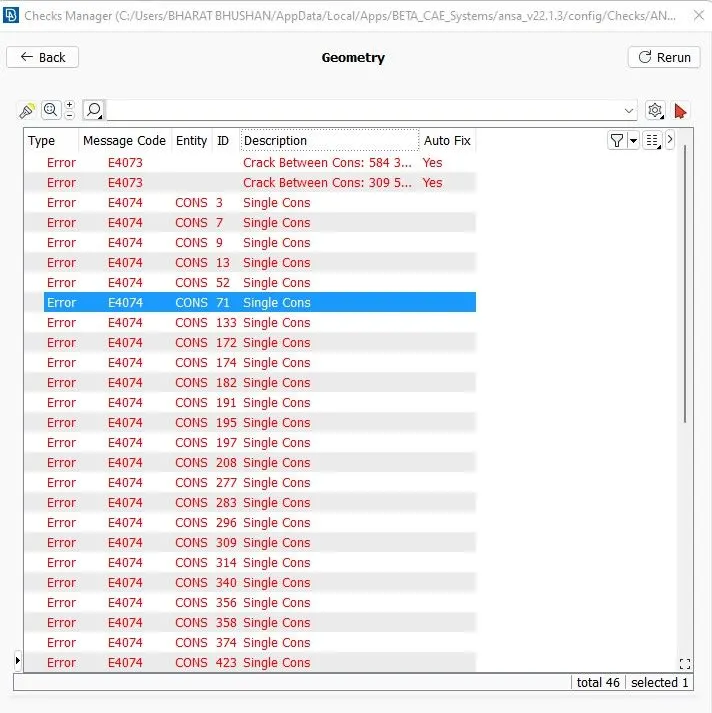
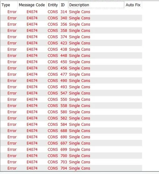
- We can also see the errors highlighted on geometry.
- There are present where there are open surfaces.
- We can click on the error and it will highlight the error in the geometry.
- We can hide the double and triple Cons to see the single cons alone.
- Also we can press ctrl + shift to enter into the wireframe mode and see the error clearly, Single Coons are highlighted in red color.
Methods to fix the errors :
1. Creating a new surfaces :
We can create a new surfaces where there are gaps and open surfaces present in our geometry
This is done by selecting TOPO > Surfaces > New
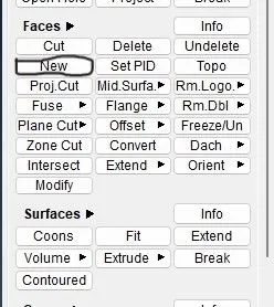
There are four options under new surfaces. There are different types of algorithms present inside the ANSA to create a new surface.
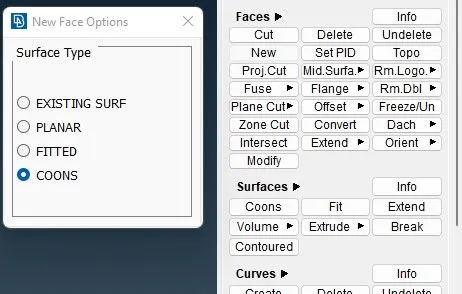
Each option and fix error in our geometry :
1. EXISTING SURF :
This option used to create surface by selecting the Cons.
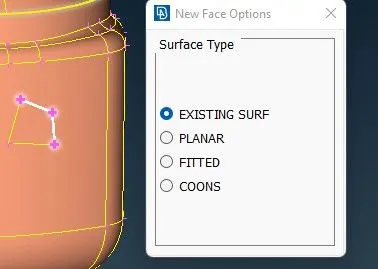
We can individually select cons, or we can use loop option to select the entire loop of cons.
After selecting cons click middle mouse button , and we need to select the face. New Surface is created where there was gas present before
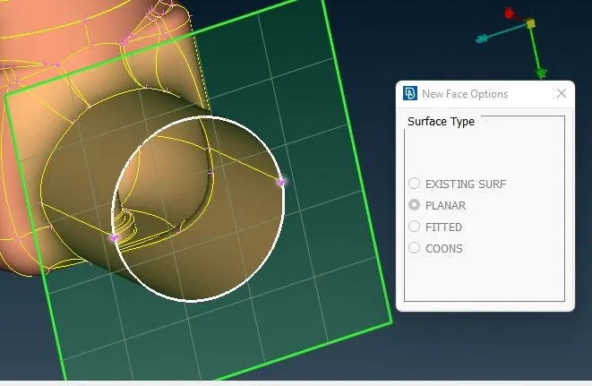
2. PLANAR :
Planer is used to create a flat surfaces, this cannot be used on curved surfaces.
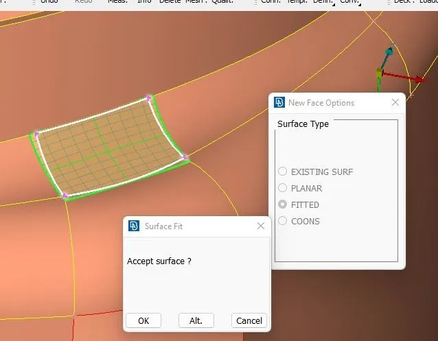
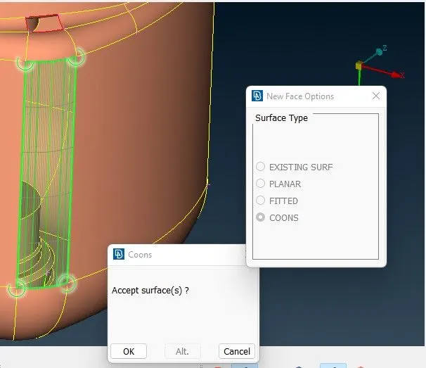
4. COONS :
Surface is created by selecting the coons.
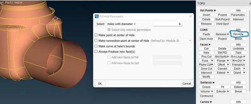
Fill Hole option :
- It is present under cons.
- This can be used to fill large and small holes which are present in the geometry.
- Select the cons and the hole is closed with the new surface.
- We use all the options we discussed above and fix the geometry and check for error again.
- Even through there are no error, check the geometry if there are open surfaces present, since we need closed geometry to create a mesh.
- We have a open surfaces at the bottom surfaces.
- Create new surface by COONS.
- Peform geometry check, we can see there are three CONS error present .
- This is present where we created a new surface to fill the hole in bottom surface.
- This is not actually an error, as we have deliberately created a surface where there was gap to close the geometry.
- It indicates there are three surface are connected, we can ignore this error.
Creating PID's :
After topological clean up next step is to create PIDs.
Enter into PID mode by selecting PID option
Click on the properties options to see the PIDs present, since we haven't created any PIDs the only PID present in the default PID which includes whole geometry.
Create individual PIDs for :
- Inlet
- Outlet
- Spring
- Bottom surface
- Valve head
- column
- body
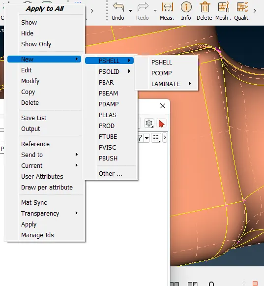
- To create PID's right click, select new, PSHELL, PSHELL
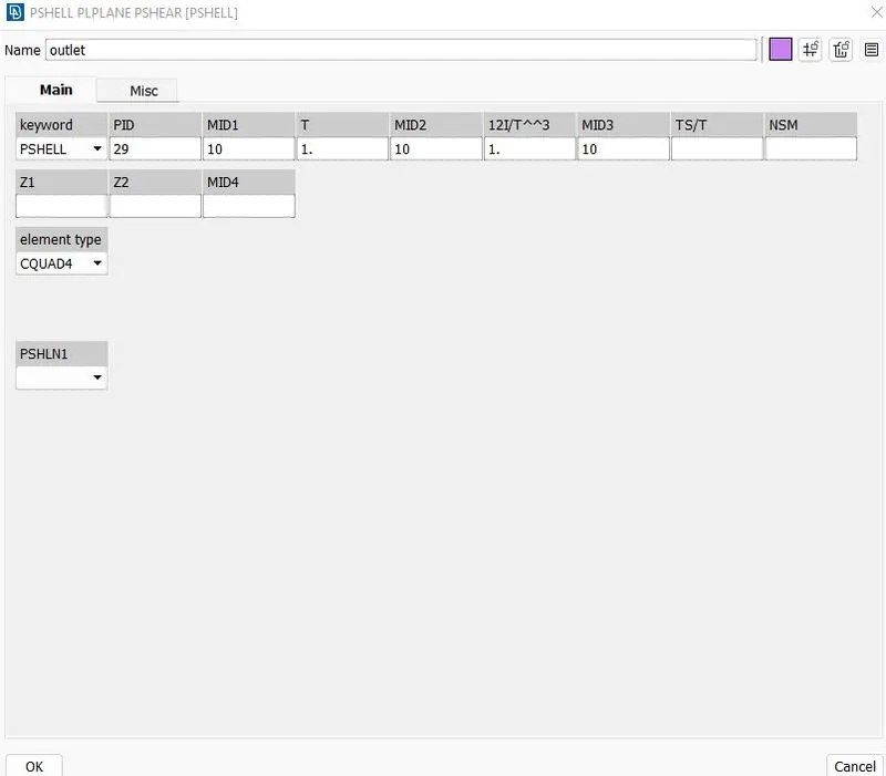
- Create a name for PID.
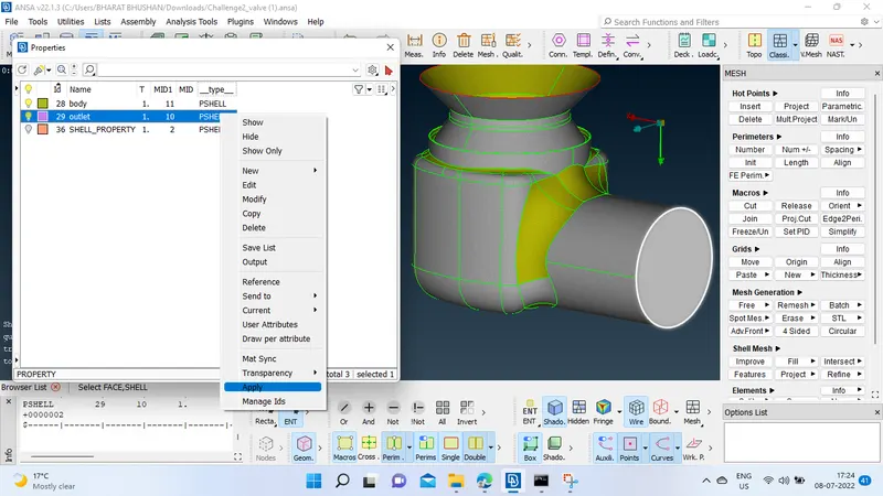
- After right click on the created PID and select apply. Select the surface on which this PID needs to be created and apply.
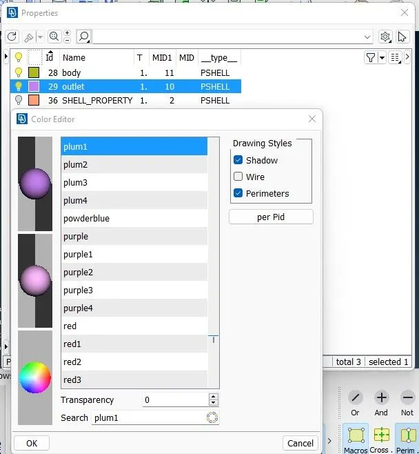
- We can even change the colour of the PIDby doubel clicking on the colour of the PID and select the colour which we can want to apply to our PID.
- Similarly create PID for inlet.
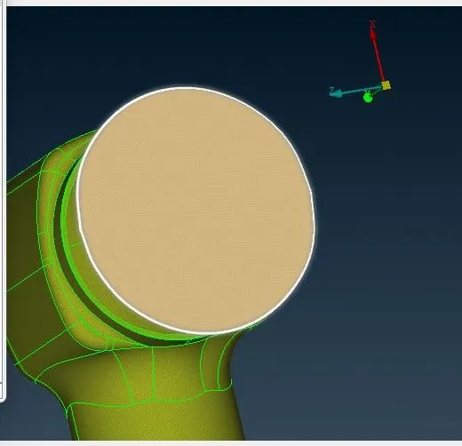
Creating PID for the body :
- Hide the inlet and outlet by turning off light bulb in the PID properties.
- We can now only see the body, but we can also have some components inside.
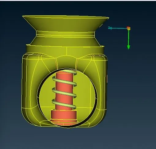
- If we select the body and apply,even the inside object are selected as body.
- To Select only Surface, select PID region option and this will select only the surface.
- Hide the inlet, outlet and body PIDs to see the inside components.
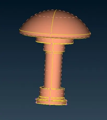
- We have 4 components inside : (1) Valve head (2) Column (3) Spring (4) Bottom Surface.
- First create bottom surface PID.
- Create Spring PID by using PID region option.
Valve Head PID :
- To create valve head PID, first disconnect the attachment between head and column, else the entire object is selected for PID.
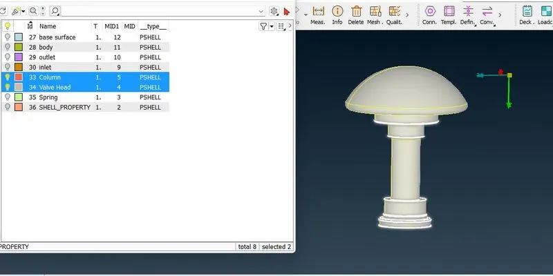
- To fix this hide by attachment by using NOT option which is connecting head and column.
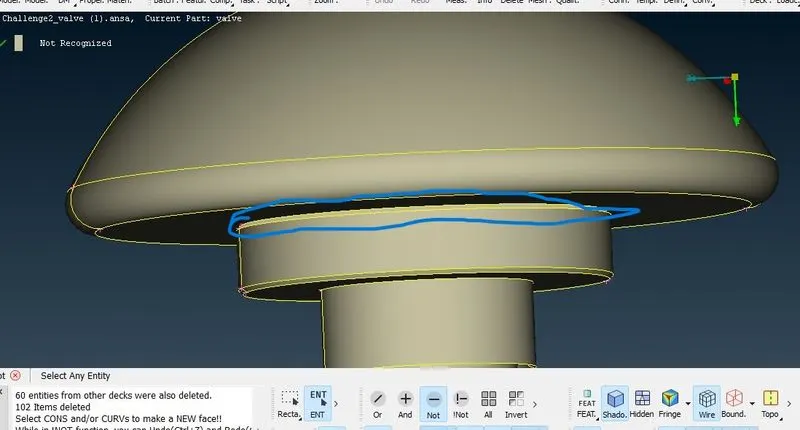
- Now apply the PID for head and column.
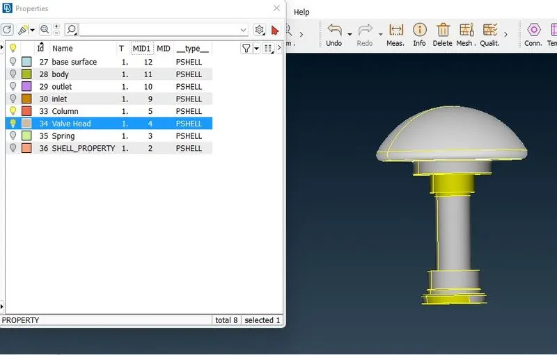
- Now add the connection which we hide to column PID.
- This is done by selecting apply option in column PID and selecting the connection between the column and head.
- Now delete the empty PID which was present by default.
- When we hit delete, there will be error.
- To fix this first select undelete option and then delete the PID.
Meshing :
Individually mesh each PID by hiding the PIDs from the properties
Inlet meshing :
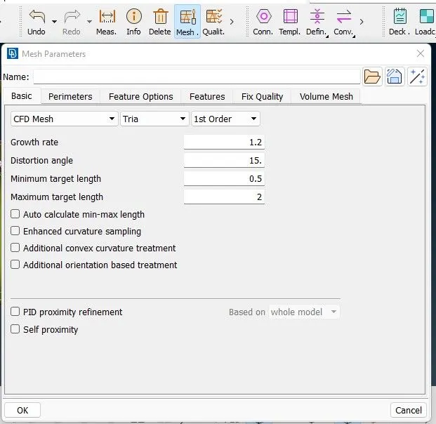
Under meshing select length and give values for Perimeters and Macros.
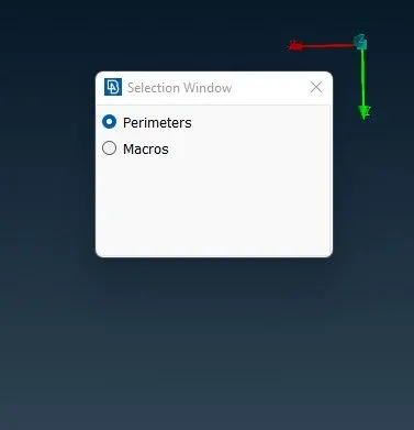
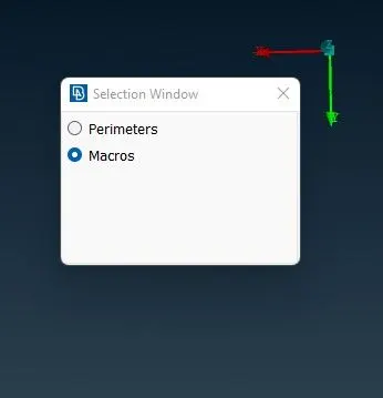
Under mesh parameters give target length as 1mm and element type as Tria and minimum length as 0.5 and maximum length as 2mm
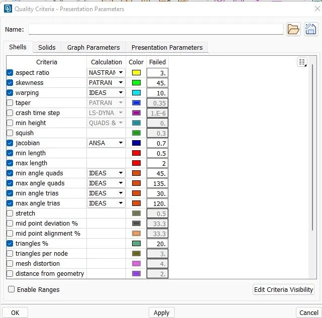
Under Quality criteria give max length as 2 mm and min length as 0.5mm
Now under mesh select spotmesh generate the mesh
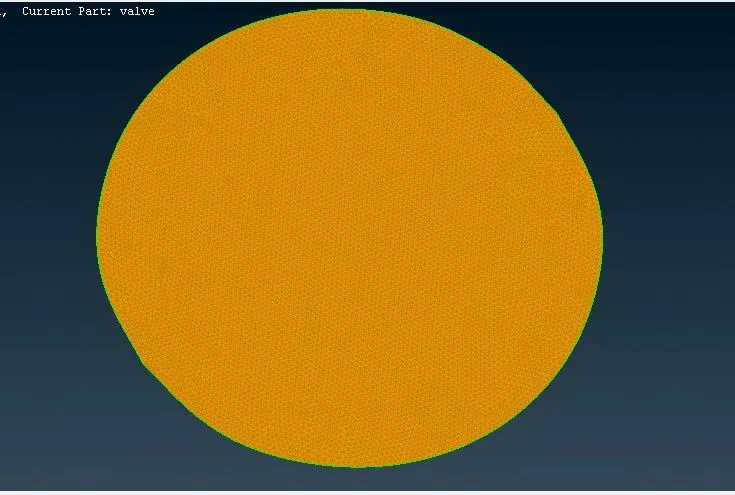
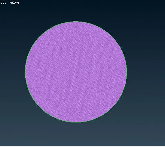
Similarly mesh for each individual PIDs with target length as 1mm
Inlet :
Outlet :
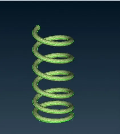
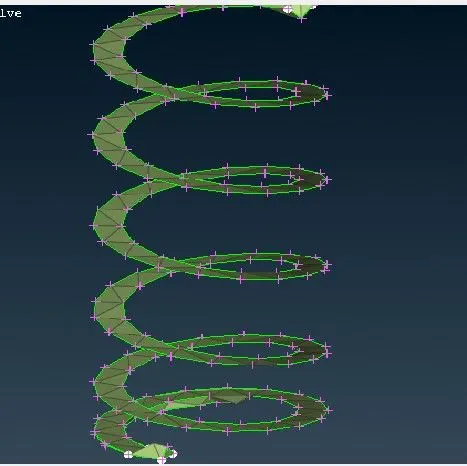
Spring :
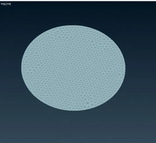
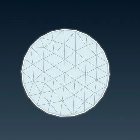
Bottom surface :
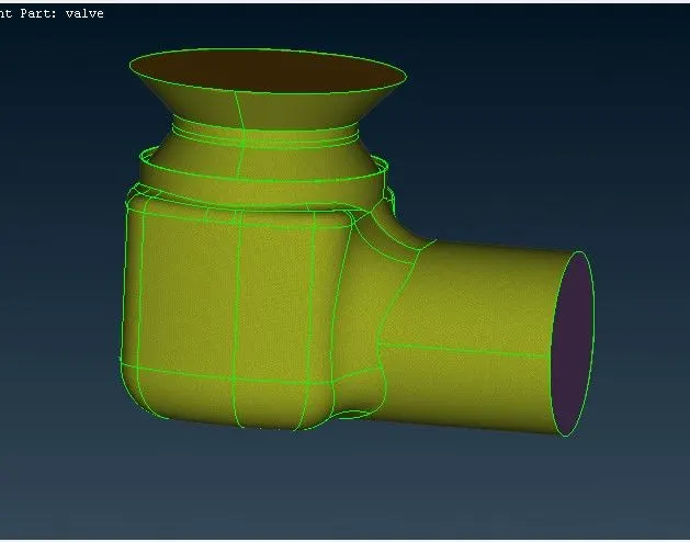
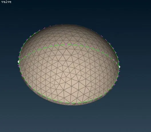
Valve head :
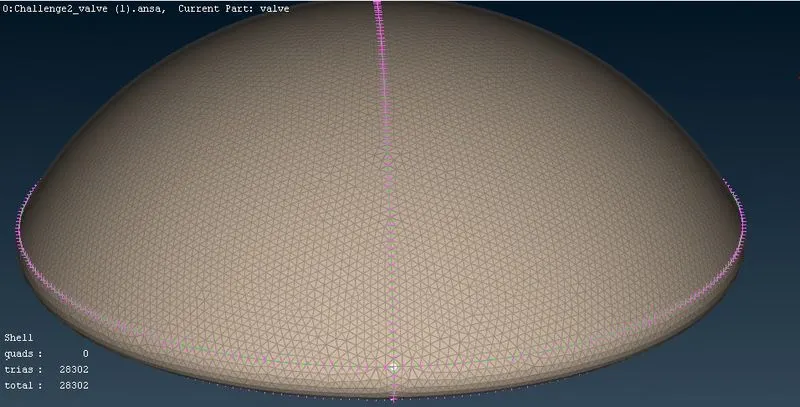
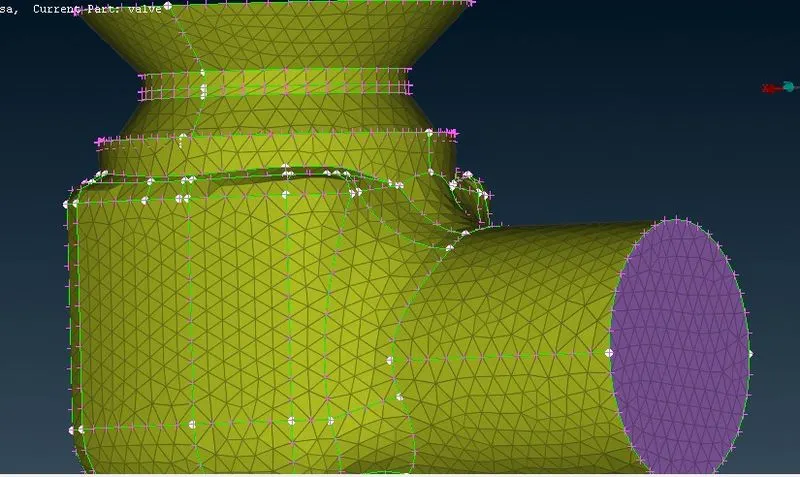
Final Whole body mesh :
Case 2 :
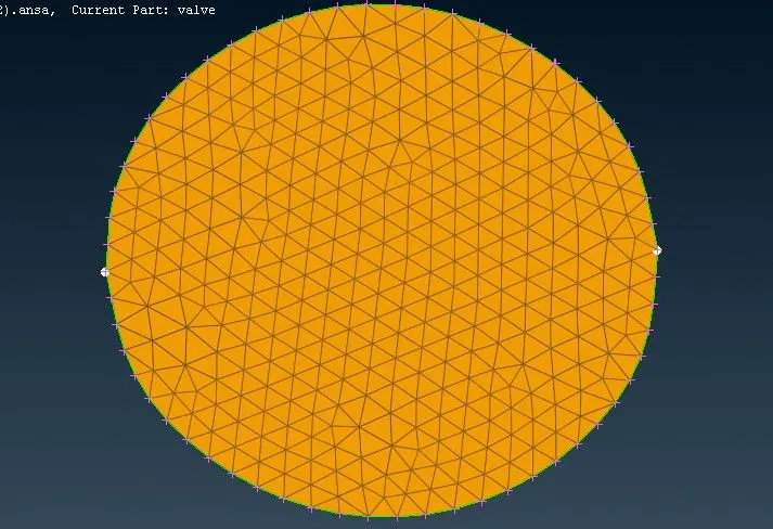
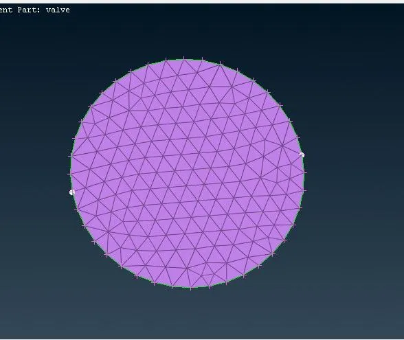
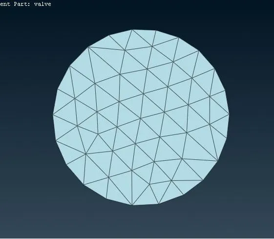
Target length : 3mm
minimum target length = 2mm
maximum target length = 5mm
Inlet :
Outlet :
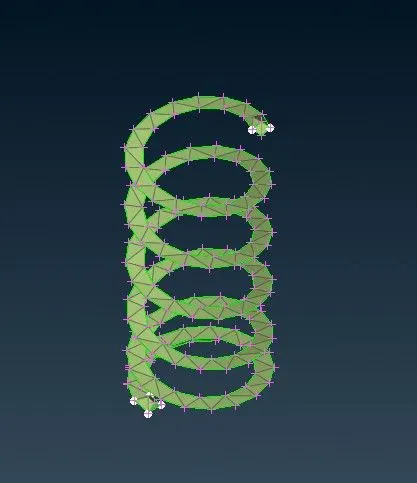
Spring :
Bottom surface :
Valve head :
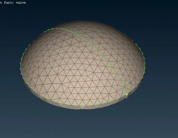
Final Whole body mesh :
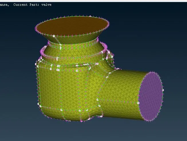
Case 3 :
Target length : 5mm
minimum target length = 3mm
maximum target length = 7mm
Inlet :
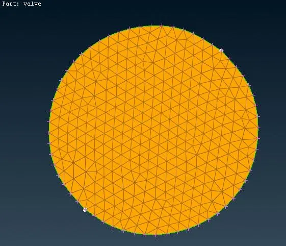
Outlet :
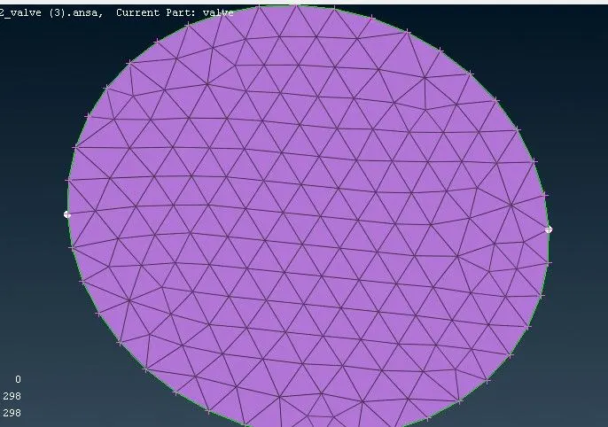
Spring :
Bottom surface :
Valve head :
Final Whole body mesh :
Leaning Outcomes :
Topological correction:
- How to check topological error and fix them.
- Fixing geometric error
- Different types of surface creations
- Filling holes and closing the open geometry for meshing.
PID creations:
- Creating new PID's
- Coloring the PDI's
- Deleting the existing PID's
- Selecting PIDs by PID region and PID option
Meshing :
- Giving values to perimeters and macros
- Setting up mesh parameters
- Setting up maximum and minimum length
- Setting quality criteria
- Generating Mesh
Conclusion :
- The spring mesh in 5mm looks like flat surface because the element size is larger than the smallest distance between two nodes in the Spring.
- 1mm target length captures the curvatures and surfaces very accurately compared to 3mm and 5mm
- Order in which the target element size is better : 1mm> 3mm>5mm