Week 2 Challenge : Surface meshing on a Pressure valve
OBJECTIVE
Perform geometrical cleanup after performing geometry check for multiple checks & rectify them to ensure a close surface for performing a CFD meshing using element size of 1mm, 3mm, 5mm. The nature of element shape should be TRIA element.
GEOMETRY
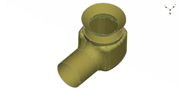
Below is the CAD model required for preprocessing. This model is in raw state where a lot of faces are missing. There also exist multiple single cons which ensures that the geometry is not close. Figure below is in ENT-TOPO mode which shows a clear scope of geometry cleanup.
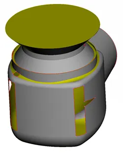
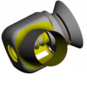
Figure below shows PID mode of CAD geometry. Here evry part has been shown in a single color. We have to assinged PID to every single component so that we can easily handle & speed up our task performance capacity.
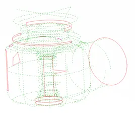
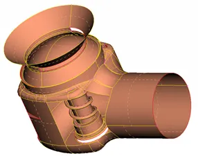
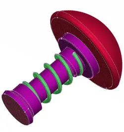
Figure below shows the valve, column & spring before geometry cleanup. We can observe a missing bottom plate & we have to ensure that it must be present before start of meshing because CFD meshing requires a close surface.
GEOMETRY CLEANUP
Below images shows that geometry hs been repaired by inserting missing faces. This also results in removal of all single cons because there is no red color lines which represents single cons. This is a closed surface and after assinging PID it is in a condition to be mesh.
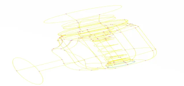
There is a tripple con present as shown in cyan color. This has been verified that there must be 3 surface instead of error. Details regarding PIDS has been dissvcused in next subtopic.
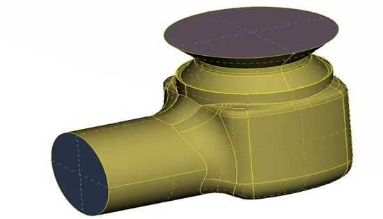
PID ASSINGMENT
After performing geometry cleanup , we must assign different PIDS to different component. It makes eaiser to select every individual component & also switching among them is too easy.
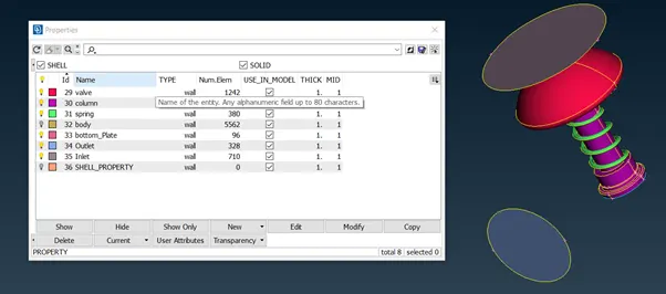
Above images shows the details of assigned PID. Every component can be identified by different color as shown.
MESHING OF PID’S
This is the method pf dividing the CAD model in finite number of small elements. This is known as discretization of our CAD model into FVM or FEM. It ensures that our cad model is divided into finite number of volume or elements of small size. We can also have control of element shape & size.
For this particular project we will use only Tri shaped element. This shape is of 2D in nature. We do have quad shape element for 2D surface meshing. The Tri mesh (Unstructured) are comparatively easier to generate because of the availability of the automated mesh generator.
MESH SIZE – 5mm
- INLET & OUTLET
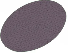
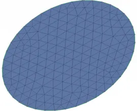
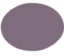
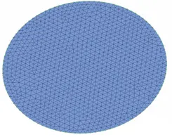
Images in blue color shows outlet & grey color image shows inlet. Meshing size is of 5mm target length & minimum element size is of 3mm & maximum element size is of 5mm. Also the shape of element is tria in nature because its easy to construct\
2. VALVE, COLUMN & SPRING
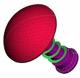
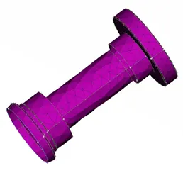
Above images shows the meshing on the surface of valve along with column & spring. Here the column & spring has distorted due to bigger element size. This shows that there is a huge scope of improvement in meshing size to capture the spring accurately.
3. OUTER BODY
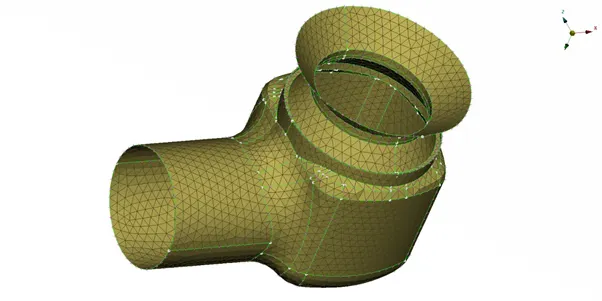
Below image shows that mesh has been captured accurately on outer body using 5mm target element size using TRIA shape element.
MESH SIZE – 3mm
1. INLET & OUTLET
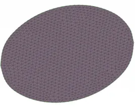
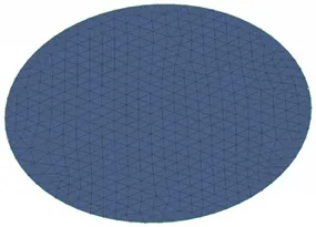
Here element size has been reduced to 3mm target size along with maximum element size as 5mm & minimum size as 1mm. It resulted into increase in number of elements.
2. VALVE, COLUMN & SPRING
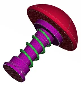
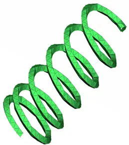
Here we can observe that there is an increase in surface mesh quality of spring. It seems to be less distorted wrt 5mm element size. This will also yield better result wrt 5mm element size.
3. BODY
Below image shows that mesh has been captured accurately on outer body using 3mm target element size using TRIA shape element. Better result can be seen at 3mm size wrt 5mm.
MESH SIZE – 2mm
- INLET & OUTLET
Here element size has been reduced to 2mm target size along with maximum element size as 3mm & minimum size as 1mm. It resulted into increase in number of elements with best surface meshing among all 3 sizes.
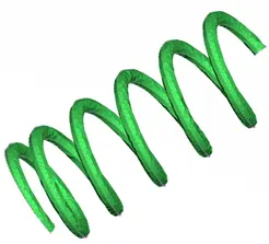
2. VALVE, COLUMN & SPRING
Here we can observe that there is an increase in surface mesh quality of spring. It seems to be least distorted. This will also yield best.
3. BODY
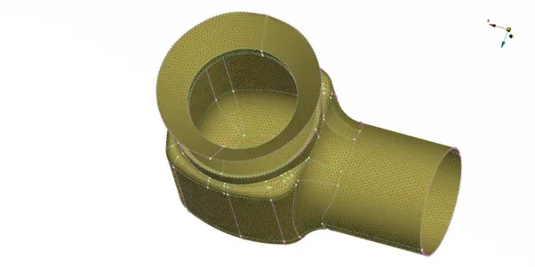
Below image shows that mesh has been captured accurately on outer body using 1mm target element size using TRIA shape element. Best result can be seen among all three size.
CONCLUSION
- SPRING has distorted most in 5mm meshing due to large element size
- Meshing with 2mm element size gives the best possible surface meshing for all other component alongwith spring
- The best possible meshing has been observed with least element size.