Week 2 Challenge : Surface meshing on a Pressure valve
Surface Meshing on Pressure Valve
Aim:
Check for geometrical errors and perform Topology cleanup for the given model and set three different target lengths as three cases and mesh the model.
Target Length = 1mm, 3mm, 5mm
Element Type = Tria
Steps involved:
1. Import the Geometry
2. Do Topology cleanup to fix the geometrical errors
3. Create PIDs for each component of the Pressure Valve.
4. Mesh all the components of the Pressure Valve with given Target Length.
Importing the Geometry
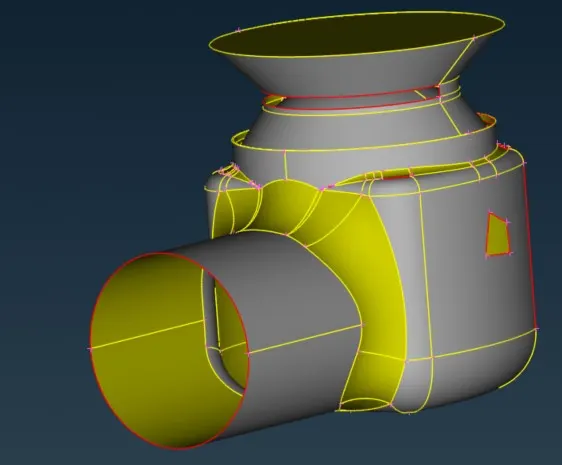
Open Ansa Software and select CFD in the Layout menu given in ANSA window. Go to File à Open and select the model that has been downloaded.
Cleanup to fix the errors
Do a geometrical check to get all the errors present in the geometry.
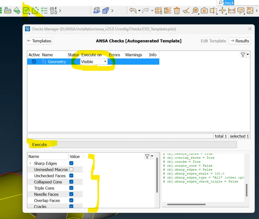
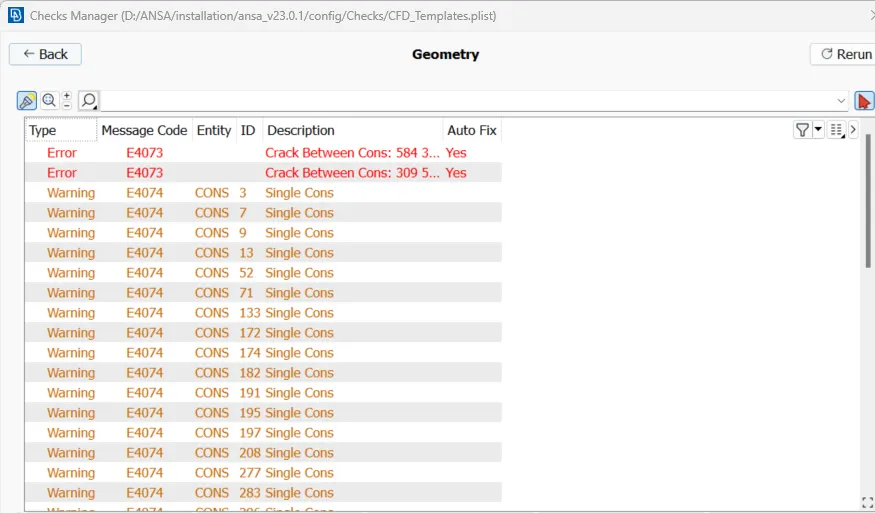
To do the geometrical cleanup we use New Face Options and fill hole option given in the Topo Deck.
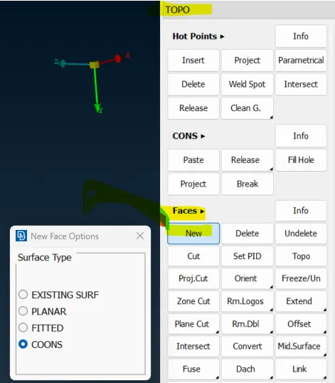
Existing Surface – it is used to fill the surface that is already existing in the model. We need to select the conns middle click and select the surface where the gap is present.
Planar – It fills the gap in the Planar surface.
Fitted and Coons – It fills the gap in such a way that is fitted to match the surface.
Fill hole – It fills the hole Present in the model
By using the above cleanup options we have fixed all the errors.
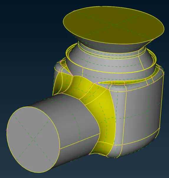
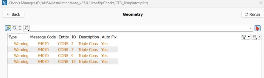
Create PID for each component of Pressure Valve
PID is created to give different mesh Length Value for each component to get the accuracy of the result.
Create new PID by clicking on the PIDs icon and then right clicking inside the Properties windows and click New à Shell_Property.
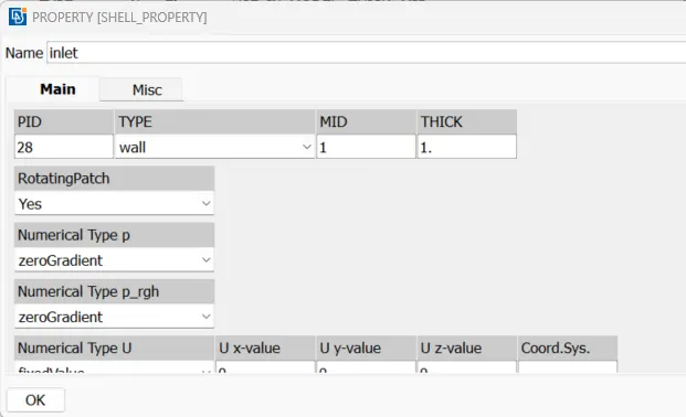
Create the below given PIDs for each component.
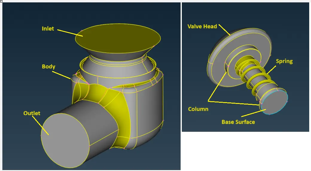
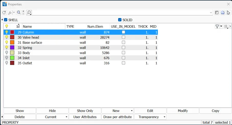
Selecting the component
We can select components by Entity, PID-wise, or PID region-wise
Entity Method – It requires selecting each surface to select the particular component.
Entity Method – Once we have created the PID, We can select that particular PID to select the component.
PID Region Method – It will select the surfaces PID region-wise. It means the selection will keep on go, until we have some break between the two components.
Meshing the Component
1) Enable Mesh Deck à Perimeters à Length à Select Perimeters à Select the Model à Middle click
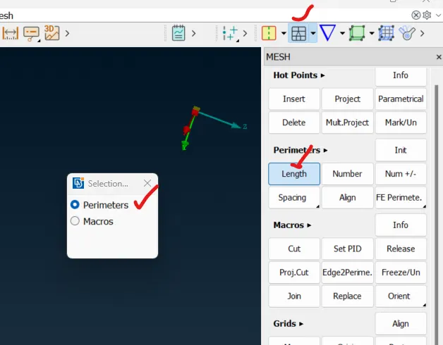
2) Give Length 1mm in the following pop-up window
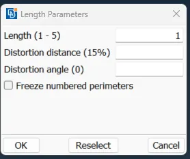
3) Then click on the Macros and follow the same to give a Length 1mm
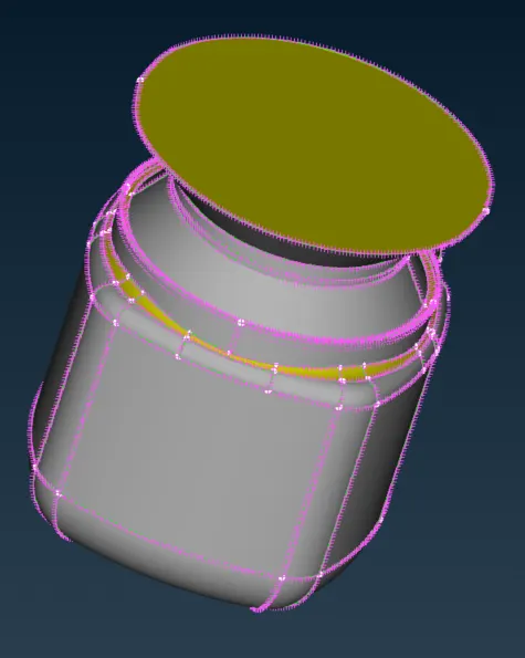
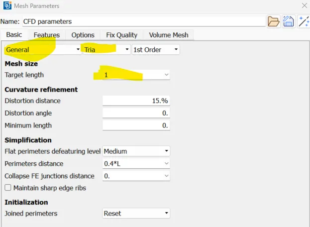
4) Give target Length in Mesh Parameters
Mesh Parameters à General à Tria à Target Length 1mm
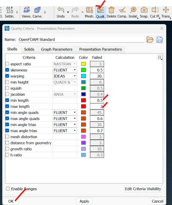
5) Quality Criteria à min Length (0.5) à Max Length (2) à ok
6) Mesh Generation à Spot Mesh à Select the Model à Middle click, Mesh will be generated.
Output
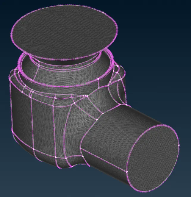
Target Length – 1mm, Element Type – Tria
Outer Body
Inner Components
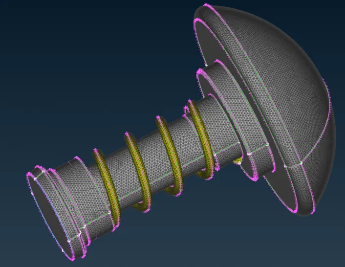
Inner components meshed smoothly with a mesh length of 5mm
Target Length – 3mm, Element Type – Tria
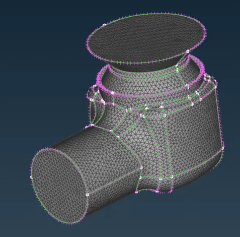
Outer Body
Inner components
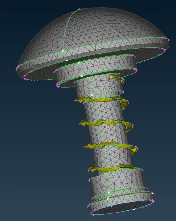
Inner components are not meshed properly with a mesh length of 3mm
Target Length – 5mm, Element Type – Tria
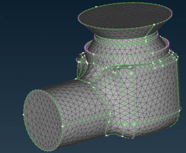
Outer Body
Inner Components
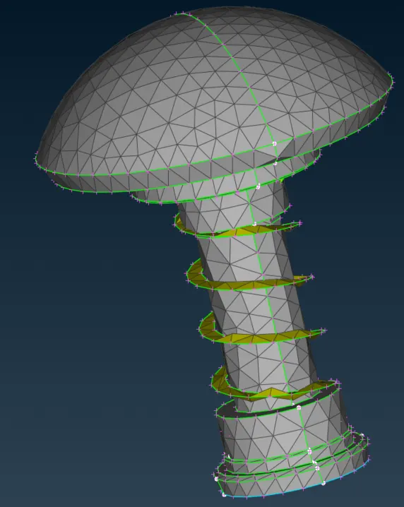
Inner components are not meshed properly with a mesh length of 5mm.
Conclusion
Opting for a finer mesh size in numerical simulations enhances accuracy by capturing intricate details and variations in geometry and stress distribution. However, this heightened precision comes at the expense of increased computational time, as the solver must contend with a larger number of elements, intensifying complexity and extending simulation durations.
To address this trade-off, a strategic approach involves tailoring the mesh size based on the characteristics of different parts within the model and the required level of accuracy. Specifically, for the outer casing, where extreme precision may not be critical, a coarser mesh with a target length of 3mm can be employed. This mitigates the computational burden associated with fine meshes while still providing satisfactory results for less intricate regions.
Conversely, for smaller and more intricate components like the spring and column head, adopting a finer mesh with a target length of 1mm becomes essential. This localized mesh refinement in critical areas ensures a heightened level of accuracy where intricate structural behavior or stress concentrations demand a more detailed representation.
In summary, by strategically adjusting the target mesh length according to the specific characteristics and criticality of different components, this approach optimizes the balance between computational efficiency and accuracy in finite element simulations.