Week 2 Challenge : Surface meshing on a Pressure valve
Aim: Surface meshing of pressure valve with different target length.
- Target length = 1mm, 3 mm and 5 mm (i.e. 3 cases)
- Element type = Tria
Procedure
- Topo-Cleanup:
- The first thing need to be done is to check for single cons and triple cons in the model. Sinle cons are cons that are shared with one surface only which indicates open surface. Such open surfaces are not expected in a closed geometry so that need to be resolved. Triple cons are formed due to con shared with three surfaces and that also need to be resolved on the basis of weather it is desired on that place or not. Triple cons are not always errors but that shows the local volume may form due to those faces. These single and triple cons are identified using Geometric checks.
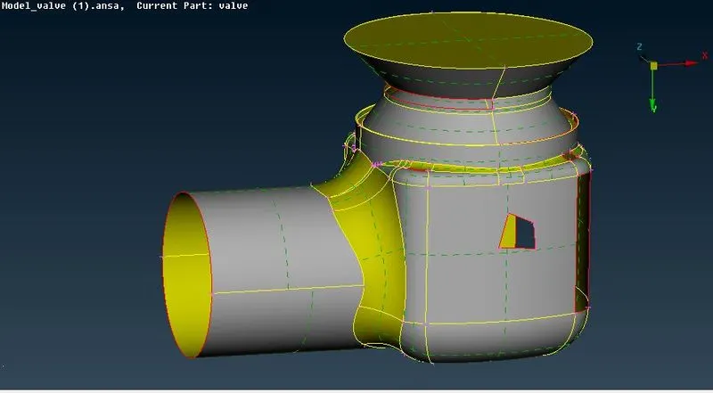
Figure 1
- It can also be seen by disabling the double cons from bottom bar with wire frmae mode (cntrl+shift). We observed various single cons and few triple cons. There are few open surfaces that are forming single cons and it is filled by creating surfaces in FACES option.
Faces - New - COONS / Fitted / Existing Surface/ Planar - suitable option is selected accordingly and surfaces are filled.
- At many places the one or more than one of these options may give satisfactory results, so suitable method is chosen based on most satisfactory surface creation. For a closed regions we also can use Fill hole option, under CONS section inside ‘Topo’ Deck.
- In a complicated geometry forming a whole surface may not work properly so surface need to be created in small parts. Geometry should be closed for CFD analysis so surface at bottom , top and at side are closed using fill hole option or Coons option.
- At the bottom hole the triple con is formed after closing the surface and that triple con is obvious there due to three surfaces are coming in contact, so it is not treated as an error there.
The final model after topo-cleanup will be free from single con, undesired triple con and unnecessary surfaces as shown in figure.
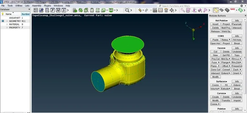
Figure 2
2. PID Allocation - PID is property ID , used to store the specific information about geometrical entities , apply boundary conditions for CFD application. Whole geometry is divided into number of PID’s. PID’s are created by using :
Open PID Window – Right click – New - name the PID – as Body , Inlet, Outlet, Head, Spring, Column, Base plate.
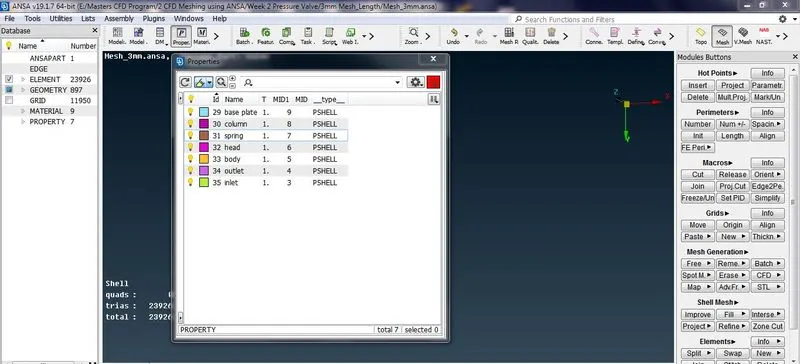
Figure 3
- All created PID’s are allocated using PID allocation : Right click on PID name –Apply –Select the part that we need to assign that name –Selection of the part can be done using ENT mode (will select entity wise), PID mode ( will select PID wise) or PID region ( will select region wise taking any discontinuity in connection as one entity) –ok
3. Meshing
- Any small surfaces or cons or region between two nodes having length less than desired mesh length need to be removed having no significance which may result in mesh failure at that location by using cut.
Faces –cut –Right click on the con –It will show history of the removed con in orange colour
- Meshing can be done directly for whole geometry here if all the components have same mesh length or The components having different mesh length can be meshed PID wise using Spot Mesh option. Before Mesh Generation we need to provide Length as Perimeter and Macros with Mesh Parameter and Mesh Quality Criteria.
Mesh is generated for three lengths 5mm, 3mm,1 mm respectively.
Figure 4, shows the pressure valve for 5mm.
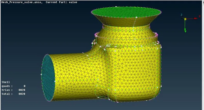
Figure 4
Figure 5, shows the inner part of pressure valve.
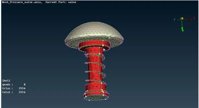
Figure 5
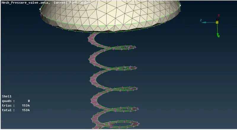
Figure 6
From figure 6, the mesh length of 5mm distorts the original profiles of head and spring
Figure 7 & 8, shows the pressure valve for 3mm.
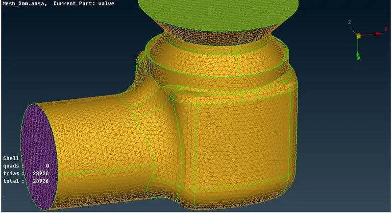
Figure 7
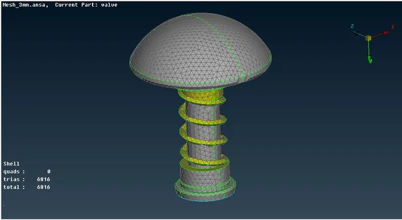
Figure 8
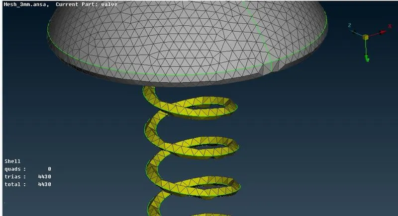
Figure 9
Mehsh length of 3mm also fails to capture the spring profile free from distortion.
Figure 10 & 11, shows the pressure valve for 1mm.
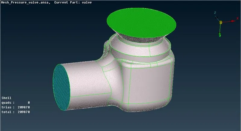
Figure 10
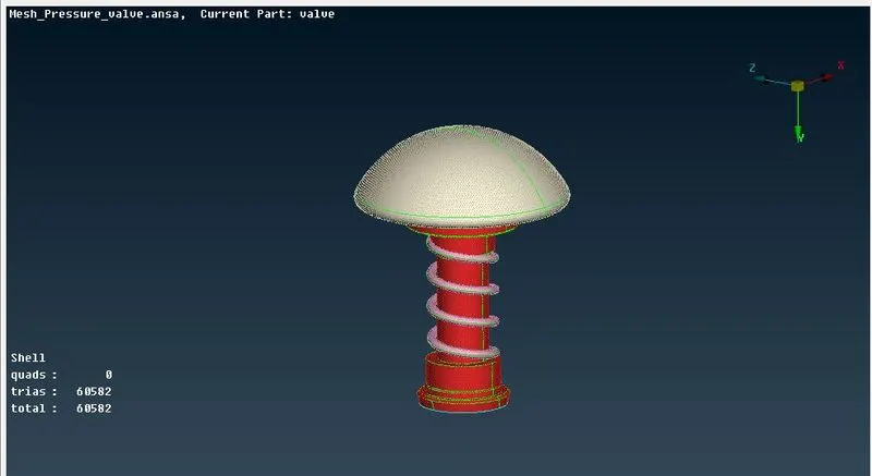
Figure 11
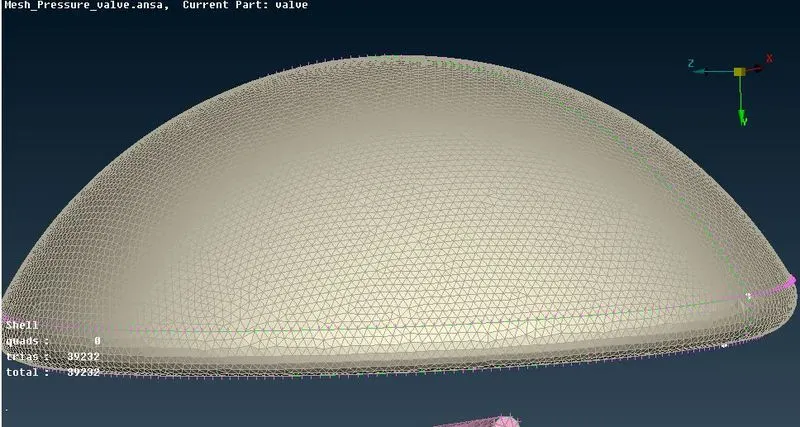
Figure 12
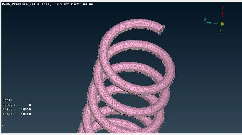
Figure 13
- The mesh length of 1mm captures the spring and head profile without any distortion in shape.
Conclusions
1. Mesh size of 1mm will be more suitable as compared to 5mm and 3mm due to accuracy in capturing exact profiles of spring and head which are free from any distortion of surfaces. This also verify that when ver the mesh length exceeds the size of any geometrical entity it tends to distort the geometry which may led to wrong interpretation of physics happening at that location and may also cause error in transforming information from neighbouring cells.
2. As mesh size becmes finer the number of cells increases rapidly. So the differnt mesh zise for different component will we suitable to avoid usage of more computational resources and computational cost.