Week 2 Challenge : Surface meshing on a Pressure valve
AIM : To do the surface meshing of a Pressure Valve by using tool in ANSA by giving three different Target length which are 1mm , 3mm and 5mm and generate three meshed models.
PROCEDURE:
- Open the given CAD geometry of Pressure valve into the ANSA GUI.
- To starting with, geometry check of the model is needed to get to know about the errors like Single cons, Cracks and unrequired Triple cons present in our CAD model. For that select the Geometry check option and execute the geometry checks which lead to the window where all errors can be seen. (Shown in the diagram below)
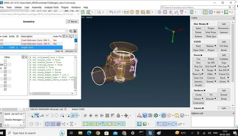
- After geometry check it observed that geometry have some single cons and geometry cracks which are need to be attended. By the help of TOPO cleanup tools those errors can be resolved.
- To fill the surface or to patch the surface, new surface must be created. For that go to the FACES section and select NEW tool. Four types of selection are present in this tool which can use as per their requirement. Another tool is became very useful to patching those surfaces which situated in CONS section named as FILL HOLE , with the help of this tool we can select the hole in one click and then easily create a new surface.
- After patching up the entire surface and removing all the single cons, an error free Geometry remained. (Shown in the diagram below)
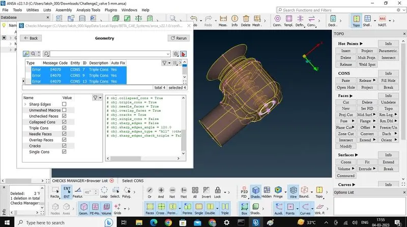
- Now need to Delete those line which are creating very small region because if the region smaller than the given Mesh target length then it cause errors. For that from FACES section select CUT tool and right click on those line which are need to be removed without distorting geometry of the model.
- This model is assembly of different parts, so need to assign PID to each part which made every part accessible and create a differentiation in the geometry.
- After TOPO cleanup done, need to start meshing the surface. Start with 1mm meshing Target length, for that first assign the MESH PARAMETERS as 1mm and select ELEMENT TYPE as TRIA then go to QUALITY CRITERIA and assign MAX length and MIN length of the mesh and at last go to PERIMETERS section and select LENGTH tool and define Perimeter and Macros length as 1mm by selecting the any length or in this case the whole MODEL.
- AT last select the SPOT mesh tool from MESH generation section and select the particular face or in this case the whole model and after middle click a meshed surface generated on each part of PRESSURE VALVE. (Shown in the diagram below)
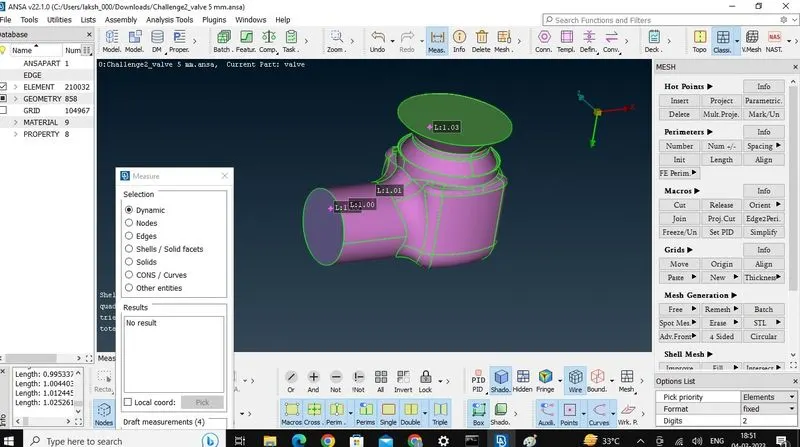
- Repeat the Meshing process by assign mesh target length as 3mm and 5mm.
LEARNING OUTCOME:
This was a basic exercise to get introduce with creating new surface to patch the cracks or to remove single cons from the geometry and also introduce us with the property manager in which we can assign PID to each part in the assembly and can do study and TOPO cleanup individually if needed.
CONCLUSION:
In this particular challenge we need to assign three different target mesh length and generate three different models with that and those Mesh length are 1mm, 3mm and 5mm.
As we already know that the geometry totally obeyed our given Mesh target length and also we know that the smaller the mesh length generate smoother or finer surface of geometry.
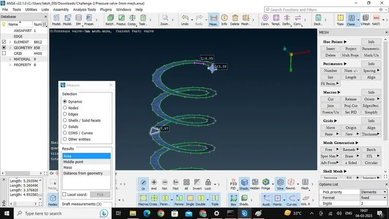
So, in case of 1mm length we get very smooth surface and finer geometry. If we check the geometry of spring we can easily conclude that above statement about mesh length is very much true.
(Shown in the diagram below) 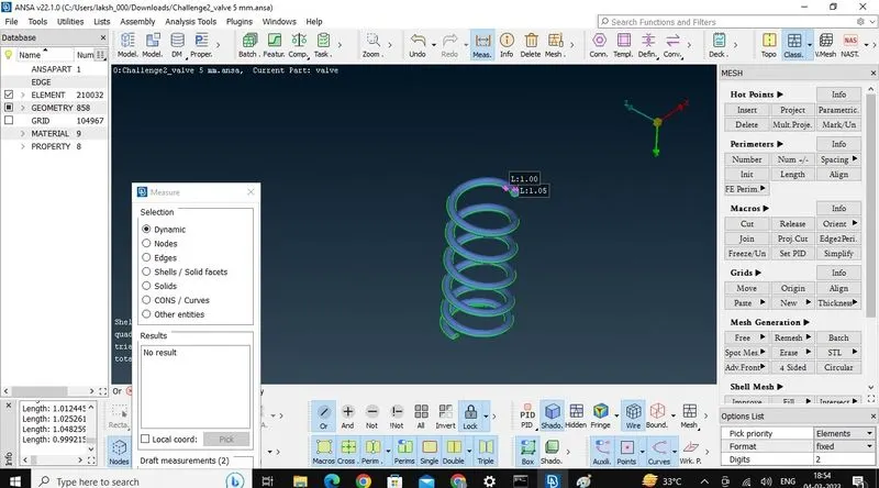
In case of 3mm length, the outer body, valve head, inlet and outlet PID still looks very smooth and fine but Spring PID looks distorted because the given target mesh length is greater than the gap between two closes nodes in the spring.
(Shown in the diagram below) 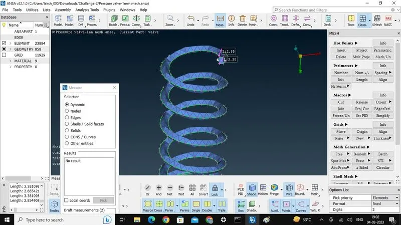
In case of 5mm mesh length, the outer body, valve head PID surface not looks very smoother and finer as before and Spring PID looks totally distorted because the given target mesh length is greater than the gap between two closes nodes in the spring.
(Shown in the diagram below)