Week 2 Challenge : Surface meshing on a Pressure valve
Surface Meshing On a Pressure Valve
Aim :- To write a detailed report on the surface meshing on a Pressure valve and to find out the target length which gives more accurate results.
Objective :- Our objective is to check the geometrical errors and perform topology cleanup for the given pressure valve model and to set 3 different target lengths(1mm,3mm and 5mm) and meshing the model.
ANSA is a pre-processor tool used for Geometry checks,Topo cleanup and for finer meshing.
Topology :- Study of geometrical properties and continuous change of shape or size of figures.
PID - Property identities , Ent - Entities.
Procedure :-
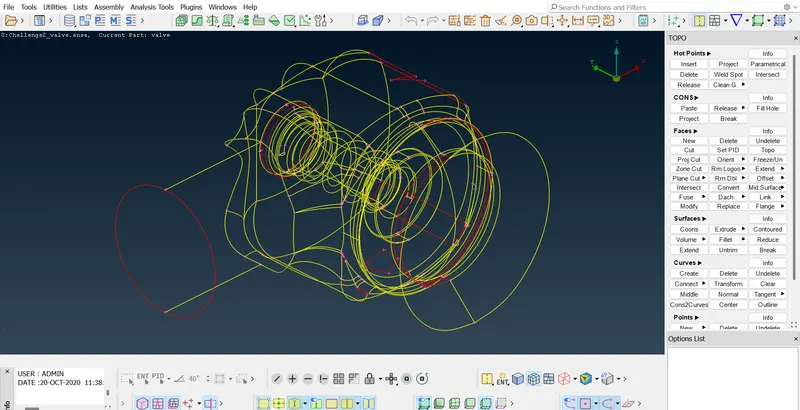
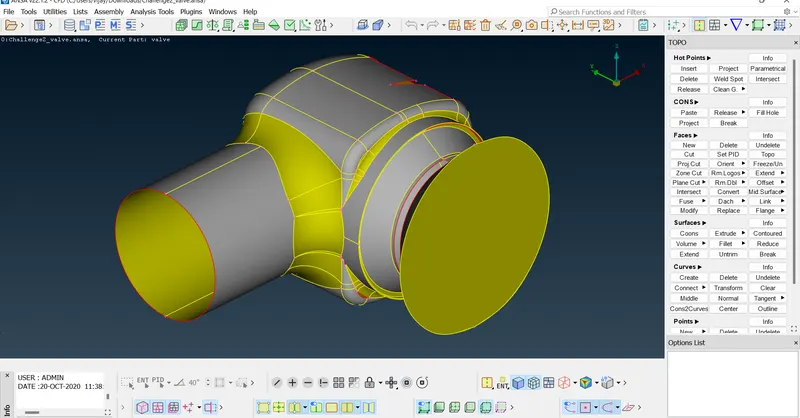
1.Open the '.ansa' file of Pressure valve in ANSA by dragging the file from your Filemanager or by searching the file location and we open it.We can see the model in 'wireframe' mode by default.Turn on 'Shadow' where we can see the 3d model.
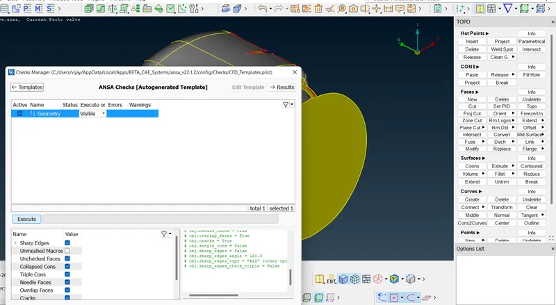
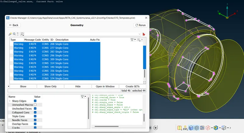
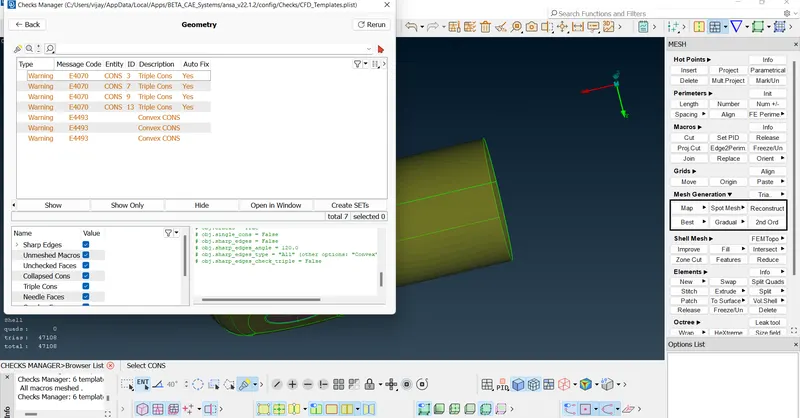
2.Now we have to check the geometrical errors. Go to Checks - Geometry - ANSA checks(Autogenerated template),click on Execute and it will show the errors.
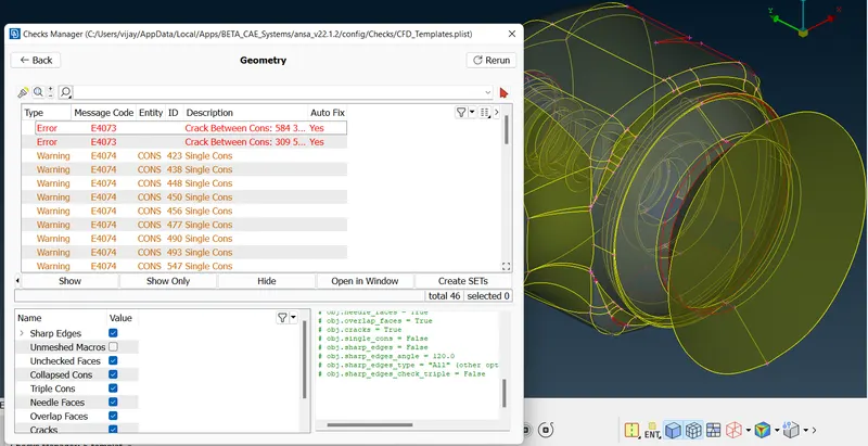
Here we can select all those errors regarding single Cons at a time and see where they are.Also we can see the cracks location
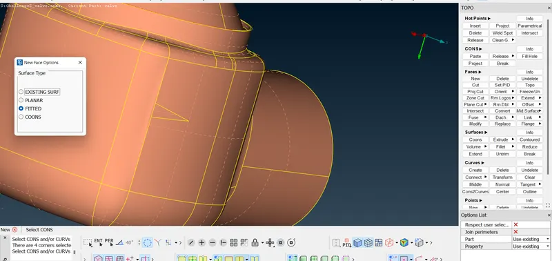
3.Fill the single Cons with Face tool in TOPO. Go to Faces - New - Existing surf/Planar/Fitted/Cons . Also we can use 'Fill hole' option in CONS.Choose the best method which fills the gaps/spaces perfectly.
For 'existing surf' method ,select the Cons and then middle click and then select the face to which it should allign.
For 'COONS' method, select 1CON and then entire surface cons to be filled will be automatically selected as the 'Loop' option is enabled.Fitted is same as the COONS method.
'Planar' method is same as 'existing surf' method but this is mostly use in plain surfaces (not suitable for curved surfaces).
'Fill hole' is mostly used for small type of cracks,holes etc.Also it can be used for some plane surfaces and faces.
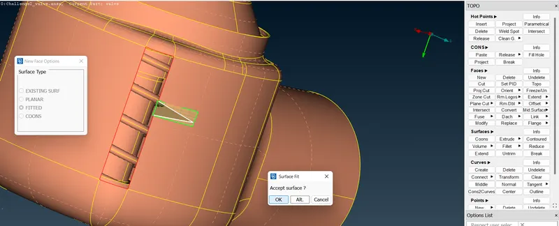
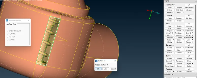
Here the Solid is in PID mode.
Using Fill-hole
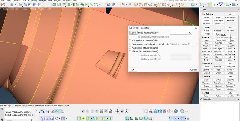
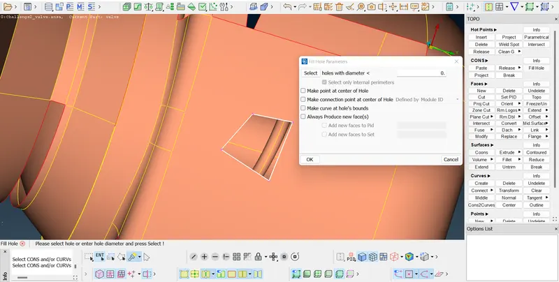
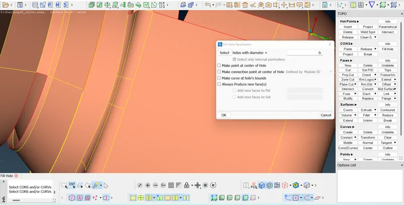
Similarly we can fix all the remaining single Cons.
4.Now closing the single Cons inside the base surface.We can see the Cons perfectly in wireframe mode.Select Cons method and select one half of the surface to be closed/filled first and then the other half.Choose the best surface by clicking on alternate surface.(Click on 'Accept surf' by choosing the best surface).And then we can see there are no single Cons by checking wireframe mode.
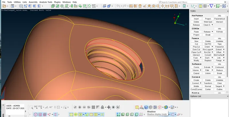
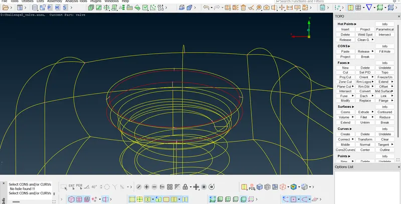
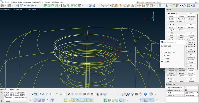
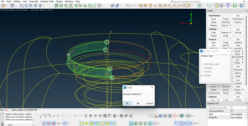
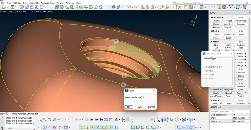
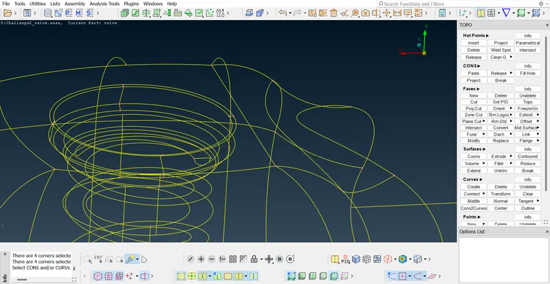
5.After filling all the single Cons, click on Checks - Geometry - Execute , we can see there are no errors and only warnings of Triple Cons etc. which we can ignore.
6.We have to close the openings since we have to do surface mesh.(Inlet,outlet,Base surface)
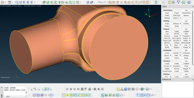
7. OR(/) - It will keep only the selected entities visible.It will isolate that part from the entire model and we click on Invert option then we can see the entire model except the previously selected one(i.e the invert option will make the visibility status inverted). To make visible all the entities of the model just click on All option.
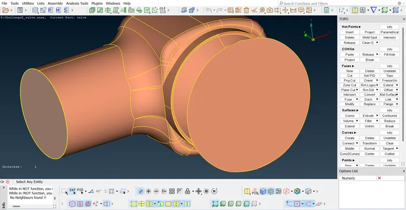
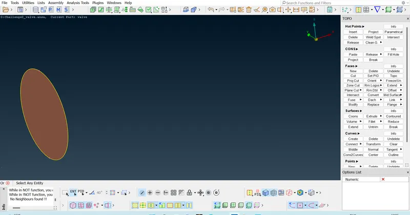
8. Not(-) - It will make the selected entities not visible, And(+) - It will bring back selected entities connected to the selected ones.
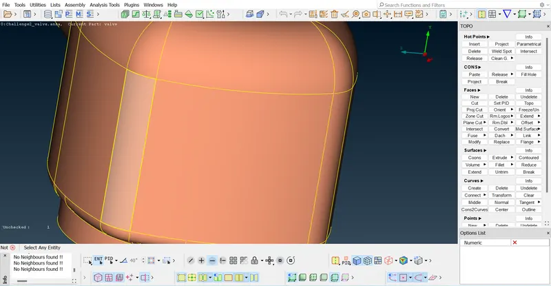
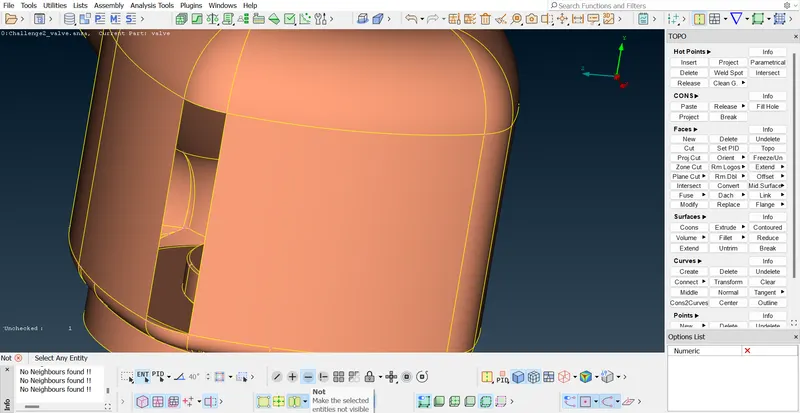
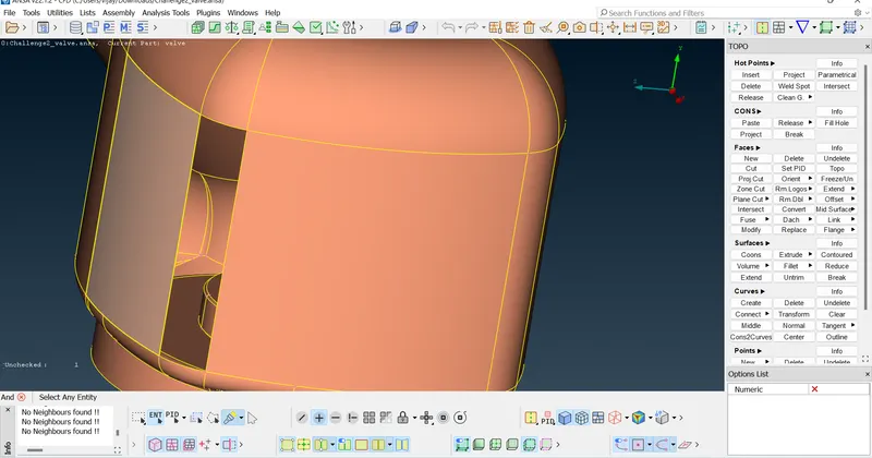
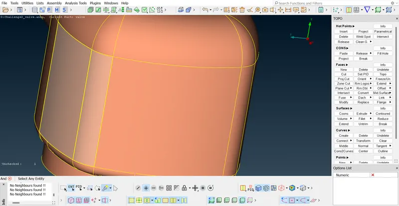
9. !Not - It works as Not + Invert. When we select '!Not', first we can hide a selected face and then if we do middle click the visibility status is inverted.(i.e, we get the hidden part and the entire model will be disappeared).
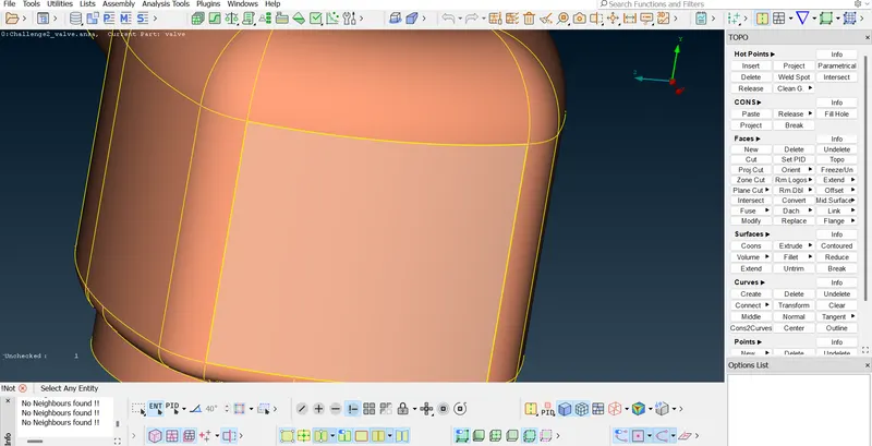
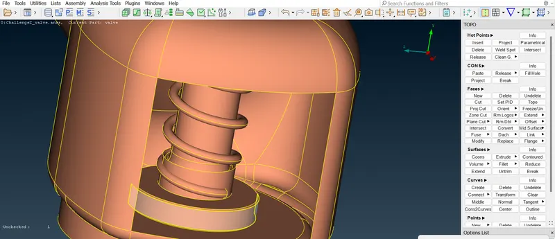
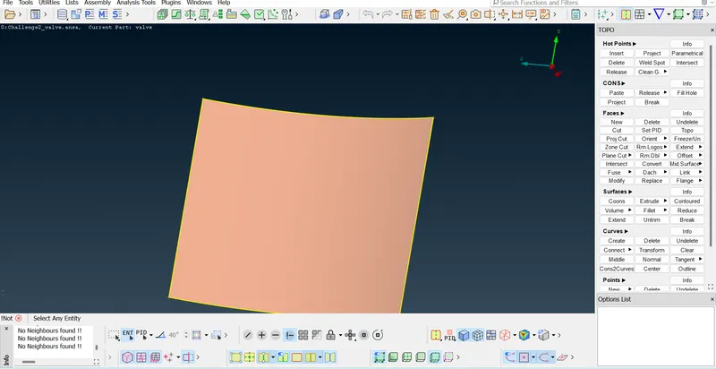
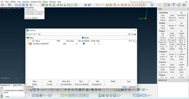
10.Assigning PIDs,modifying names - click on Properties and shell_property PID is available by default.
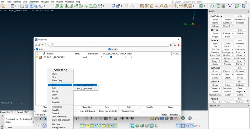
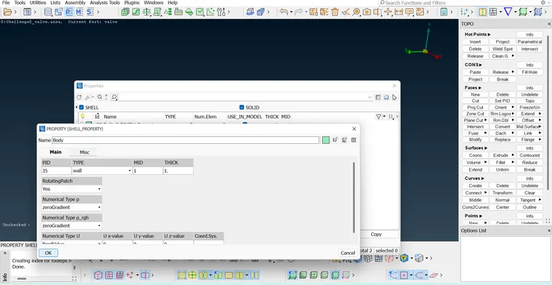
Now inorder to create new PID we have to do right click on Properties panel and go to New - SHELL_PROPERTY and give the names for different parts.
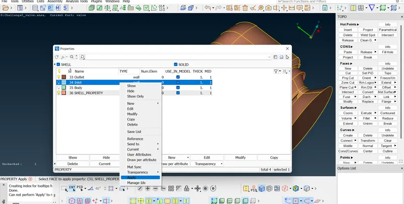
To assign a particular PID to particular face or particular part we have to right click on Properties panel and then go to apply and select our required entity.
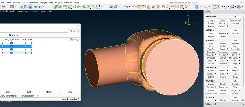
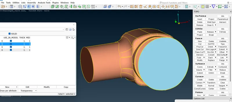
Similarly to assign 'Body' select PID region option and then click on surface of the model and select it and then do middle click.
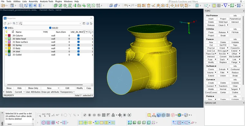
Click on 'Not' and hide outer surfaces and then assign Valve head,column,Spring.(inner parts).Before going for meshing we have to delete the dummy PIDs.As we click on Shell_Property to delete it shows a deleted faces are there , so we shall use 'Undelete' option and then click on cross hatch of the outlet face and then do middle click,we can see mixed colour in outlet.Now we can delete the shell_property and no error will be shown.
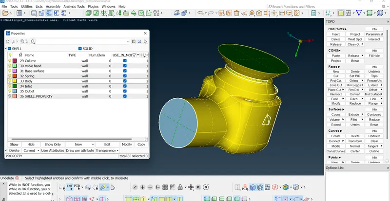
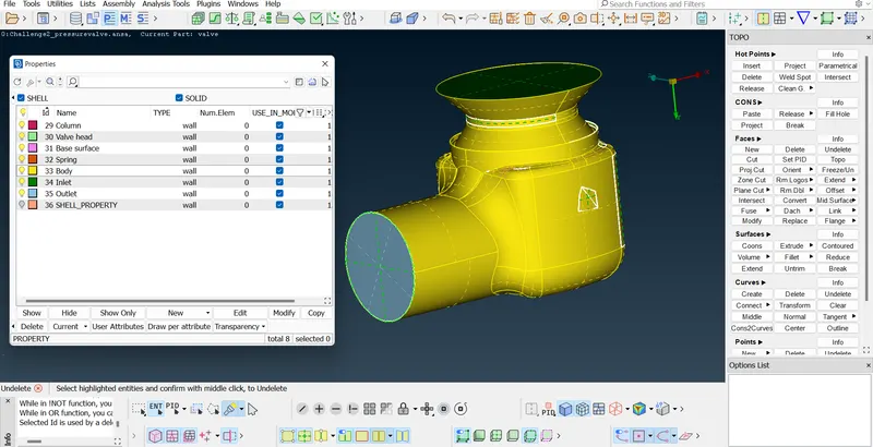
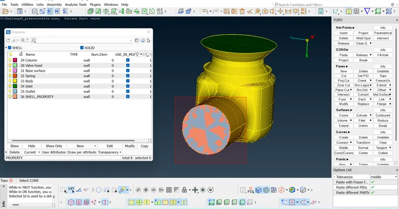
Also we can change the colour of entity whenever we want
11.Before starting meshing we have to give Target length as required - 1mm or 3mm or 5mm and then go to quality criteria and give the minimum and maximum length respectively.
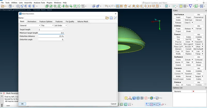
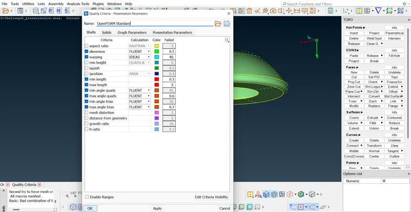
11. Now go to meshing,click on length - Perimeters - Boxselect - select the entire outer surface and give the target length as 1mm or 3mm or 5mm and repeat the same process for macros. And then click on the inlet and outlet and do middle click,mesh is generated
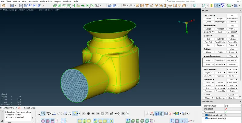
And for inner parts(valve head,column head,spring) isolate them by hiding outer surfaces by using Not option and lock the view inner.And now do the meshing process same as per the outer surface.
Results :- (After meshing the outer and inner parts)
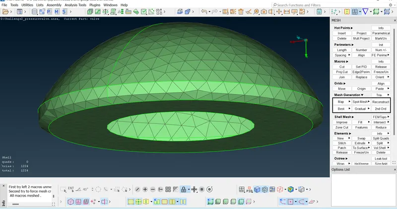
Valve Head meshing :-
Target length = 5mm,3mm&1mm
Inner parts:-
5mm
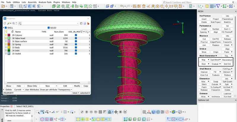
Valve head
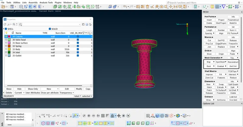
Column
3mm
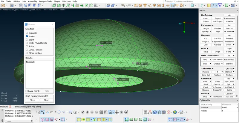
1mm
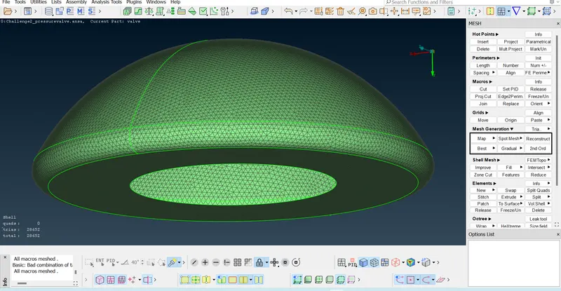
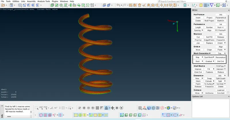
Spring meshing :-
5mm
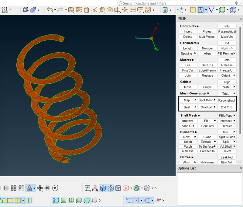
3mm
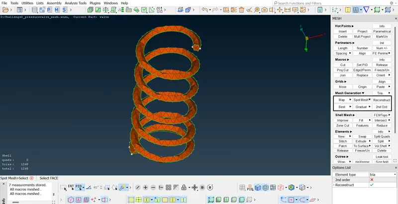
1mm
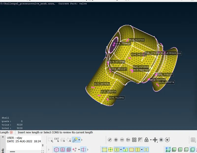
After completing the mesh on the entire model we can measure the distance between two nodes using 'measure' tool and can store the results.Click on 'Measure' - Nodes - select any two nodes - enter and then store the results.
ANSA file of Target length = 5mm
https://drive.google.com/file/d/1o12dTk0S0VeiBfjaLp8laHB0U-9TMW_e/view?usp=sharing
ANSA file of Target length = 3mm
https://drive.google.com/file/d/1IHj_8PaQJvcFW45ick1kv6F_6C_NzDmO/view?usp=sharing
ANSA file of Target length = 1mm
https://drive.google.com/file/d/1MIQS8fl1QREQIX1Kj_6bsyUs_j_5Jsxn/view?usp=sharing
Learning outcomes from this challenge:-
1. Finding the errors in geometry using 'Geometry checks', consturcting the missing parts/faces/surfaces using different functions under TOPO section.
2. Assigning PIDs, naming them and changing their colours.
3. Using mesh parameters, Quality criteria to set minimum and maximum target length.
4. Using OR,AND,Not,!Not,All & Invert functions.
5. Hiding faces,isolating the faces,Inverting the view of the model etc.
Conclusion :-
The surface meshing for the given pressure valve model is done using 3 different target lengths and we found that the one with lesser target length i.e target length = 1mm gives best refined meshing.Lesser the Target length greater will be the quality of the mesh.We have used the element type 'Tria'.Also we can use combinations of target lengths i.e for the planar and larger surfaces we can use higher target length but for the smaller surfaces or for some small helical surfaces like spring,coil etc. we have to use smaller mesh.