Week 2 Challenge : Surface meshing on a Pressure valve
WEEK 2 CHALLENGE: SURFACE MESHING ON A PRESSURE VALVE
Aim
For the given model, check for the geometrical errors and perform Topology cleanup accordingly. Set three different target lengths as three different cases and mesh the model.
Target length = 1mm, 3 mm and 5 mm (i.e. 3 cases) spring length 1mm (all cases)
Element type = Tria
Procedure
- First, we need to clean up the geometry from errors
- The errors were found through a checkup
- For cfd applications the solid should be sealed if the flow is internal as in our case
- So, the holes are closed with fill hole option for inlet and outlet and creating new faces
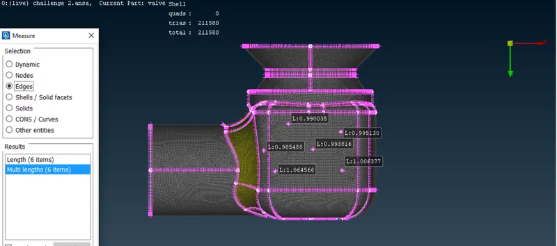
- As a next step i have removed the lines which are much closer than the mesh length to avoid difficulty in fitting the elements
- Then pid is are assigned carefully and they are termed as spring, column, valve head, body, inlet, outlet, outer case.
- Each pids are meshed separately for each case
- Target lengths are also assigned accordingly
Given Model
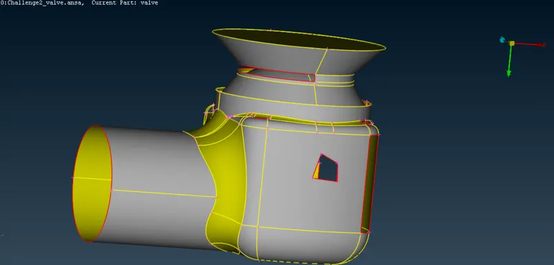
GEOMETRIC CLEAN UP
For meshing the model at first, we need to check the geometry of the model
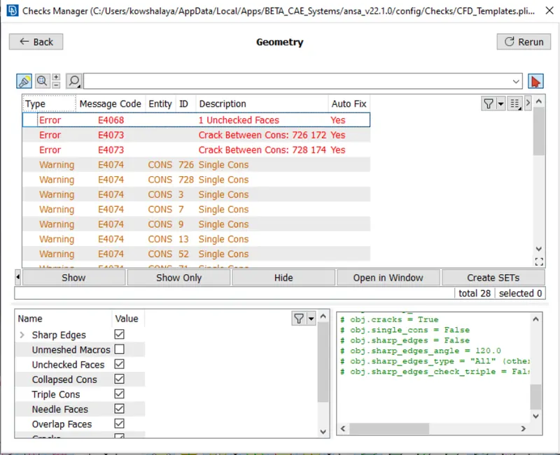
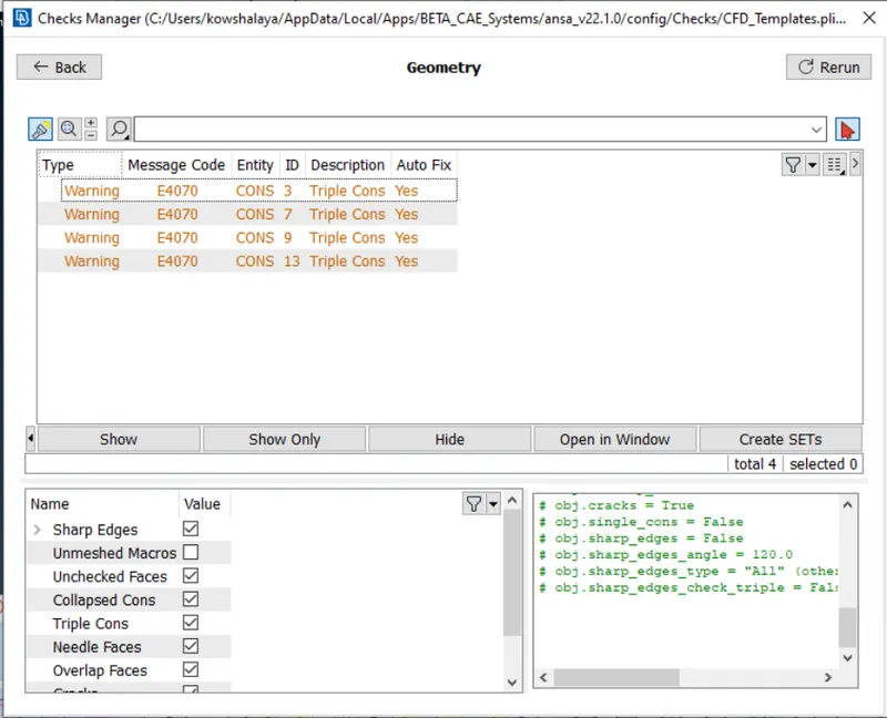
Here we have lot of errors regarding the uncovered faces and single coons we have to clear it up so we can go to the next step.
By using the CONS>>FILL hole option we can close some of the uncovered surface, cracks or faces
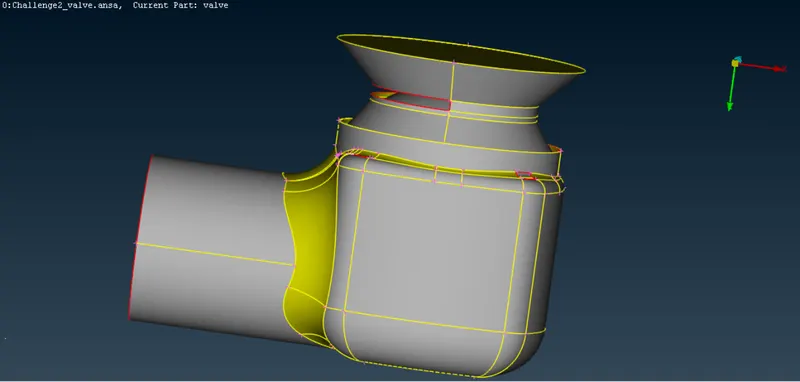
Here we can see that by using the fill hole tool we have covered the surface
In some cases (like curves) we have to use TOPO>>FACES>>NEW>>FITTED OR COONS
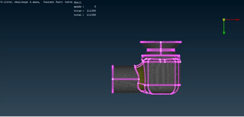
All the holes and the cracks have been cleared successfully.
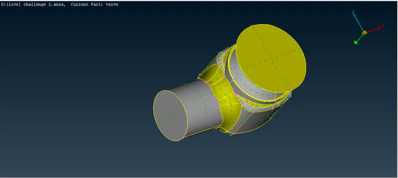
The warning is given for the triple cones formed at base so that’s not necessary.
Here we cleared all the geometrical cleanup successfully.
ASSIGNING NAMES FOR THE PID’S
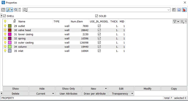
Here we have given 7 names for the PID’s respectively.
To give a name first we have to go to PID properties and select NEW>>SHELL PROPERTY option below and give the respective name for each PID’s and right click on the PID name and click apply and select the PID by left mouse button and click middle of the scroll bar thus the PID is assigned and you can see the glowing bulb in the PID property.
Case 1 (1mm)
After naming the PID’s next step is meshing
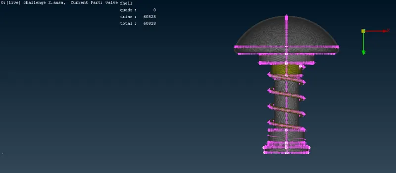
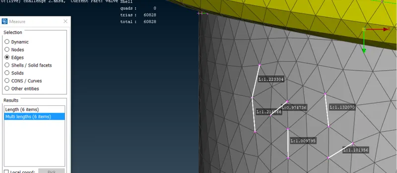
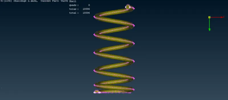
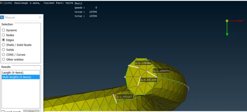
- Select the mesh option and give the length parameters as 1mm and macros also 1mm and select SPOT MESH>>visible
The meshed surface of outer region is shown
The inner part of the meshed surface
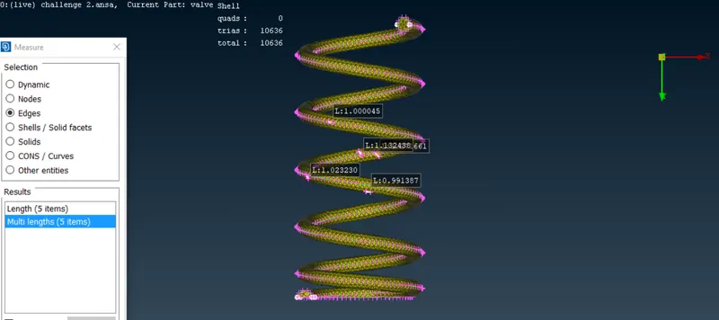
Spring
Case 2(3mm)
The outer surface of meshed pressure valve
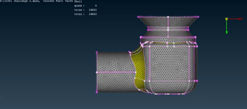
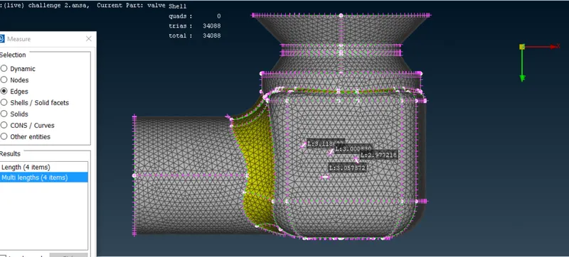
Inner surface of the pressure valve
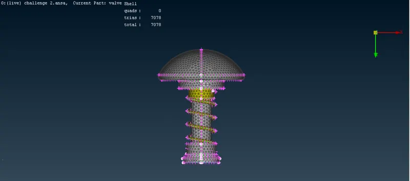
The spring length is given 1mm throughout all the cases because the spring is below 1.5mm
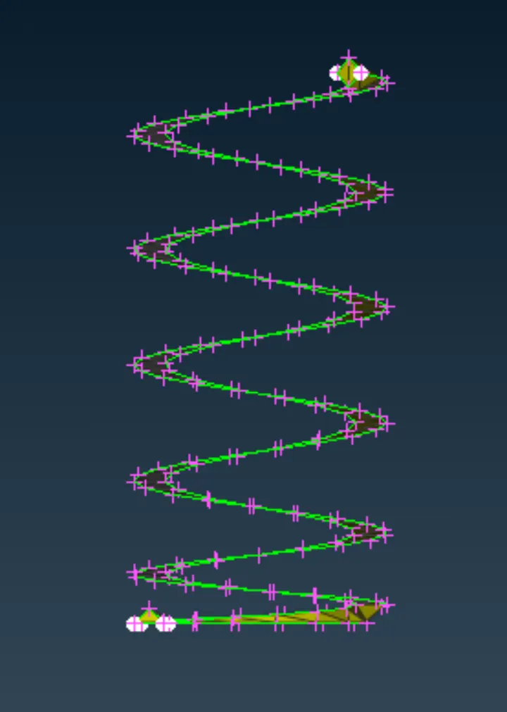
If we give higher length parameters to the spring the spring will have flattened surface. Mesh can’t be performed in this case so here given 1mm
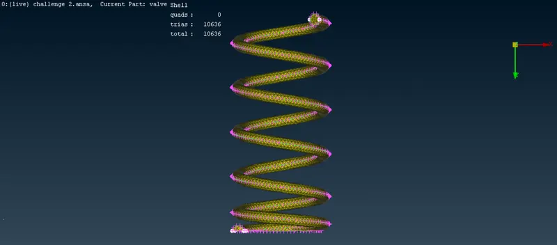
Case 3(5mm)
Outer surface
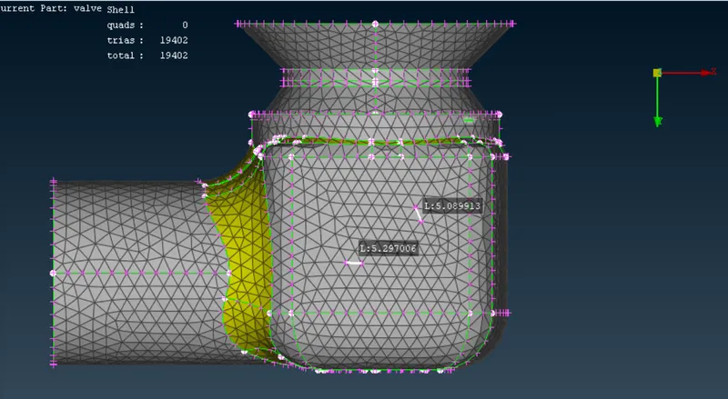
Inner surface
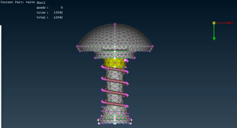
Spring
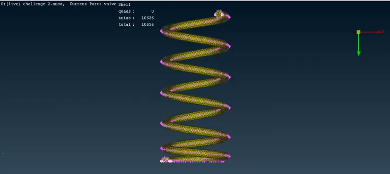
Learning outcomes
- Geometry checkup
- Topology cleanup
- Creating faces
- Filling holes
- Assigning PIDs
- Surface meshing complex geometry
Google drive link for the model
case 1- 1mm
https://drive.google.com/file/d/1paYXVPbxIhisLbrg1CvsZxLeTt3Dyjt4/view?usp=sharing
case 2 -3mm
https://drive.google.com/file/d/1YjlISKUZQ3WNWOGYEKjY9hb1jGpeLT4S/view?usp=sharing
case 3 - 5mm
https://drive.google.com/file/d/1PIG7kqnx4iGPsYQQ5juqC1FYvTG2Tdpr/view?usp=sharing