Week 2 Challenge
1. 1. How will you assign the Circular section to the column?
-
Open or Create the Model: Launch STAAD.Pro and open the existing model or create a new model in which you want to assign a circular section to a column.
-
Define Nodes and Elements: Define the nodes to represent the endpoints of the column, and then create the column element connecting these nodes. Ensure that the column element is connected correctly in the model.
-
Define Material Properties: Before assigning a circular section, you must define the column's material properties. In the "Properties" section of the STAAD.Pro interface, specify the material properties such as the Young's modulus, Poisson's ratio, density (if applicable), etc.
-
Define Circular Section Property: Now, you need to define the circular section property. In STAAD.Pro, section properties are defined separately from material properties. To do this, go to the "Sections" tab in the property grid or dialog box (usually located on the left-hand side of the STAAD.Pro interface).
-
Choose Circular Section: In the section properties dialog box, select the option to create a circular section. You will typically be prompted to enter the diameter or radius of the circular section.
-
Assign Circular Section to the Column: After specifying the diameter or radius, choose the column element to which you want to assign the circular section. STAAD.Pro will then apply the circular section property to the selected column.
Open Staad Pro> Geometry> Define Node> (0,0,0) and (0,y=10,0)
Connect node using node cursor.
Then add a circular section to that beam using the above steps.
1. 2. How will you assign the Unit system to a .std model file?
When you start a new project in STAAD.Pro, you'll be prompted to define the basic settings for the model, including the unit system. Follow these steps:
- Open STAAD.Pro and start a new project.
- In the "New Project" dialog, choose the desired unit system from the "Unit System" drop-down menu. The available options typically include metric (SI) and imperial (US Customary) systems with various unit options (e.g., kN/m, kN/cm, lbs/ft, lbs/in, etc.).
- Click "OK" to create the new model with the selected unit system.
If you already have a model in STAAD.Pro and want to change the unit system, follow these steps:
- Open your existing STAAD.Pro model.
- Go to the "Setup" menu and select "Units".
- In the "Unit System" dialog, choose the desired unit system from the drop-down menu.
- Click "OK" to apply the changes to the model. Note that this action may prompt you to convert the existing data to the new unit system, so make sure to review the changes before confirming.
1. 3. What are the parameters to be specified while using “Bay Frame” option?
To create a model using Bay Frame option Go to Structural Wizard> Bay Frame
Then specify the below-desired Values>
- Model Name
- Length
- Height
- Width
- Number of Bays along the length
- Number of Bays along the Width
1. 4. Name few codal standards incorporated in STAAD Pro software?
- For steel the codal provision are IS 800, IS 800:2007 LSD, IS 800:2007 WSD
- For the concrete the codal provision is IS-456:2000
- For Seismic IS 13920 and IS-1893 :2016
- For Wind Load - IS 875 part 3
1. 5. How will you specify the design compressive strength for a RCC section?
Go to the design option > Click on the define parameter > In the design parameter the FC (compressive strength) of RCC section is given as 30000 kN/m2.
2. 1. State the “Input” steps involved in RCC design?
-
Modeling Geometry:
- Create nodes: Define the coordinates of the nodes that represent the structural points (corners, intersections, etc.).
- Create members: Connect the nodes to form structural members (beams, columns, slabs, etc.).
- Assign member properties: Specify the cross-sectional properties of the members, such as dimensions and reinforcement details.
-
Material Properties:
- Define concrete material properties: Specify the concrete grade and relevant properties like compressive strength, tensile strength, modulus of elasticity, etc.
- Define steel material properties: Specify the steel grade and properties like yield strength, modulus of elasticity, etc.
-
Loads:
- Apply dead loads: Assign self-weight of the structure, including concrete, steel, and other permanent loads.
- Apply live loads: Assign imposed loads, such as occupancy, furniture, etc.
- Apply other loads: Add additional loads like wind loads, seismic loads, etc., depending on the design requirements.
-
Support Conditions:
- Define support conditions: Specify how the structure is supported, such as fixed, pinned, roller, etc.
-
Load Combinations:
- Create load combinations: Define various load combinations (e.g., DL+LL, DL+WL, DL+EL) per the relevant design codes.
-
Analysis Settings:
- Define analysis type: Choose the type of analysis (e.g., static, dynamic) based on the structural behavior and design requirements.
- Specify analysis parameters: Set analysis options like load factors, tolerance, and solver preferences.
-
Design Codes:
- Select design codes: Choose the appropriate design code(s) that apply to your project and location.
-
Design Preferences:
- Set design preferences: Define various design parameters, such as factors of safety, concrete cover, minimum reinforcement, etc.
-
Perform Analysis:
- Run the analysis: Execute the structural analysis to obtain internal forces and reactions.
-
RCC Design:
- Perform RCC design: STAAD.Pro will perform the necessary calculations based on the chosen design codes and parameters to check the member capacities and reinforcement requirements.
-
Review Results:
- Review design results: Check the design results for each member, including reinforcement details, utilization ratios, and any design warnings or errors.
-
Post-Processing:
- Generate reports: Generate design reports, including detailed calculation sheets and graphical representations of the design results.
2. 2. Explain the difference between Fixed and Enforced support conditions in STAAD Pro?
-
Fixed Support Condition:
- When a node is assigned a "Fixed" support condition in STAAD.Pro, it means that the node is fully fixed, and its displacements in all translational and rotational degrees of freedom are constrained to be zero.
- Translation: The node cannot move in the X, Y, and Z directions.
- Rotation: The node cannot rotate about the X, Y, and Z axes.
- Effect: Nodes with fixed support conditions act as rigid connections or immovable supports. They resist any applied forces or deformations and do not allow any movement or rotation.
-
Enforced Displacement Support Condition:
- The "Enforced Displacement" support condition is used to impose specified displacements on a node, allowing for partial constraints.
- Translation: You can individually enforce specified displacements in the X, Y, and Z directions. Enforcing a displacement value will impose that value on the node, while leaving it as "Free" will allow the node to move freely in that direction.
- Rotation: Similarly, you can enforce specified rotations about the X, Y, and Z axes. Enforcing a rotation value will impose that rotation on the node, while leaving it as "Free" will allow the node to rotate freely.
- Effect: Enforced displacement support conditions are useful for modeling partial restraints or support with certain degrees of freedom fixed to specific values. This is commonly used for modeling supports with translational or rotational restrictions, such as pinned connections or supports with specific displacements.
3. 1. Explain the steps involved in the analysis of a model using STAAD Pro sequentially.
Analyzing a model in STAAD.Pro typically involves the following steps:
-
Model Creation: The first step is to create a digital representation of the structure you want to analyze. This involves defining the geometry, supports, loads, and material properties. You can create the model using the graphical user interface (GUI) of STAAD.Pro.
-
Geometry Definition: Define structural elements like beams, columns, slabs, etc., by specifying their dimensions, coordinates, and other relevant properties. This step involves creating a 3D representation of the structure.
-
Support Conditions: Assign appropriate boundary conditions or supports to the structural elements to mimic real-world behavior. For example, you can specify fixed supports, pinned supports, rollers, etc., based on how the structure is anchored or connected to the ground or other parts of the structure.
-
Material Properties: Assign material properties to the structural elements, such as concrete, steel, etc. You will need to provide properties like elastic modulus, density, Poisson's ratio, and other relevant material parameters.
-
Loading: Apply various loads that the structure will experience during its service life. These loads can include dead loads, live loads, wind loads, seismic loads, temperature loads, etc. You need to specify the magnitude, direction, and distribution of each load.
-
Load Combinations: Define load combinations based on relevant design codes or standards. Different combinations of loads are considered to assess the structure under different scenarios, ensuring safety and stability.
-
Analysis: After setting up the model with all the necessary inputs, perform the structural analysis. STAAD.Pro uses numerical methods to solve the complex equations governing the behavior of the structure under the applied loads. It calculates the internal forces, moments, displacements, reactions, and other response parameters for each element in the model.
-
Results Verification: Review and validate the analysis results to ensure they are reasonable and consistent with the behavior of the actual structure. Check for convergence, stability, and any warning messages that could indicate issues with the model or its inputs.
-
Post-Processing: STAAD.Pro provides various tools to visualize and interpret the analysis results. You can view deformed shapes, diagrams, contour plots, and other graphical representations to understand the behavior of the structure under different load conditions.
-
Design (Optional): Depending on your objectives, you may choose to perform design checks for the structural members. STAAD.Pro can also assist in the design process by verifying whether the members are meeting the required design code specifications or not.
-
Documentation: Finally, create comprehensive reports documenting the model details, analysis results, and any design checks performed. These reports are crucial for project documentation and communication with other stakeholders.
3. 2. Explain the two ways in which a structural framework/model can be created in STAAD Pro software.
In STAAD.Pro software, there are two main ways to create a structural framework or model:
-
Graphical User Interface (GUI): The graphical user interface is the most common and user-friendly method for creating a structural model in STAAD.Pro. It allows engineers to interact with the software through a visual interface. Here's how it works:
a. Define Geometry: You can start by creating the geometry of the structure by drawing lines, arcs, and other shapes to represent beams, columns, slabs, etc. The software provides tools to create nodes (points where elements connect) and then use those nodes to define the structural members.
b. Assign Properties: After creating the geometry, you need to assign properties to the structural elements. These properties include material properties (e.g., steel, concrete) and cross-sectional properties (e.g., section type, dimensions).
c. Set Support Conditions: You can specify the support conditions for each node in the model, such as pinned supports, fixed supports, rollers, etc. This step is crucial as it simulates how the structure is connected to the ground or other supporting elements.
d. Apply Loads: Once the geometry and supports are defined, you can apply various loads to the model, such as dead loads, live loads, wind loads, etc. STAAD.Pro provides a range of load types and options for load application.
e. Run Analysis: After completing the model setup, you can run the analysis within the GUI. The software will perform the necessary calculations to determine the internal forces, reactions, and displacements of the structure under the applied loads.
f. Results and Post-Processing: Once the analysis is complete, you can visualize and interpret the results using graphical tools. STAAD.Pro offers various post-processing options, including deformed shapes, diagrams, and contour plots, to help you understand the behavior of the structure.
-
Using Text Input Files (Editor Mode): The second method involves creating the structural model using text-based input files. In this mode, you write the model data and commands in a text editor, and then you can execute the input file within STAAD.Pro. Here's how it works:
a. Define Geometry and Properties: You manually write the input commands to define the geometry of the structure, and specify element properties, node coordinates, and other relevant data.
b. Set Support Conditions and Loads: Similar to the GUI method, you need to specify support conditions and apply loads by writing the corresponding commands in the input file.
c. Run Analysis: Once the input file is ready, you can execute it within STAAD.Pro and the software will perform the analysis based on the provided input commands.
d. Results and Post-Processing: After the analysis is complete, you can review the results through the GUI, just like in the graphical mode. The post-processing options are the same, allowing you to visualize and interpret the analysis results.
3. Elaborate the different support conditions in STAAD Pro.
i) FIXED - All the transitional and rotational displacement are restrain
ii) PINNED- Transitional displacement is restrained but rotational moments are not restrained
iii) FIXED BUT- The fixed but support is similar to pinned support it allows us to provide the degree of freedom to view the displacement either translation or rotational.
iv) ENFORCED- When enforced supports are assigned to the structure the software allows the springs to themselves and the displacement can be calculated however there is no provision to provide the spring constant.
v) ENFORCED BUT- The software assigns the spring itself with zero stiffness or high stiffness.
3. 4. How will you extract the stress distribution for a staircase slab?
Firstly define the nodes in the staircase design
Then add beams >
Then add the Support condition >
Add material properties, add plate/solid to represent the staircase slab >
Define and assign load and load cases accordingly >
click the Analysis command and add the preferred type of analysis >
Run the analysis >
After the analysis Go to post-processing Mode and click on plate result click on plate stress and then one new tab will appear. after that click on Maximum absolute stress >
The final result of plate stress.
3. 5. Explain the different ways to view SFD & BMD in STAAD Pro.
- i) After completion of the design the STAAD Pro will automatically provide the BMD and SFD
- ii) By entering the post-processing process, click on OK
- iii) By clicking the beam results in a deflection command
- iv) Reaction click the beam deflection.
- v) Click on Annotate - select Max BM so you can see the value.
- vi) We see the SFD and BMD graphically also
- vii) For that Click on Layout - Select Graph - You can see the SFD and BMD graphically too.
Practical
1. Analyze the following structural elements and validate the results
A. Simply Supported Beam
a. A Simply supported beam with two point loads symmetrically placed
b. Span L = 20m
c. Load P = 50kN each
d. Both P located at 5m from each support
open Staad pro Software and create new model
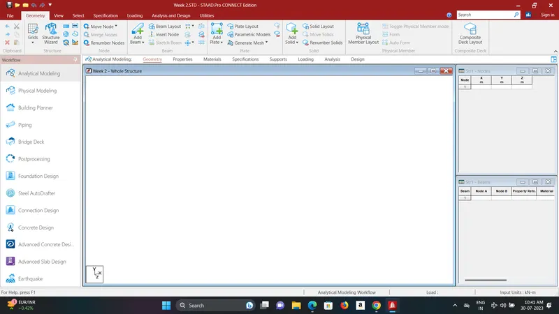
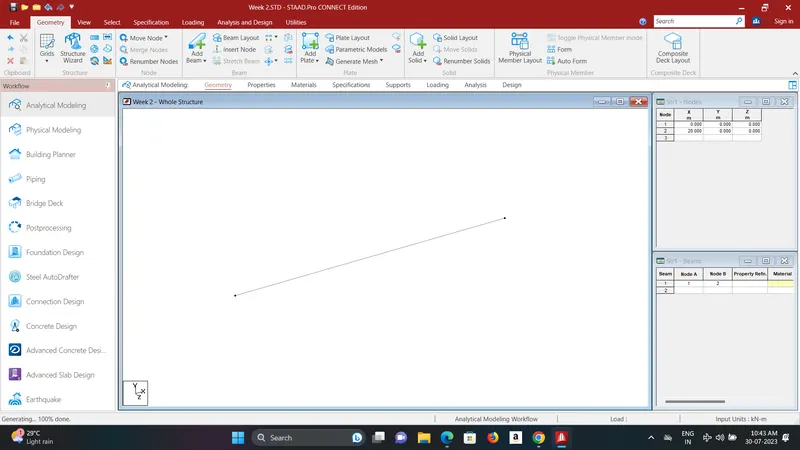
add node and beam of length 20m.
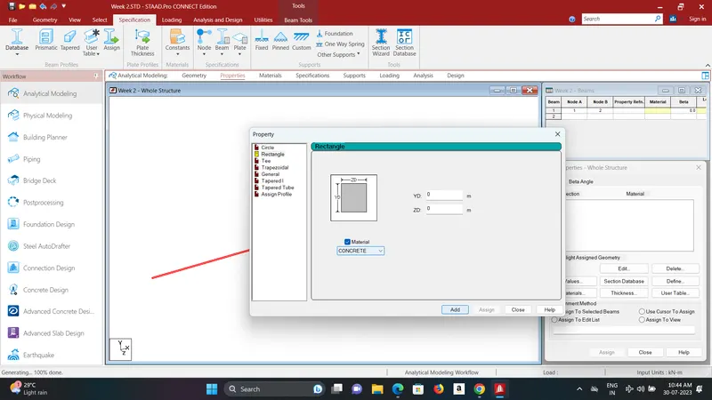
add bead specification > Concrete
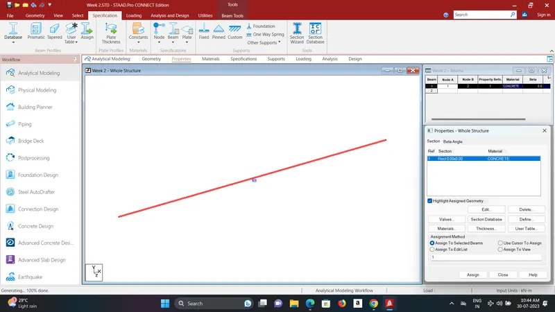
add Pined support and add to model.
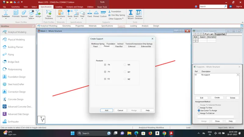
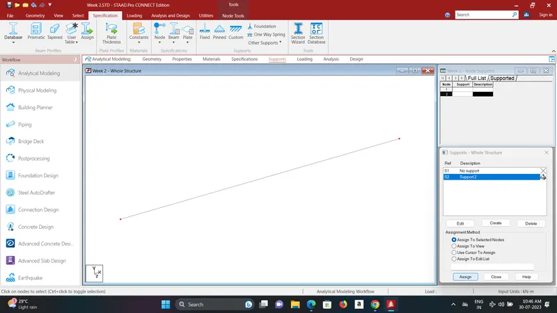
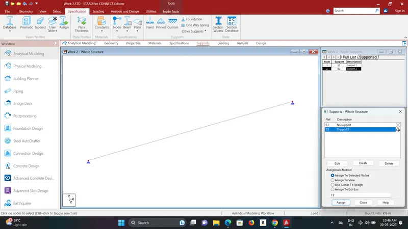
Then add load cases.
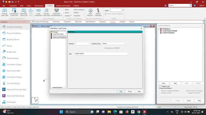
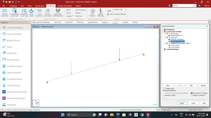
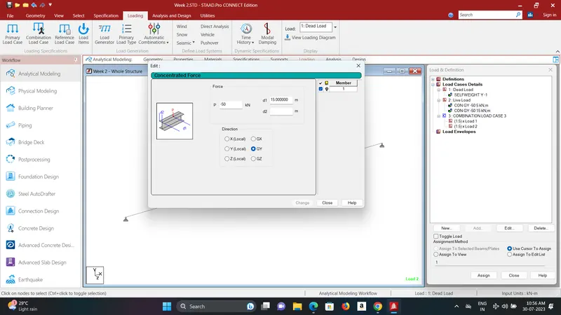
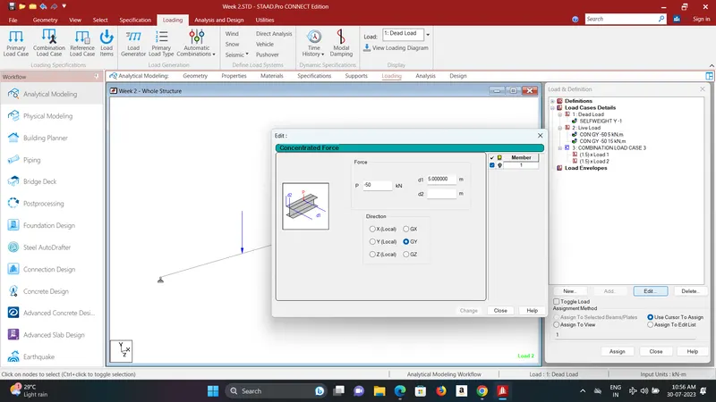
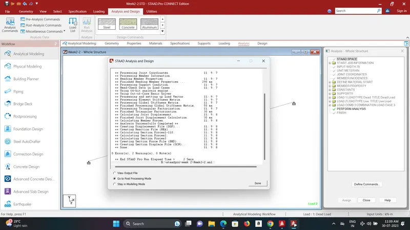
perform Analysis.
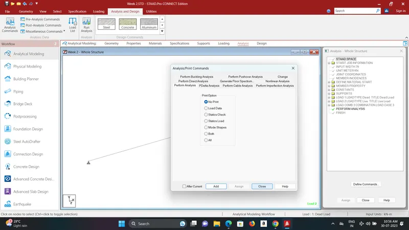
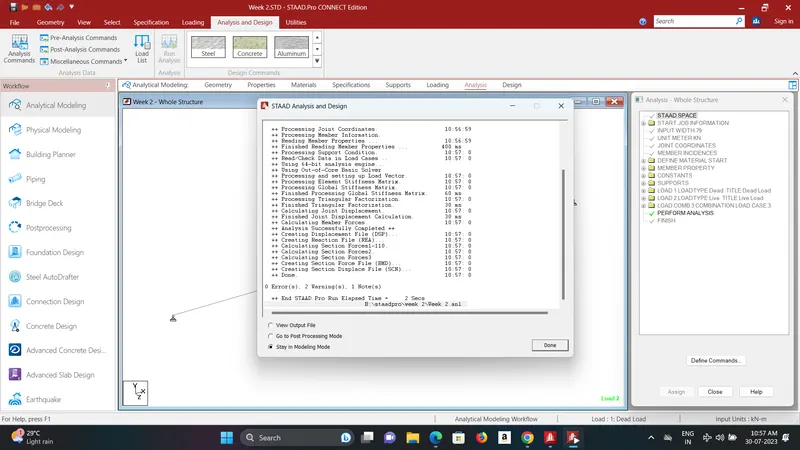
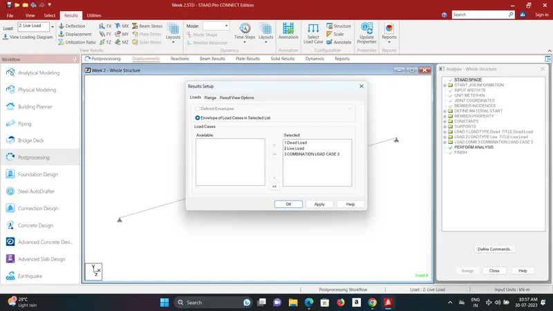
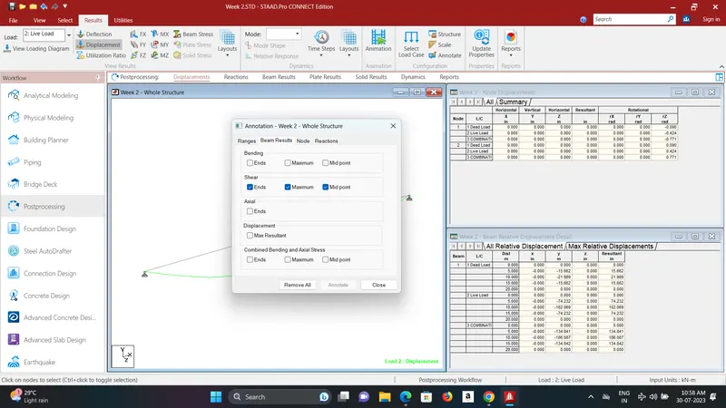
Results-
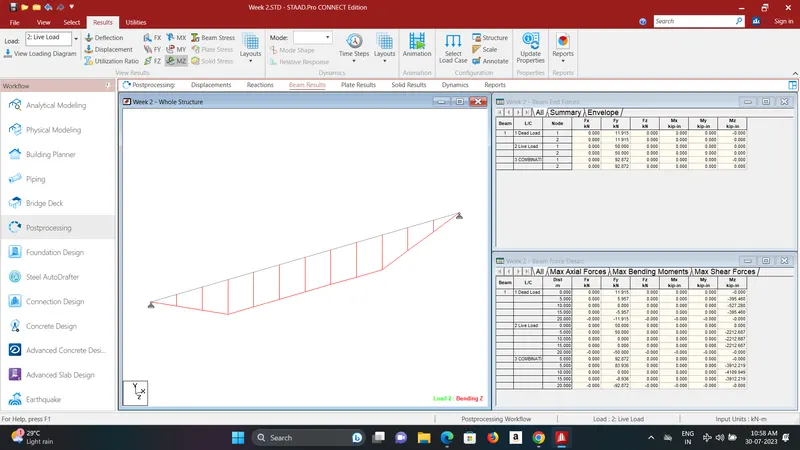
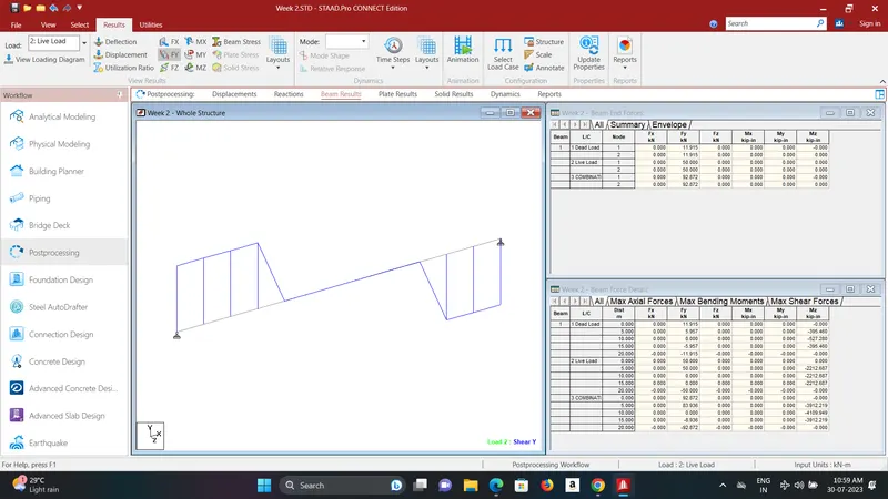
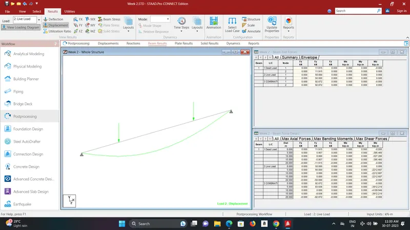
B.Fixed Beam
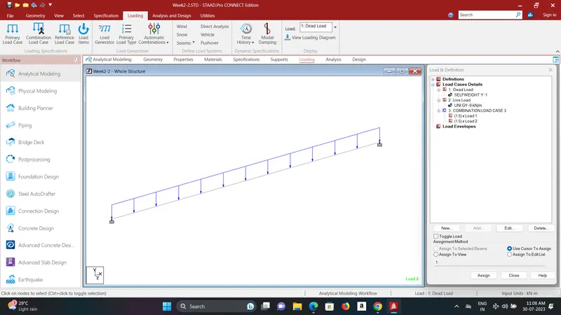
a. Span L = 16m
b. Uniformly Distributed Load w=9kN/m
Creat New model.
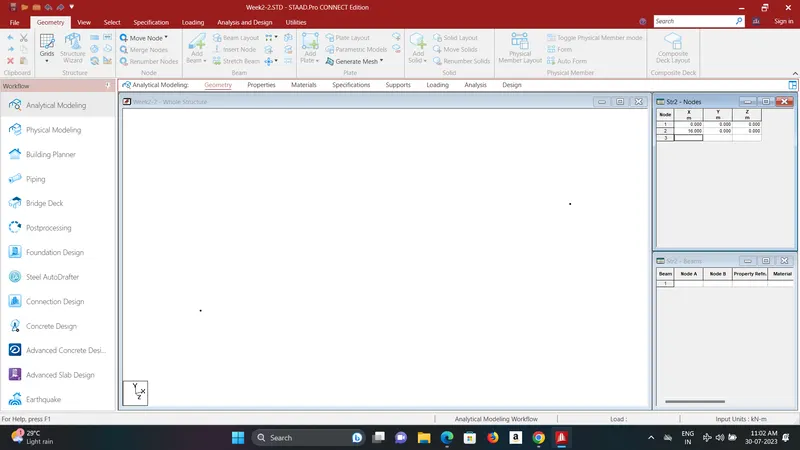
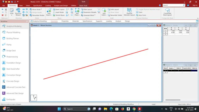
add Node and Beam to the model. Spacing 16m
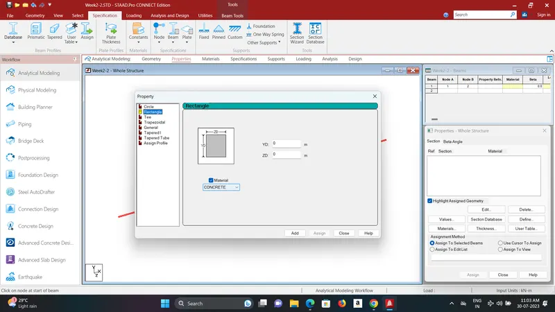
add properties to the beam.
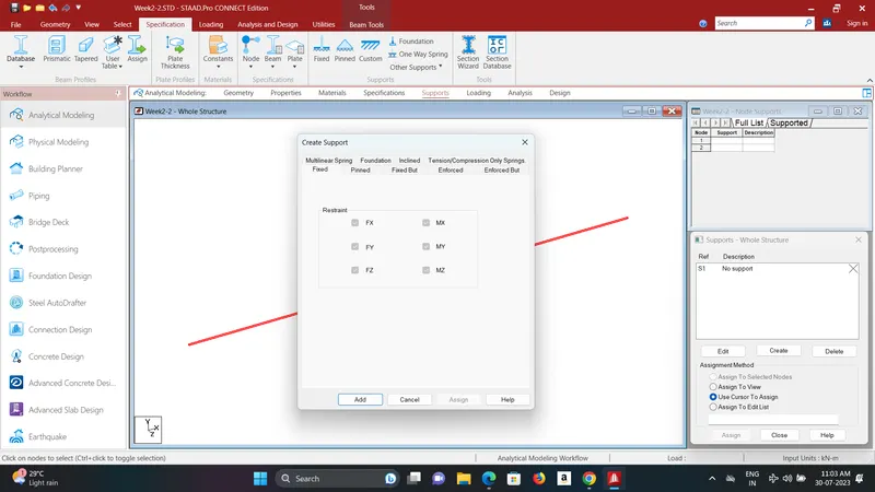
add fixed supports.
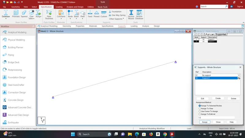
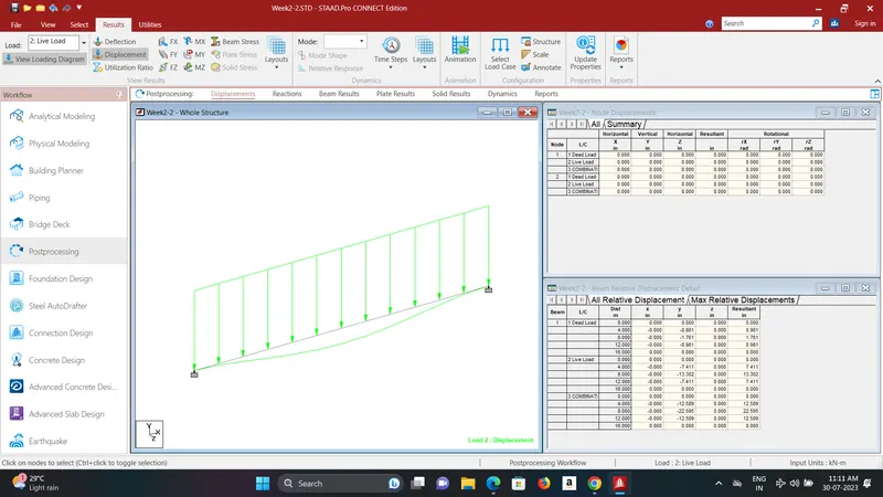
add Self weight Dead Load and Live load > Member Load > Uniformed Force = -9KN
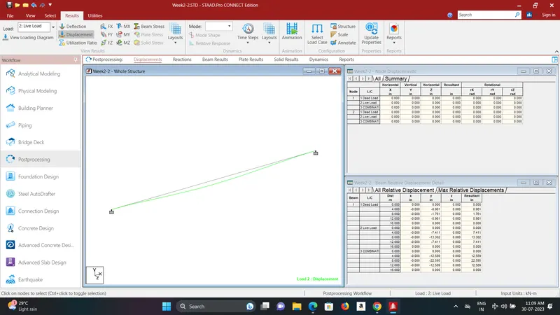
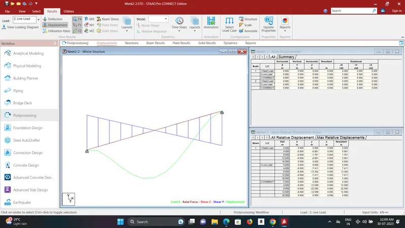
Performe Analysis
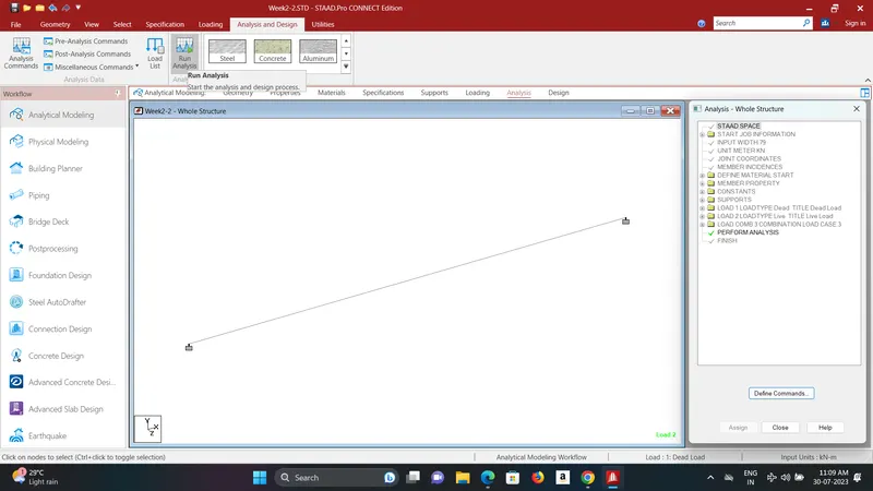
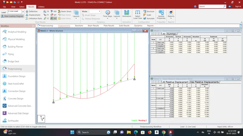
Result-