Week 1 Challenge
1.1. Write the steps involved to upload a .std file through webmail?
ans-
-Access your webmail: Open your preferred web browser and go to the website of your email service provider (e.g., Gmail, Outlook, Yahoo Mail).
-Attach the .std file: Look for an attachment icon (usually represented by a paperclip) within the email composition window. Click on the icon to open the file selection dialog.
-Locate and select the .std file: Navigate through your computer's file system to find the .std file you want to upload. Click on the file to select it, and then click on the "Open" or "Choose" button to attach it to the email.
-Verify attachment: Ensure that the .std file appears as an attachment within the email. You may see the filename listed below the subject line or a visual representation of the attachment icon.
-Review and send: Double-check the recipient details, subject, message, and attachment to make sure everything is accurate. If you're satisfied, click on the "Send" or "Send Email" button to send the message with the attached .std file.
1.2. Name the different materials that can be designed using STAAD Pro?
Materials that can designed using Staad pro are-
- Concrete
- Steel
- Aluminium
- Timber
- Composite sections
- Masonary
1.3. Is it possible to capture images in STAAD Pro? If yes how?
Yes, STAAD Pro does have built-in capabilities to capture images directly within the software. STAAD Pro is primarily a structural analysis and design software focused on creating and analyzing 3D models of structures. It provides various tools and features for modeling, analyzing, and designing structures, but it does include functionality for capturing images or screenshots within the software itself.
Utilities>Take Picture
Access the "Take Picture" feature: In the menu bar, go to "Utilities" and then select "Take Picture." Alternatively, you can use the keyboard shortcut "Ctrl+P."
1.4. Name the three ways by which you can create a model?
In STAAD.Pro, there are three primary methods for creating a structural model:
a. Graphical User Interface (GUI)
b. Import from CAD Software
c. Text Editor/Scripting
These three methods provide flexibility in creating models in STAAD.Pro, catering to different user preferences and requirements. You can choose the most suitable approach based on your familiarity with the software, the complexity of the structure, and the available data sources.
1.5. Write the steps followed to assign properties in a model?
-Open the model: Either create a new model or open an existing model file (.std) in STAAD.Pro by using the "File" menu and selecting "Open" or by using the keyboard shortcut "Ctrl+O."
-Select elements: Use the appropriate selection tools (e.g., select by clicking, select by window) to choose the elements to which you want to assign properties. Elements can include beams, columns, slabs, walls, etc.
-Access the property assignment: In the STAAD.Pro interface, locate the "Properties" tab or menu. The specific location may vary depending on the version of STAAD.Pro you are using.
-Assign properties to selected elements: In the "Properties" tab or menu, you will find various properties that can be assigned to the selected elements. These properties may include section properties, material properties, support conditions, load assignments, etc. Select the appropriate property type to assign.
2.1. Name any six design parameters involved in RCC design?
The six Design parameters involved in RCC design are as below;
- Clear cover
- FC compressive strength of concrete
- FY Tensile Strength of steel
- Main and Sub Dia of the bar including stirrups
- Code of practice
- End concrete design/Fabrication shuttering details
2.2. What are the different cursor types available in STAAD Pro?
- Nodes cursor
- Plates cursor
- Beams cursor
- Plates and Solid cursor
- Loads cursor
- Solids cursor
- Physical Member cursor
- Geometry cursor
2.3. How will you generate different views for a model? State the steps involved.
When the model has been analyzed, you can generate different views to visualize and interpret the results. The most common views include:
a. 3D View: This provides a three-dimensional perspective of the entire structure, showing all elements and their positions in 3D space.
- Isometric view
b. Plan View: A plan view represents the structure from the top, showing the layout of beams, columns, and slabs.
- Top view
- Bottom view
c. Elevation View: Elevation views display the structure from the sides, showing the vertical arrangement of elements.
- Front view
- Left view
- Right View
- Back view
d. Section Views: Section views cut through the structure to reveal the internal details, such as reinforcement in beams and columns.
e. Shear Force and Bending Moment Diagrams: Generate diagrams that show how shear forces and bending moments vary along the length of beams and columns.
f. Deformed Shape: Display the deformed shape of the structure under the applied loads to understand the magnitude of displacements.
2.4. Explain the procedure to define a “Simply Supported” condition in STAAD Pro?
For a "Simply Supported" condition, you need to set different supports at each end of the beam. Typically, the two supports required for a simply supported beam are:
- click on create support command
- There we can get options like fixed support, pin support, Roller, etc.
a. Pin Support: This support prevents translation (movement) in all directions but allows rotation. It represents a hinge-like connection and is used for one end of the simply supported beam.
b. Roller Support: This support allows translation along one direction but restricts movement in the other two directions and rotation. It is used for the other end of the simply supported beam.
Place the pin support at one end of the beam and the roller support at the other end. You can do this by clicking on the respective nodes of the beam ends or selecting the appropriate support types from a dropdown menu.
2.5. Name any five topics that you will include while creating DBR.
DBR- Design Brief Report
- Geographical location and specification of the project
- Structural Layout
- work plan and Construction schedule
- QA and QC procedure
- Estimation
2.6. Describe the term “Multi-material design” of STAAD Pro?
- It is used for 3D model generation, analysis, and multi-material design.
- The STAAD.Pro supports several steel, concrete, and timber material in a separate member
- This separate member will coordinate and then formed into a structure.
-
Material Properties: Users can define the properties of different materials used in the structure, such as concrete compressive strength, steel yield strength, modulus of elasticity, Poisson's ratio, etc.
-
Element Types: STAAD.Pro supports a variety of structural element types, such as beams, columns, slabs, walls, and more. Engineers can assign specific materials to each element based on the type of material used in construction.
-
Composite Sections: The software allows the creation of composite sections, which are sections formed by combining different materials. For example, a composite beam may have a steel section on top and a concrete section at the bottom.
-
Design Codes: STAAD.Pro provides access to various international design codes and standards that govern the design of structures with different materials. Users can select the appropriate design code based on the project location and requirements.
-
Design Optimization: The software can optimize the sizes of structural elements based on the applied loads and material properties. It helps ensure that the structure is designed efficiently and cost-effectively.
-
Analysis of Composite Behavior: STAAD.Pro can analyze the interaction between different materials in a composite section. For example, it can consider the composite action between a steel beam and a concrete slab in a composite floor system.
-
Design Reports: After performing the multi-material design analysis, STAAD.Pro generates comprehensive design reports that include the design results and details for each material type and structural element.
3.1. Name the structure systems in STAAD Pro? Explain each system.
-
Frame System: The frame system is one of the most commonly used structure systems in STAAD.Pro. It consists of interconnected beams and columns that form a 3D frame. Frame elements are used to represent the members of the structure, and they are connected at their nodes to create a structural framework. Frame systems are suitable for modeling structures like buildings, bridges, and industrial facilities.
-
Truss System: The truss system represents a structure composed entirely of truss elements. Trusses are lightweight and efficient load-bearing systems made up of straight members connected at joints. They are commonly used for structures with long spans, such as roofs, bridges, and towers, where a lightweight and rigid framework is required.
-
Grid System: The grid system is a combination of beams and columns forming a regular grid pattern. It is often used for modeling slabs or floor systems of buildings. The grid system allows for easy definition of uniform structural elements in both horizontal and vertical directions.
-
Plate/Shell System: The plate/shell system is used to model structures with thin, planar elements, such as slabs and walls. In STAAD.Pro, plate elements represent these thin surfaces, and they can be used to model flat plates, curved shells, or folded plates.
-
Wall System: The wall system is designed specifically for modeling walls in buildings. It allows engineers to model walls of different thicknesses and orientations, which is essential for analyzing the lateral load resistance and stability of buildings.
-
Space Frame System: The space frame system is used to model three-dimensional truss-like structures with interconnected members forming a spatial grid. Space frames are often used for large-span roofs, long bridges, and other complex architectural designs.
-
Slab System: The slab system is used for modeling flat, horizontal floor or roof slabs in buildings. Slab elements are typically used in conjunction with other structural systems like frames or grids to represent the complete building structure.
3.2. Explain the coordinate system adopted in STAAD Pro software.
The coordinate system that is adopted in STAAD Pro software is X, Y, and Z coordinates.
So basically the co-ordinate system adopted in STAAD Pro software is:
- Global Axis:- Mainly global axis are fixed in the coordinate system.
- Local Axis:- Local axis is variable in nature. We can change the local axis but not the global axis.
-
Global Coordinate System: The global coordinate system is the main reference frame used to define the entire structure. It is a right-handed Cartesian coordinate system with three axes: X, Y, and Z. The X-axis is typically oriented along the length of the structure, the Y-axis along the width, and the Z-axis vertically, representing the upward direction. The origin (0,0,0) of this global coordinate system is often set at a specific location on the ground or at a reference point within the structure.
-
Local Coordinate System for Elements: Each individual structural element (e.g., beams, columns, slabs) in the model has its local coordinate system. This local coordinate system is defined relative to the global coordinate system. It helps specify the orientation of the element with respect to the global axes.
-
Node Coordinates: The coordinates of each node in the model are defined with respect to the global coordinate system. A node represents a point in space where structural elements are connected. The coordinates of nodes are expressed as (X, Y, Z) values, which define their position relative to the origin of the global coordinate system.
-
Load and Load Cases: When applying loads to the structure, their direction and magnitude are often defined in the global coordinate system. This ensures that loads are correctly oriented and applied to the appropriate elements.
-
Results and Analysis Output: The results obtained from structural analysis in STAAD.Pro, such as displacements, internal forces, and moments, are also presented in the global coordinate system. This allows engineers to interpret the results easily and understand the behavior of the structure in its actual orientation.
3.3. Elaborate DBR and its uses.
A brief report on a design (DBR) project's main needs, goals, and restrictions is known as a design brief report. It acts as a starting point for designers, engineers, or other creative professionals to comprehend the project's scope and direct their work toward satisfying the needs and expectations of the customer. The form and content of a design brief report typically look like this:
-
Project Overview
-
Project Objectives
-
Target Audience
-
Scope of Work
-
Constraints and Limitations
-
Design Inspirations and Guidelines
-
Functional and Technical Requirements
-
Deliverables
-
Timeline and Milestones
-
Budget
-
Approval Process
-
Contact Information
3.4. Explain the different types of analysis options in STAAD Pro.
- Linear Elastic Analysis
- P-Delta analysis
- Buckling analysis
- Pushover analysis
- Dynamic Analysis
- Buckling Analysis
- Non-linear analysis
- Foundation/Rcc/CC/Steel Structure analysis
3.5. Explain the difference between Fixed and Fixed But conditions.
Fixed condition:-
Fixed condition in the STAAD Pro software is the condition where all the degrees of freedom that is horizontal or vertical or moment are fixed or we can say these conditions are restrained we cannot change accordingly. Those conditions we can say are fixed conditions.
Fixed-But condition:-
And as for the fixed-end condition, we can say that this condition can be customized its end conditions accordingly. In this condition, we can change the end condition it is not restrained. We can release some of the required degrees of freedom.
Practical
1. Create a STAAD Model with the following Specification
a. A beam of span 16m
b. Support : Fixed on one end and Roller support(Horizontal) on the other end
c. A point load of 50 kN at the mid-point
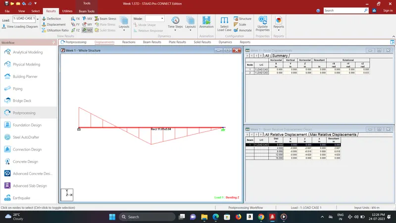
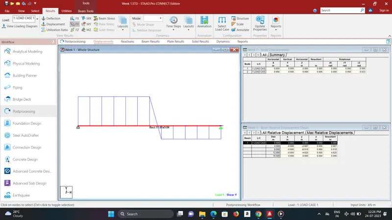
d. Draw SFD and BMD using software
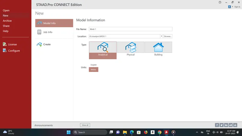
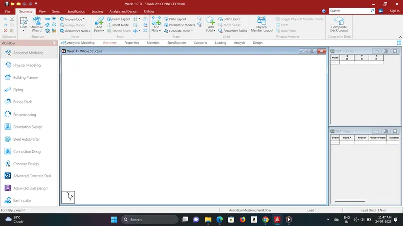
Open staad pro > Enter Job details and Model type
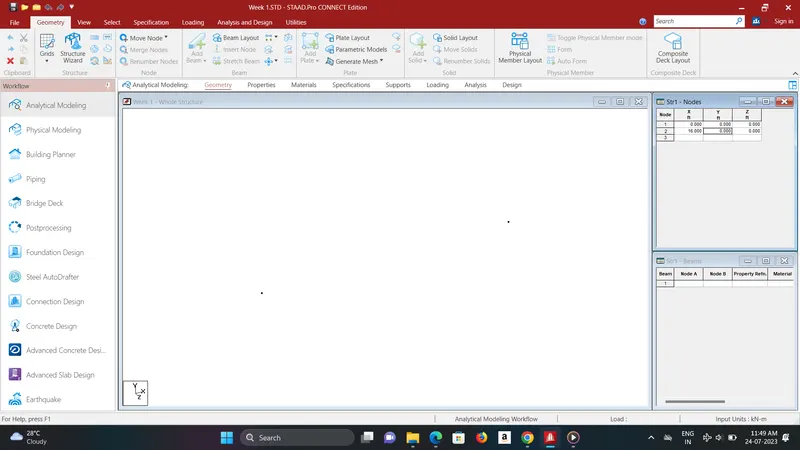
To make beam it need to enter 2 points or node
for that go to Geometry Tag and Specify co-ordinates of 2 points in form of X,Y,Z.
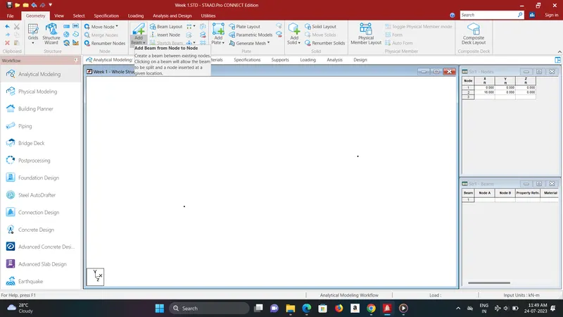
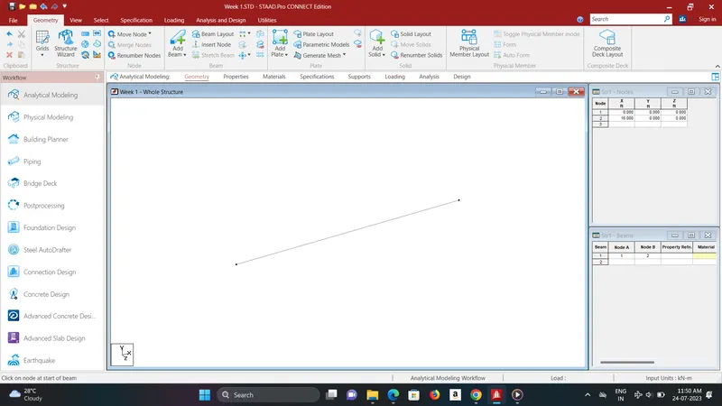
Then add beam using the ADD BEAM Tool.
To add support go to Support TAB.
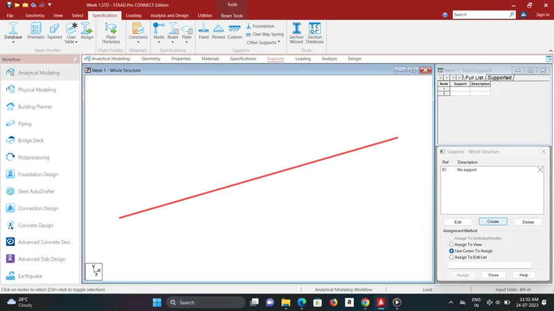
Creat 2 supports for both ends.
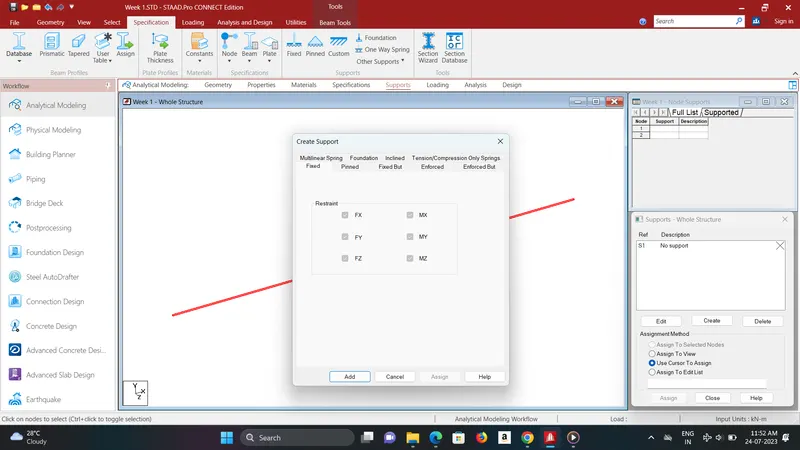
fixed
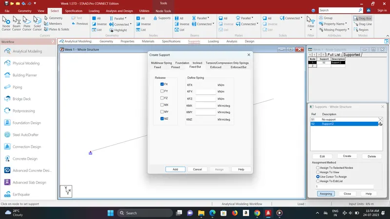
Fixed for X direction and Rollor.
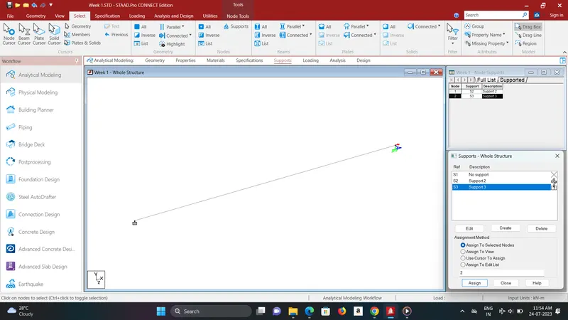
Then Assign using tool -"Assign to selected nodes".
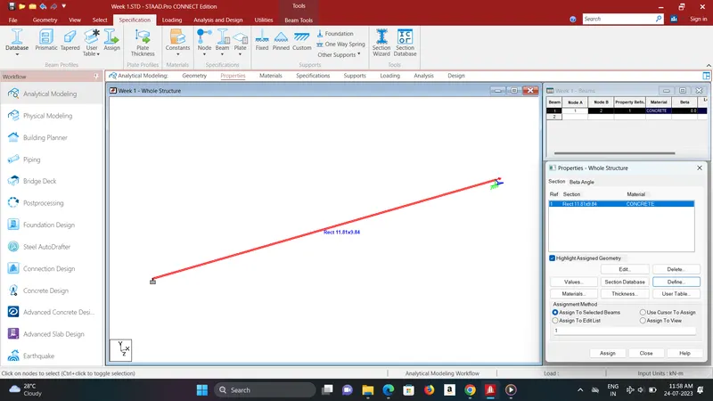
Add property to the beam as Concrete.
Assign Load > Load Cases> Dead Load add> Member Load
Specify value as -50KN and distance 8m from one end
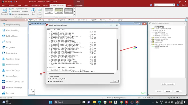
Then specfy load Analysis method from Design and analysis panel.
Result Window-