Week 2 Challenge
Aim:
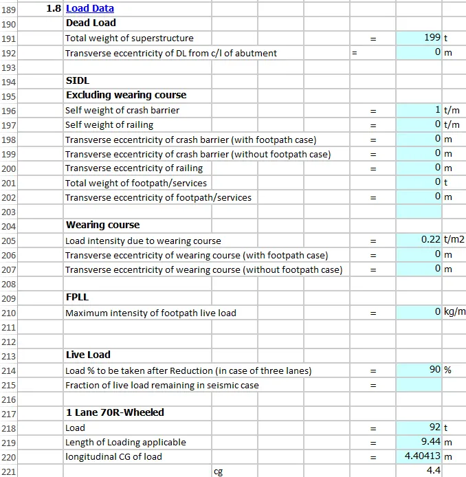
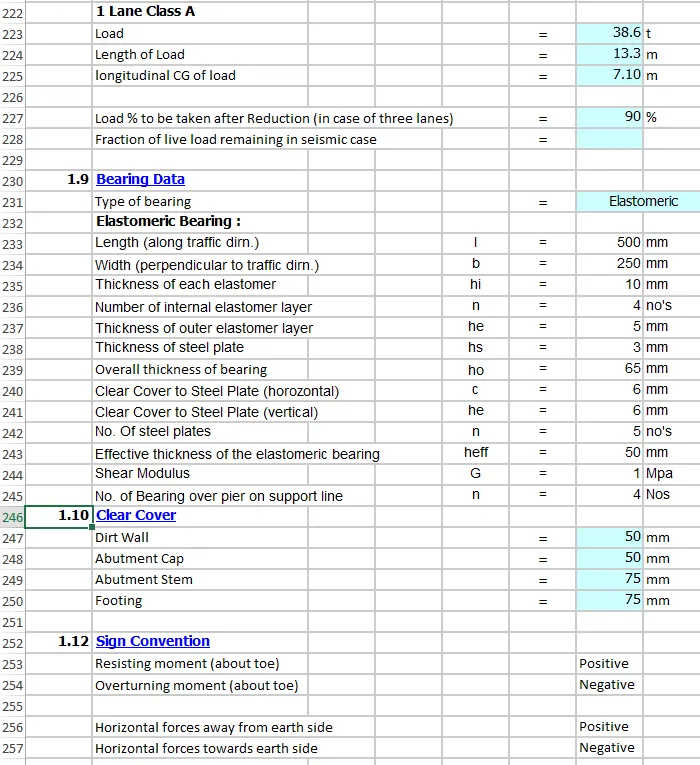
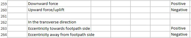
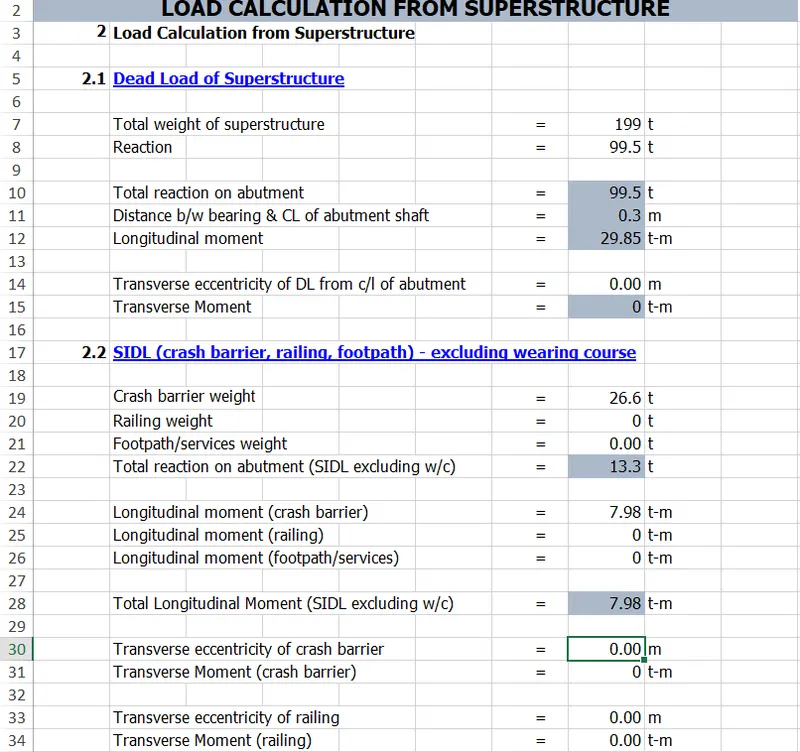
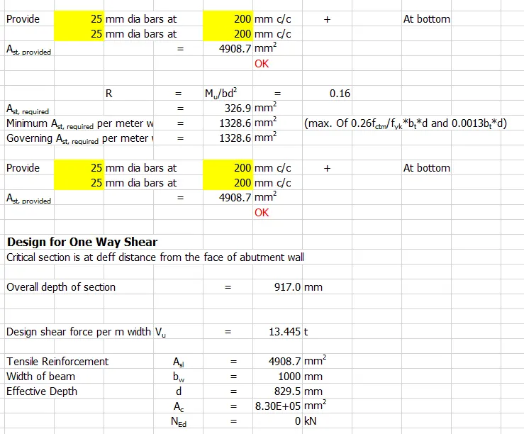
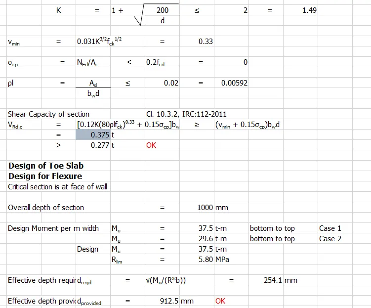
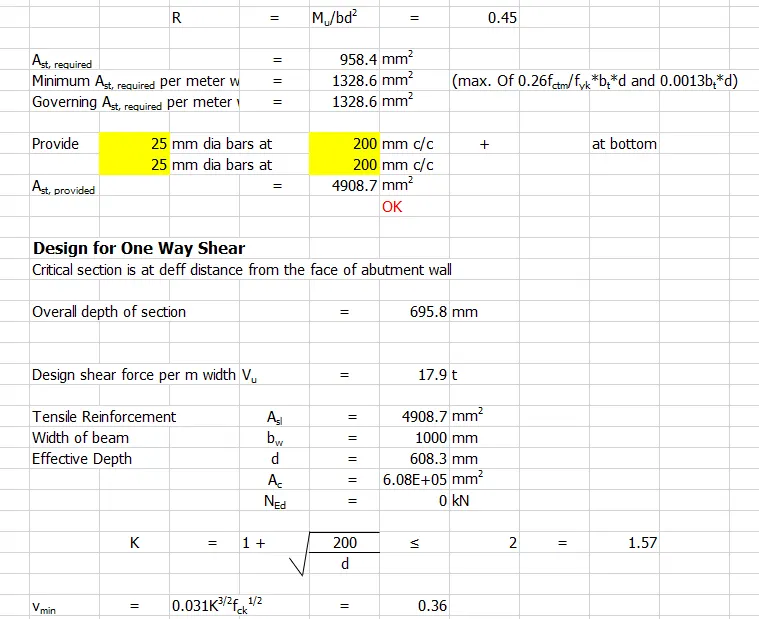
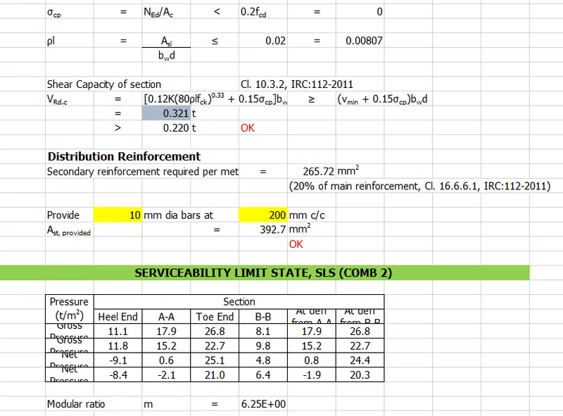
1.To define all loads to be applied in the abutment of the bridge as per IRC 6 clauses and check overturning and sliding and design the section of stem, heel and toe. Also show the detailing of the steel in the foundation and wall.
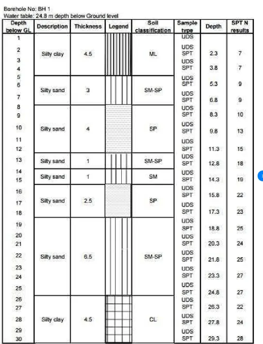
2.To decide the boreholes location and its depth of exploration in case of shallow foundation. To identify all the parameters we need to get from the site/geotechnical investigation for design of the foundation. List different type of soils/rock (minimum 5) and what criteria should be followed for the shallow foundations for selecting the foundation level, their characteristics and collect a picture of each. Draw a typical borehole showing all the data.
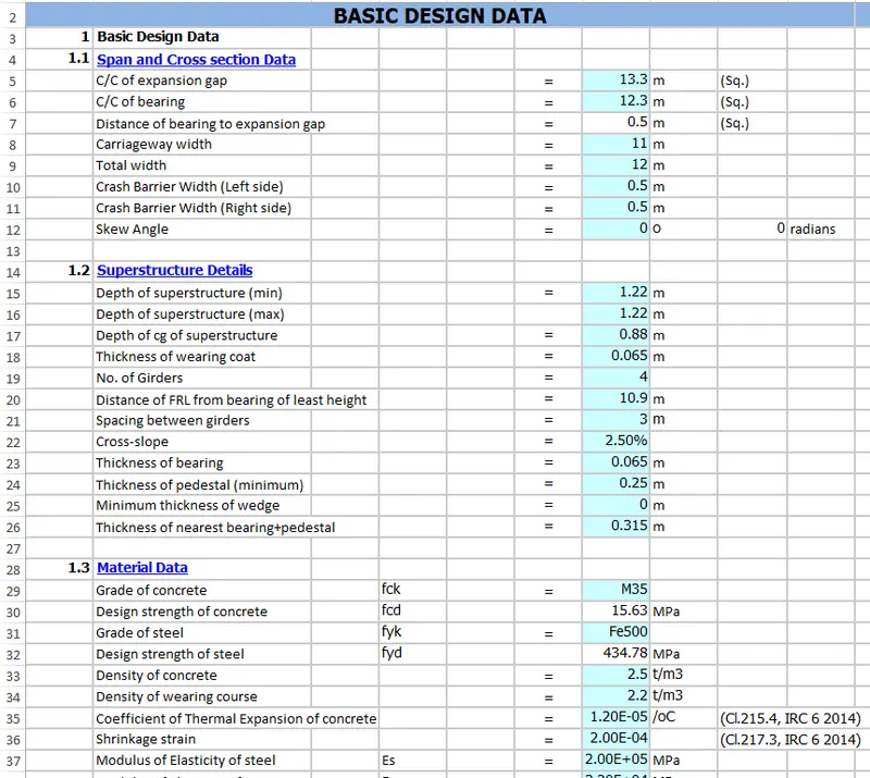
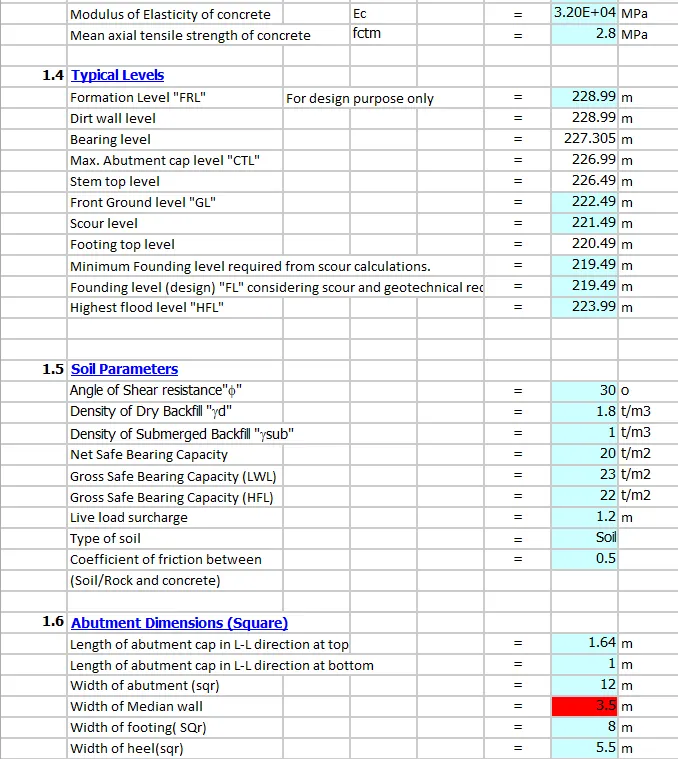
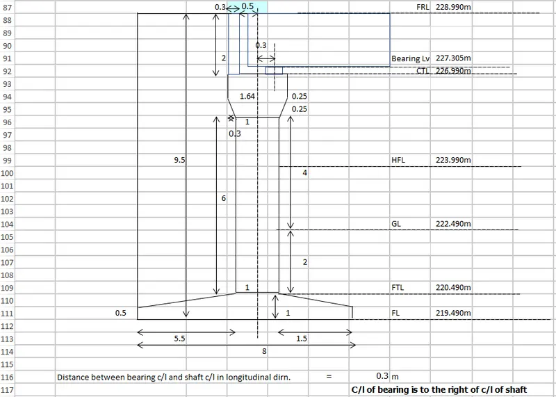
Introduction: Height of Abutment is 4 m (from ground level), embedded 2 m ground. SBC = 200 kN/m2 (Eccentricity from bearing and abutment center is 0.3 m ). Use coefficient of friction =0.5. Soil density =18 kn/m3.
Procedure:
Dead load - IRC 6 2017 CL.203
The dead load carried by a girder or member shall consist of the portion of the weight of the superstructure and the fixed loads (SIDL) carried thereon like wearing course, crash barrier, footpath and railing which is supported wholly or in part by the girder or member including its own weight. Also self weight of substructure (bearing, pier, pier cap), foundation and backfill weight comes under dead load.
Live Load - IRC 6 2017 CL.204
For bridges the design live load shall consist of standard wheeled or tracked vehicles or trains of vehicles as illustrated in Figs. 1, 2 & 4
and Annex A or Special Vehicle (SV) as per Clause 204.5, if applicable. The trailers attached to the driving unit are not to be considered as detachable.
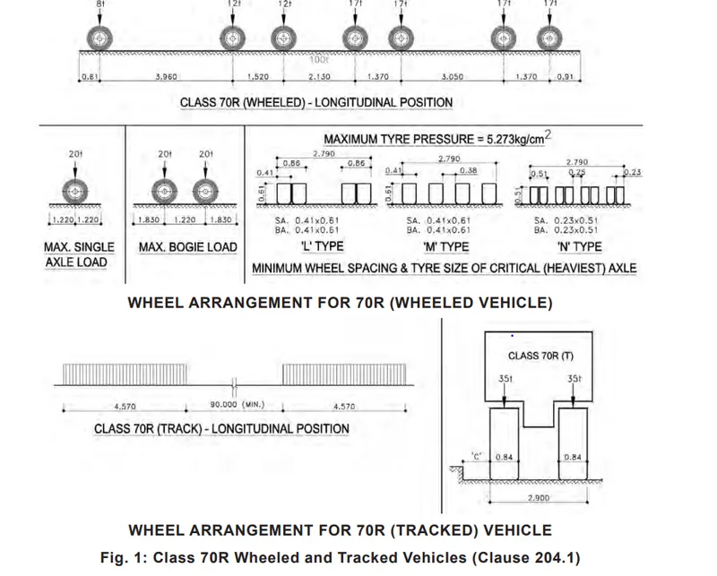
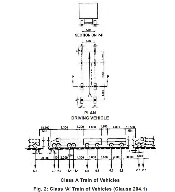
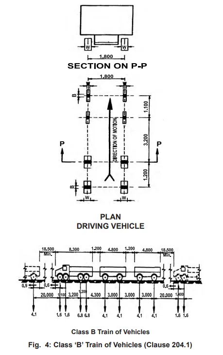
Combination of above wheel/tracked loads are used for design as follows:
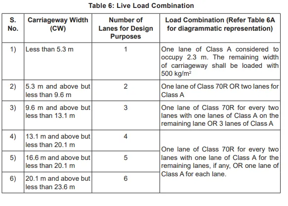
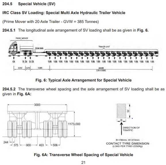
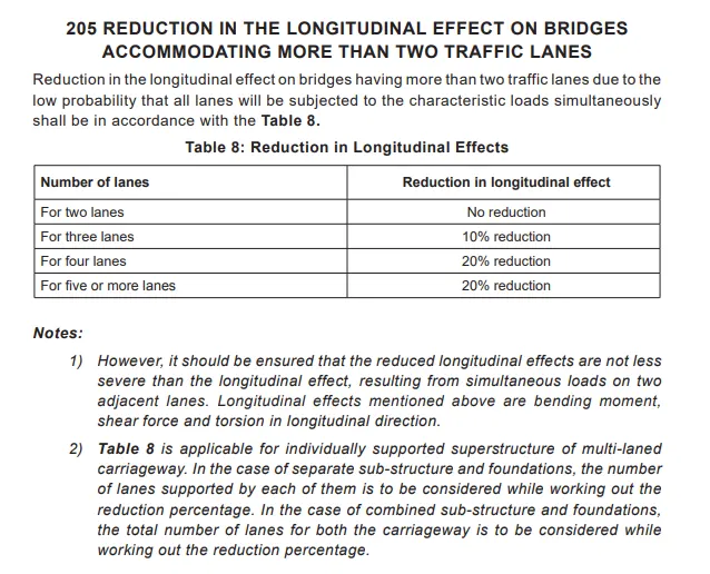
Reduction of live load is done as per clause 205 of IRC 2017 as follows
Footpath Live Load (FPLL) - IRC 6 2017 CL.204
If footpath is present - For all parts of bridge floors accessible only to pedestrians and animals and for all footways the loading shall be 400 kg/m2. For the design of foot over bridges the loading shall be taken as 500 kg/m2
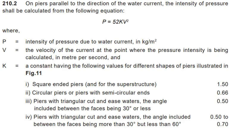
Horizontal forces due to Water current - IRC 6 2017 CL.210
Any part of a road bridge which may be submerged in running water shall be designed to sustain safely the horizontal pressure due to the force of the current.
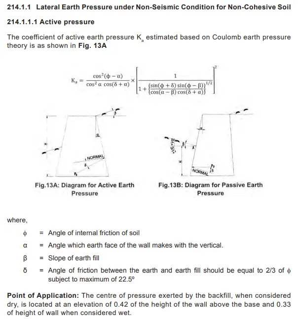
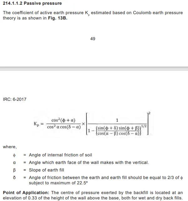
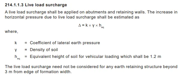
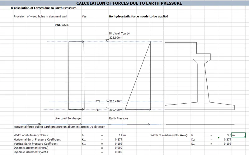
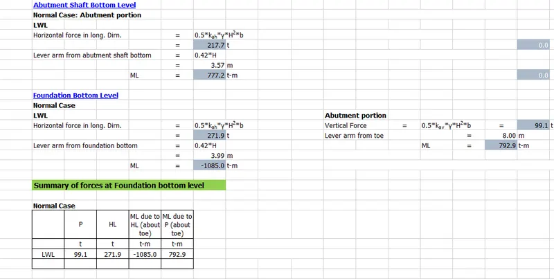
Earth pressure - IRC 6 2017 CL.214
Structure designed to retain earth fills shall be proportioned to withstand pressure calculated in accordance with any rational theory. Coulomb’s theory shall be acceptable for non-cohesive soils. For cohesive soil Coulomb’s theory is applicable with Bell’s correction. For calculating the earth pressure at rest Rankine’s theory shall be used.
Buoyancy in HFL case - IRC 6 2017 CL.213
In the design of abutments, especially those of submersible bridges, the effects of buoyancy shall also be considered assuming that the fill behind the abutments has been removed by scour. To allow for full buoyancy, a reduction shall be made in the gross weight of the member affected by reducing its density by the density of the displaced water.
Note:
1) The density of water may be taken as 1.0 t/m3
2) For artesian condition, HFL or actual water head, whichever is higher, shall be considered for calculating the uplift.
In the design of submerged masonry or concrete structures, the buoyancy effect through pore pressure may be limited to 15 percent of full buoyancy.In case of submersible bridges, the full buoyancy effect on the superstructure shall be taken into consideration.
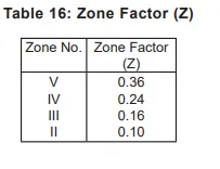
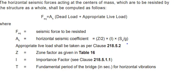
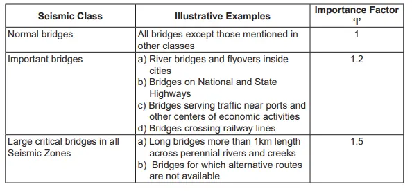
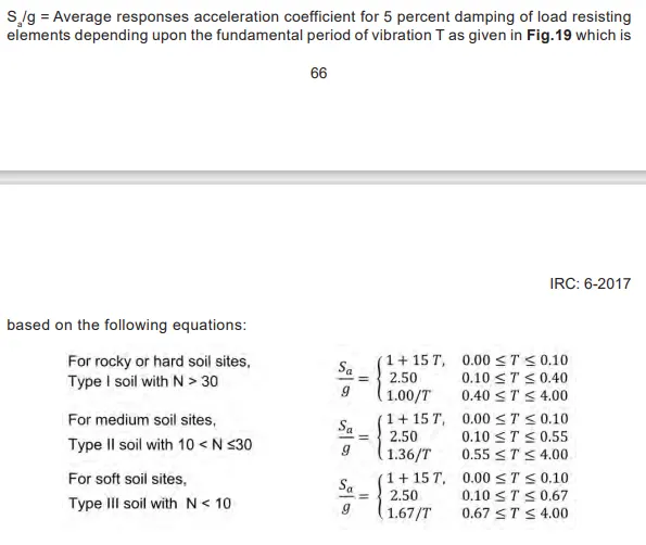
Seismic Load - IRC 6 2017 CL.218
Seismic Zone considered as per Map

Wind load is not considered as it is not governing.
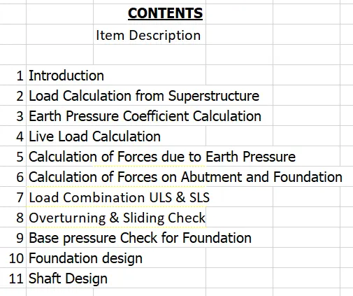
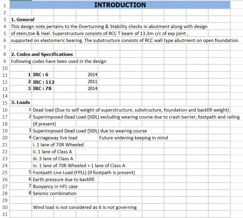
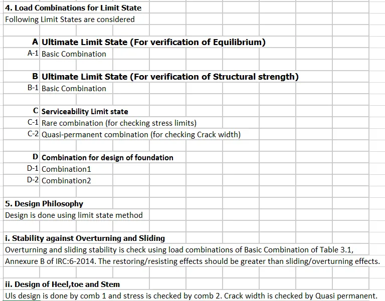
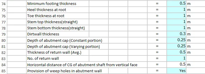
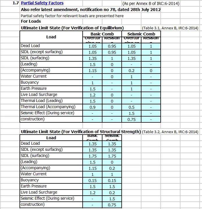
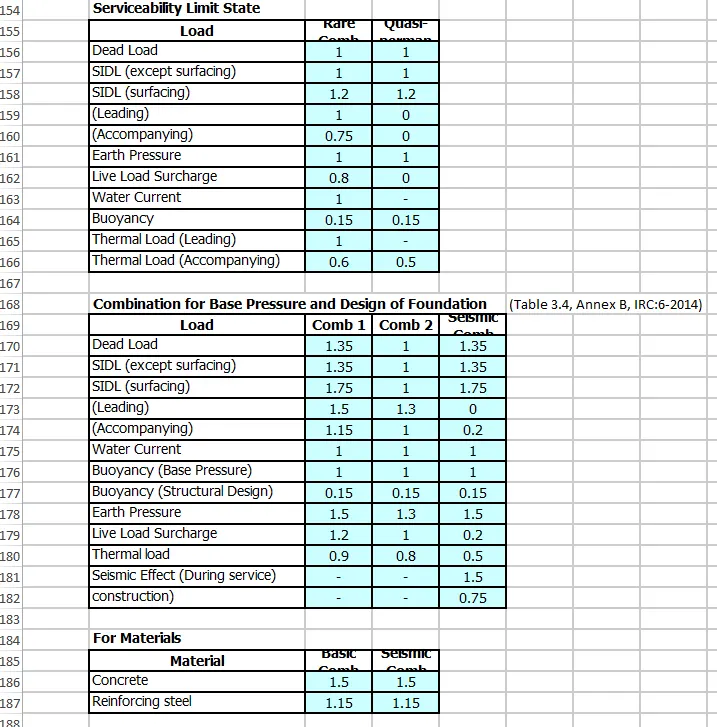
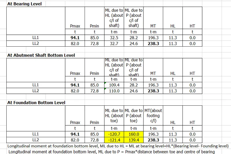
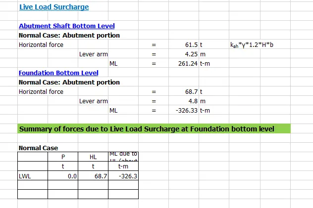
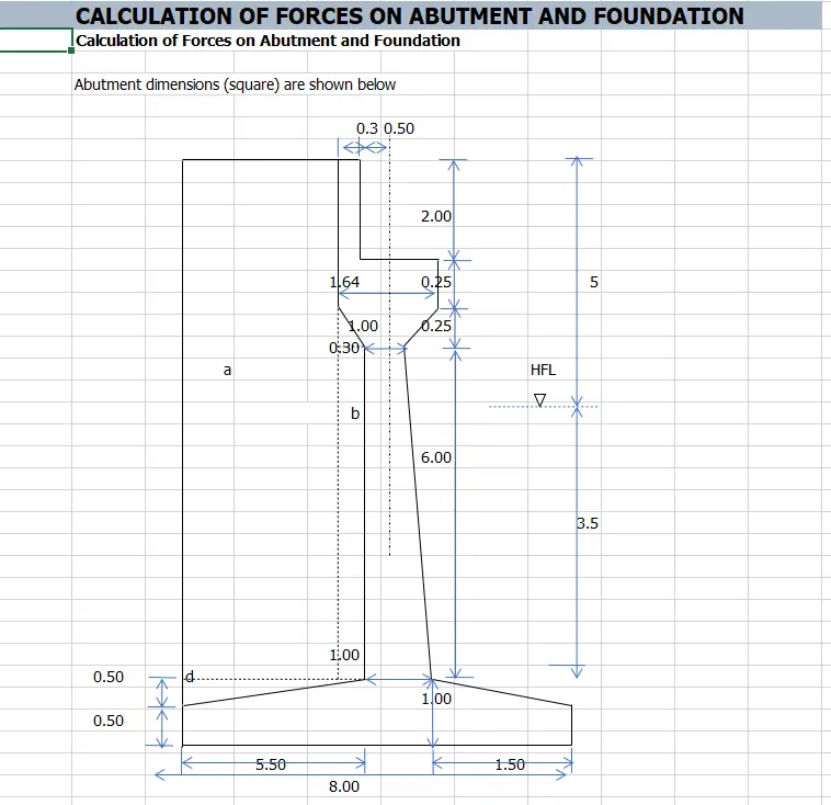
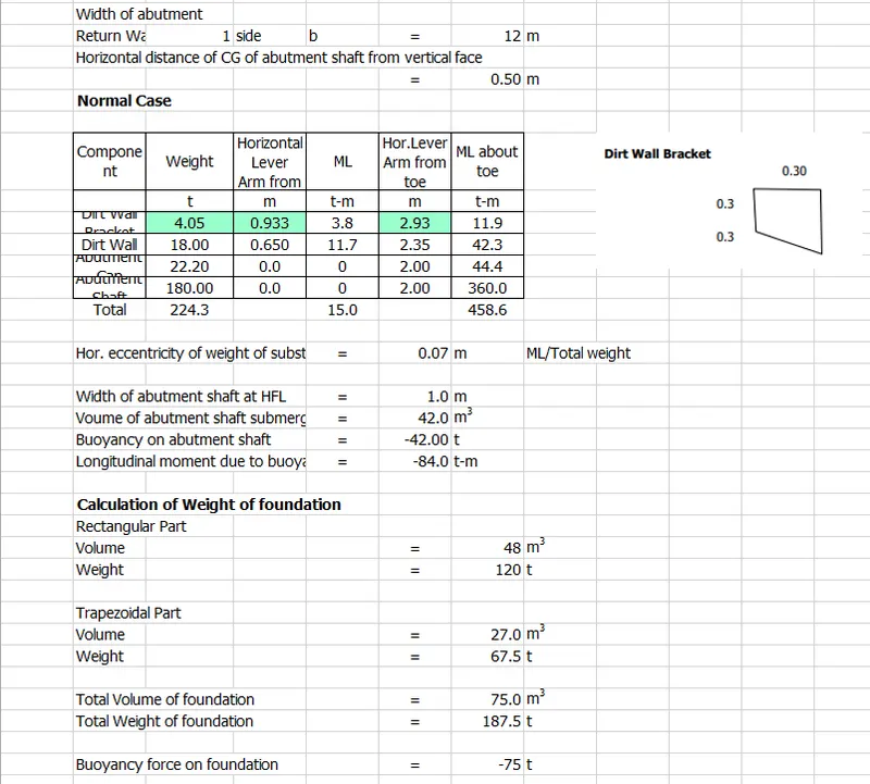
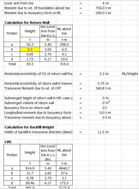
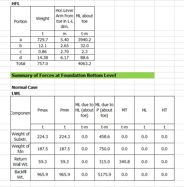
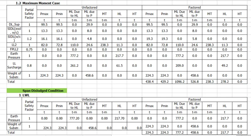
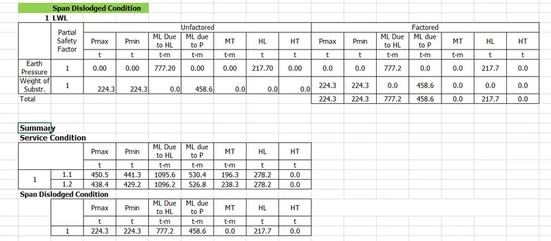
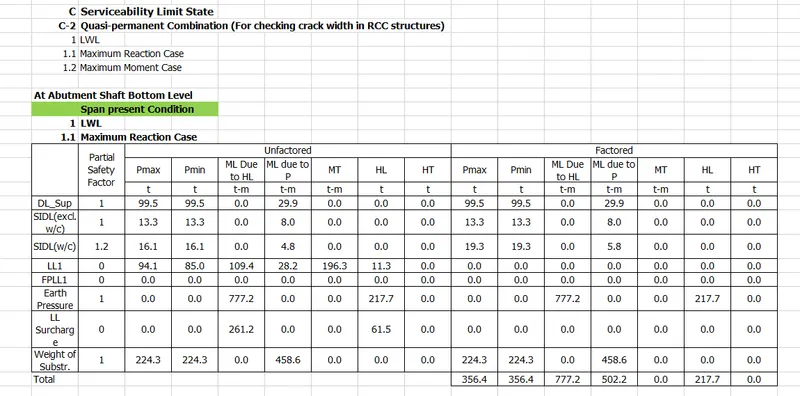
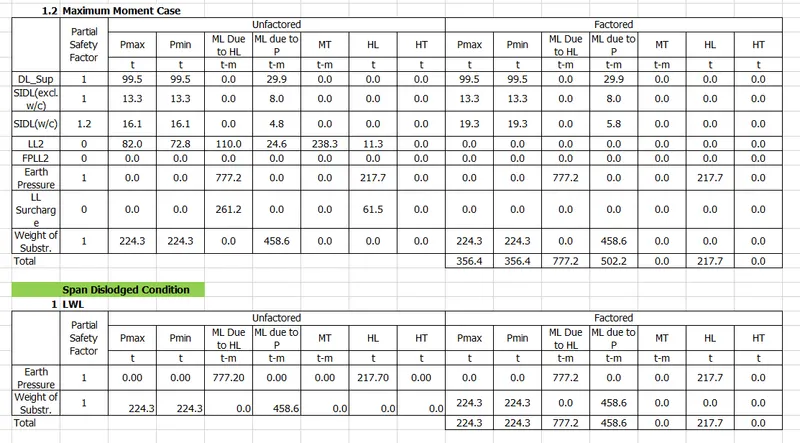
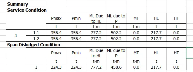
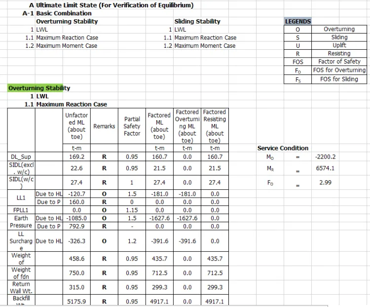
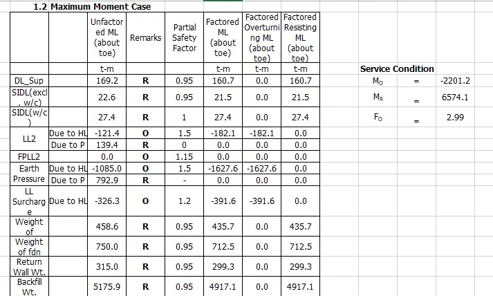
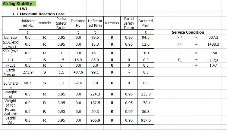
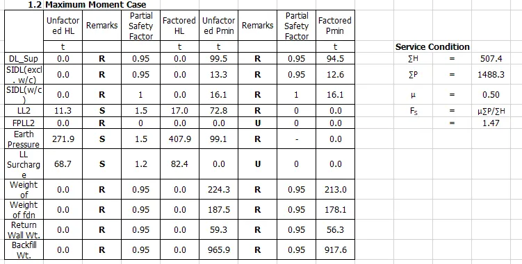
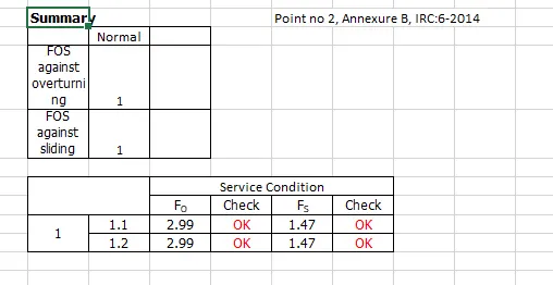
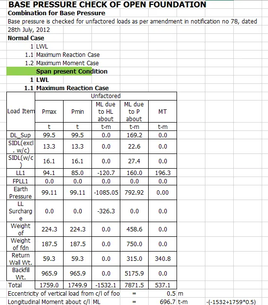
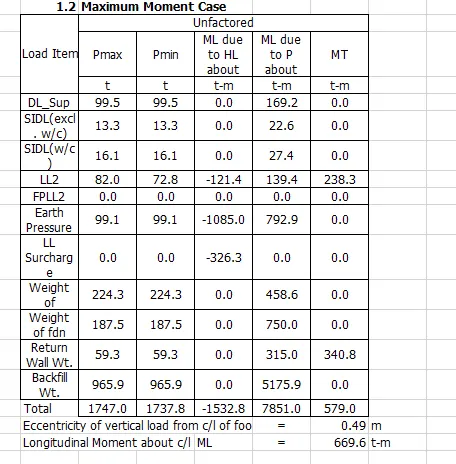
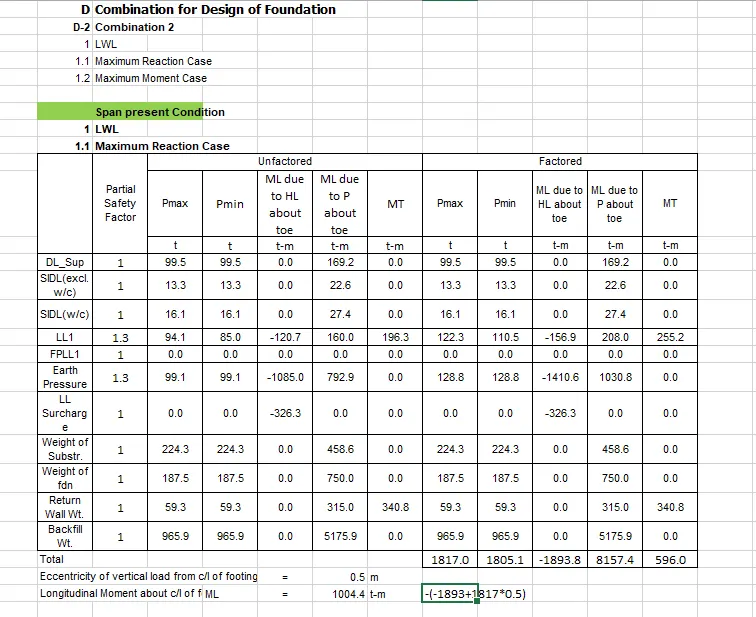
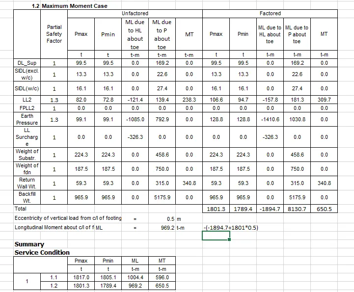
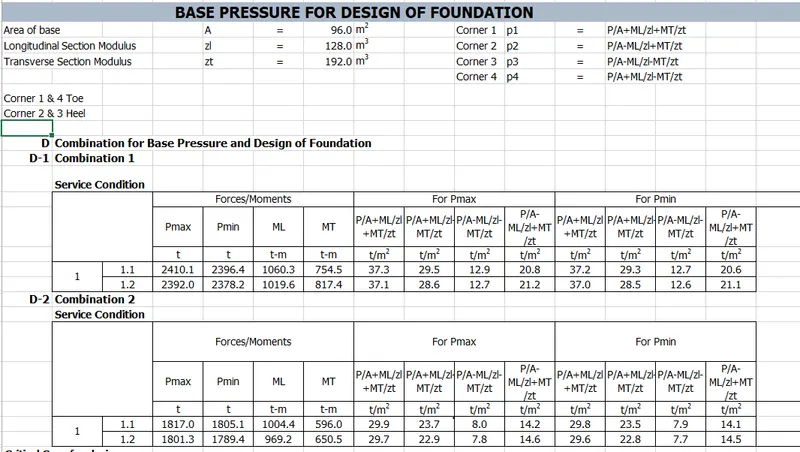
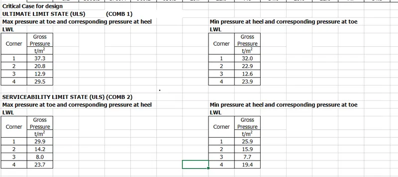
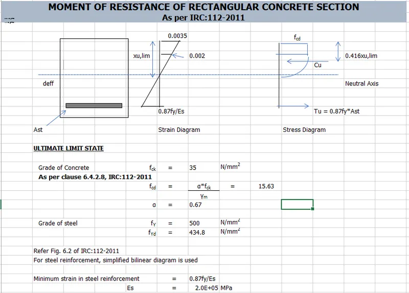
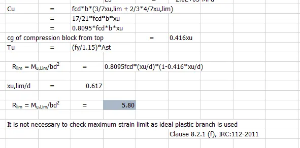
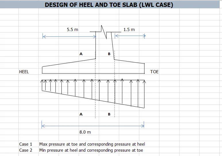
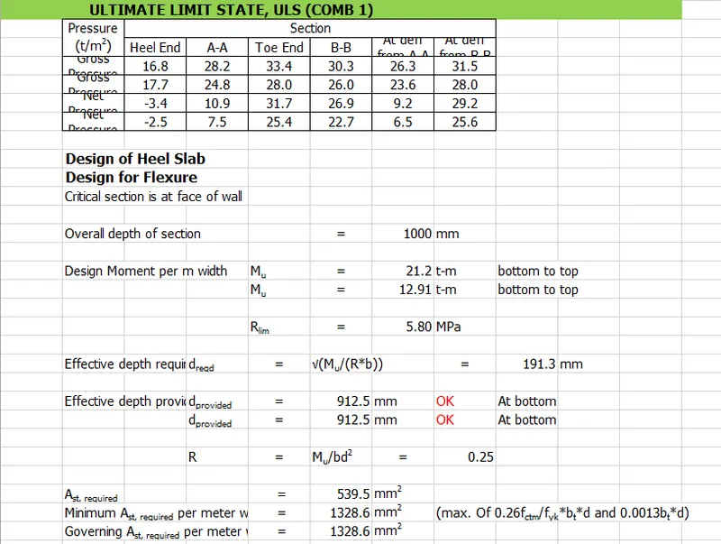
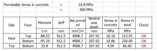
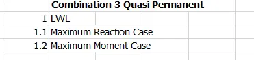
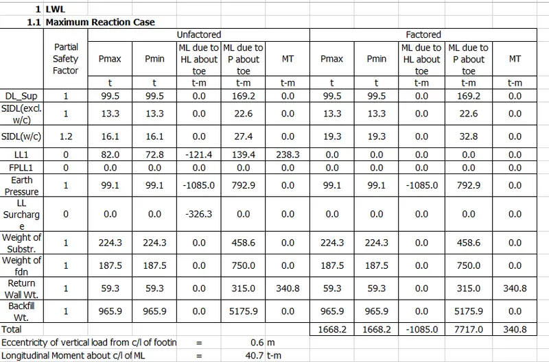
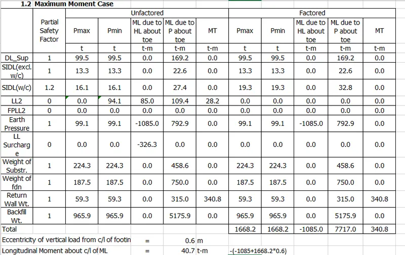
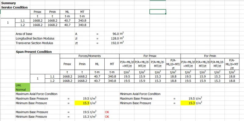
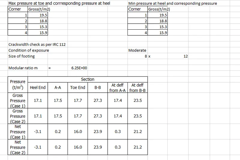
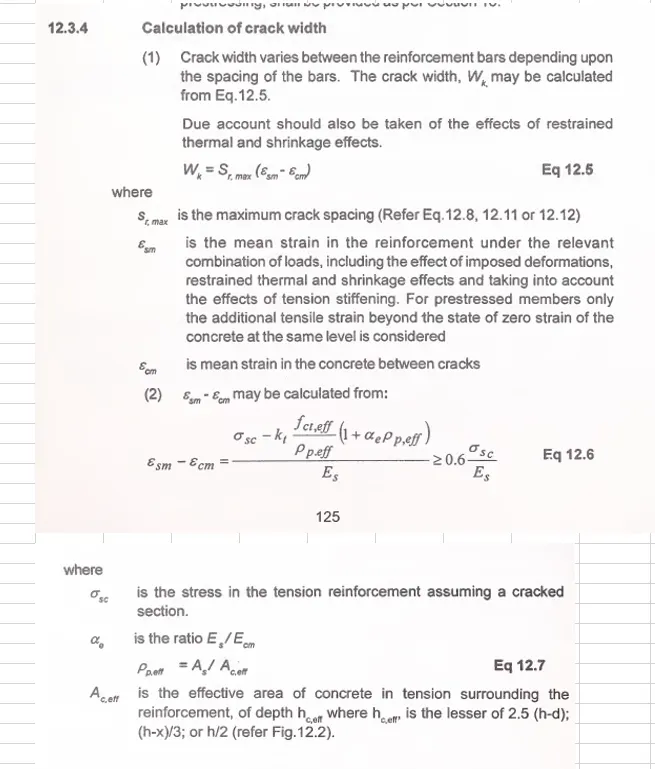
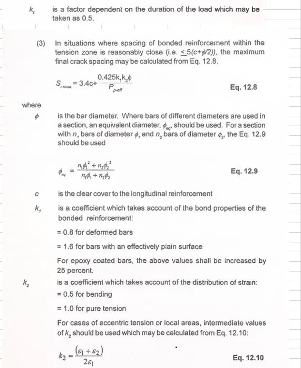
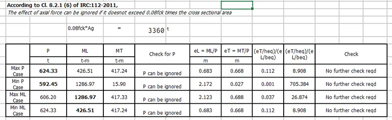
2. Check overturning and sliding of 4 m height of Abutment (from ground level) , embedded 2 m in ground.
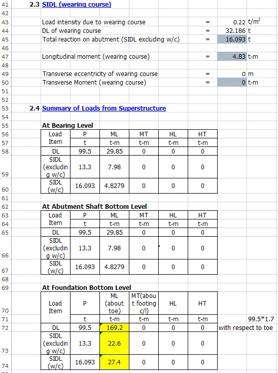
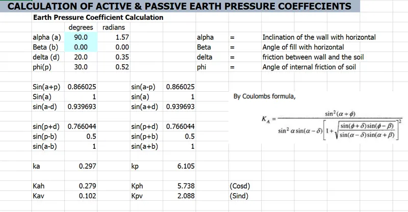
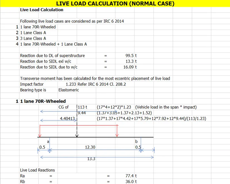
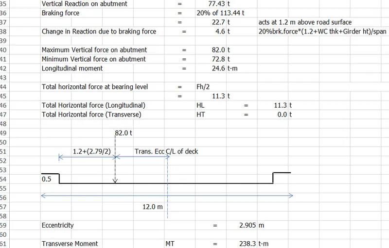
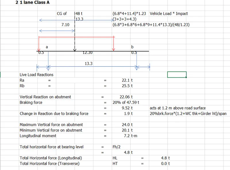
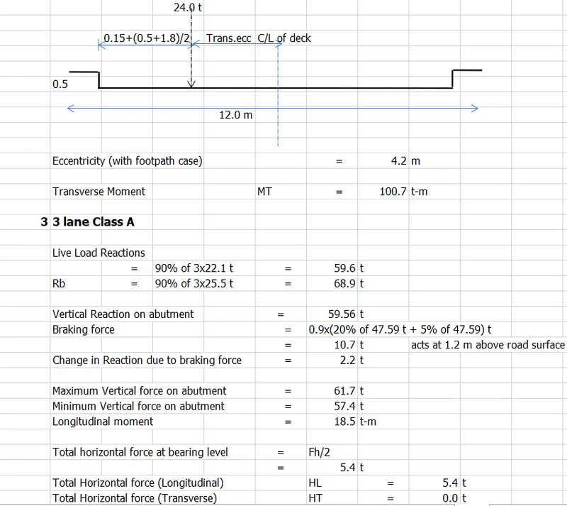
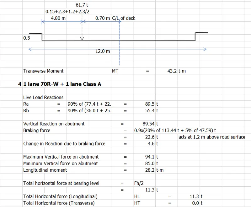
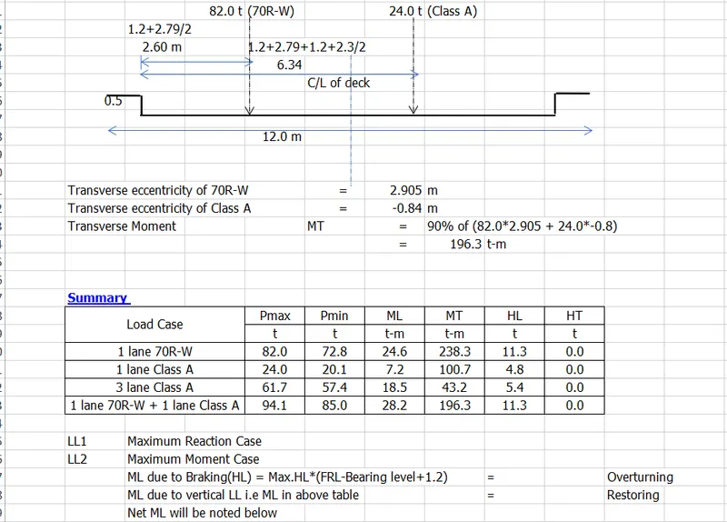
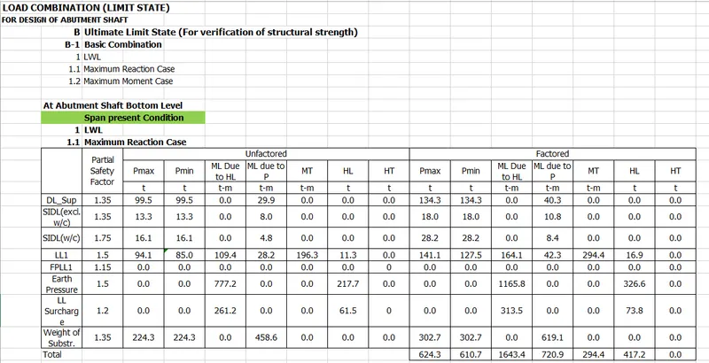
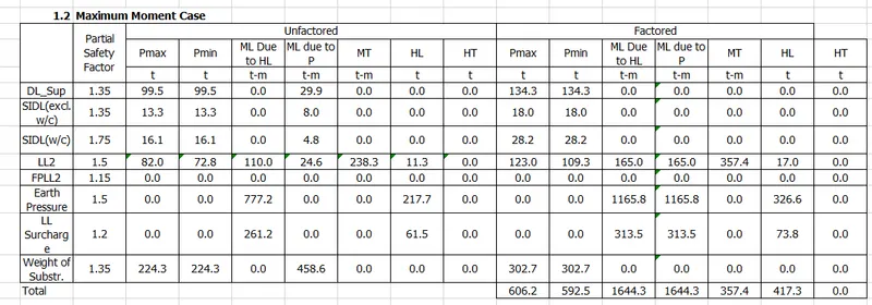
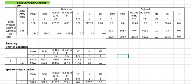
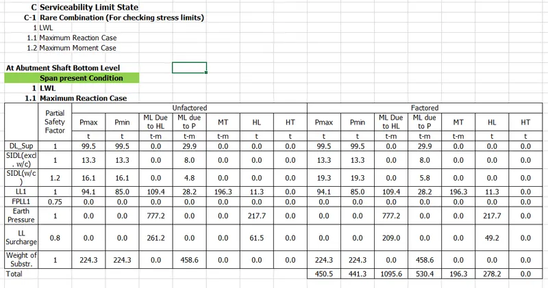

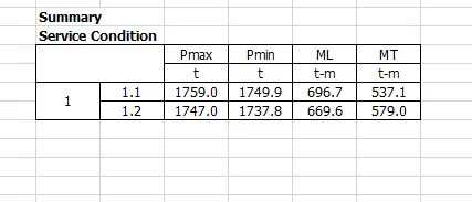
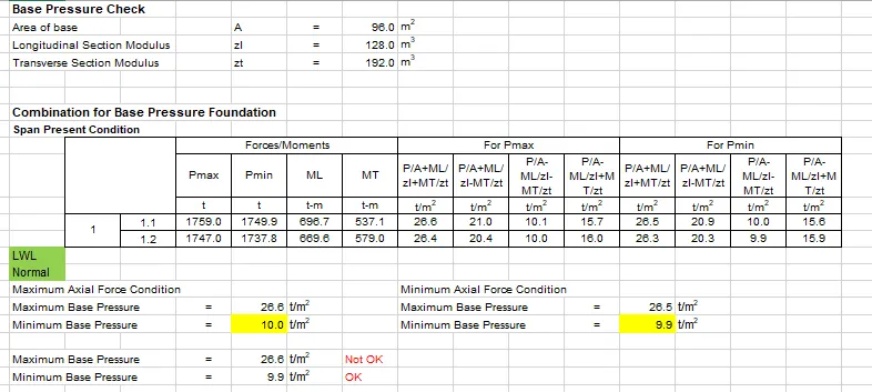
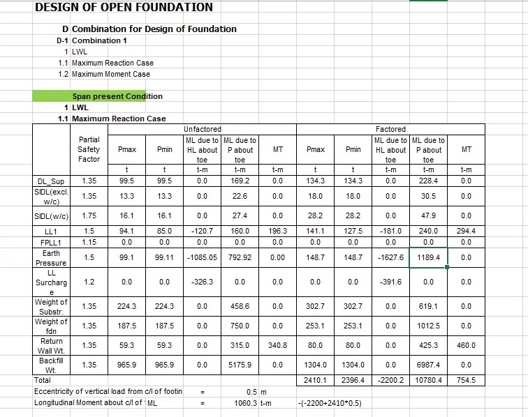
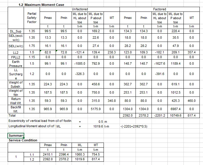
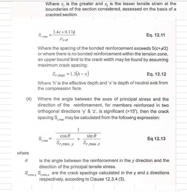
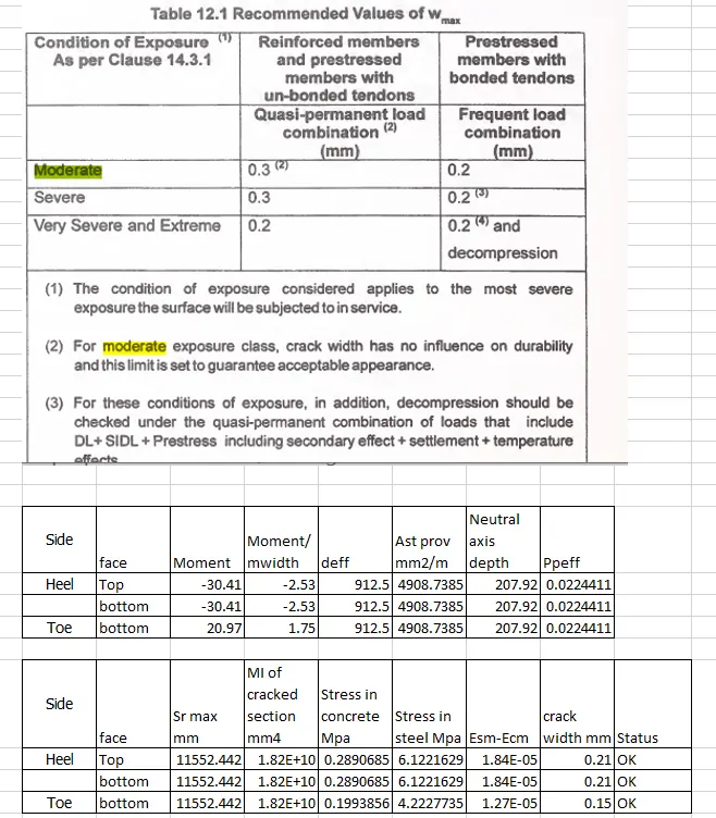
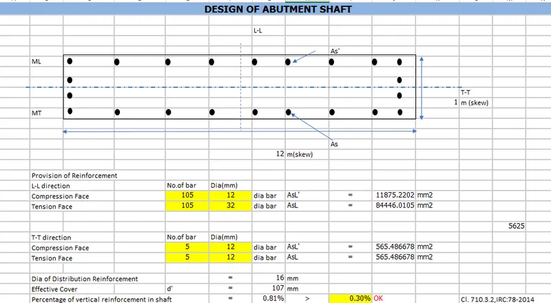
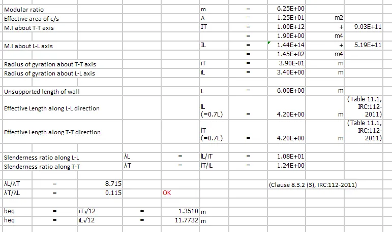
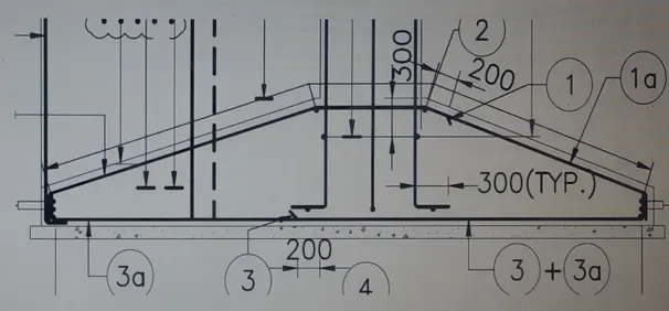
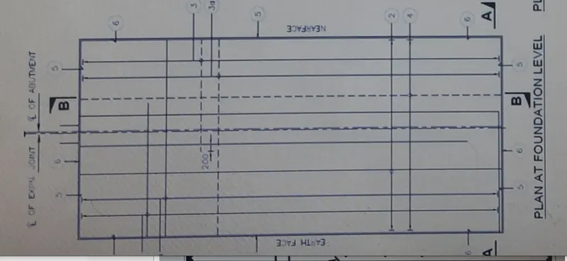
Detailing
2.How to decide the boreholes location and its depth of exploration in case of shallow foundation? What all the parameters we need to get from the site/geotechnical investigation for design of the foundation.
- The location of boreholes should be determined carefully and positioned properly to have test results that adequately represent the nature of the soil at project site. If the layout of the structure has not been established when site investigation is conducted, then it is recommended to consider uniformly spaced gird boreholes. Otherwise, boreholes should be positioned close to the suggested foundation especially in the case where the depth of bearing stratum is varied. Frequently, the spaces between borings are filled with static or dynamic probing as can be observed in Figure 1. If trial pits are used, they should be positioned away from the foundation location because it would weaken and disturb the ground. As per Eurocode 7 specifications, the spacing of exploration stations creating a grid ranges from 20 to 40m. The geological condition of the project site should be considered while spacing is specified for boreholes. If the geological formation varies substantially, then it is required to adopt small spacing and vice versa.
- The depth of boreholes is controlled by the depth of the soil that is under the influence of bearing pressure of the foundation. The recommended borehole depth is equal to one to three times the width of the loaded area. This is because it is suggested that bearing pressure below this depth would cause detrimental effect on the structure. If the shallow strip foundation is considered with considerable spacing, then deep boreholes would not be required as shown in Figure
.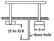
However, it will be required to dig deep boreholes in the case of large raft foundations as shown in Figure except in the case of encountering rock within the specified depth.
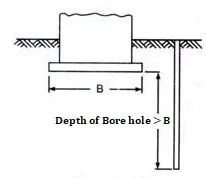
If strip or pad foundation effects are overlapping, then their behavior would be similar to that of raft foundation and eventually deep boreholes are needed to be sunk as shown in Figure.
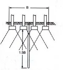
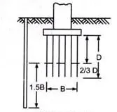
Parameters we need to get from the site/geotechnical investigation for design of the foundation are as follows,
Geological conditions of the site.
Drainage facilities at the site
Details of boring
Description of subsoil conditions as determined from the soil and rock samples collected
Ground water table level as observed from the boreholes
Details of foundation recommendations and alternatives
Bearing capacity of soil
Any anticipated construction problems
List different type of soils/rock (minimum 5)
Sandy Soil

Clayey Soil
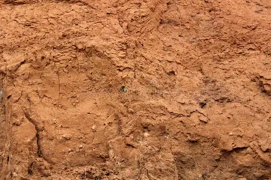
Gravel soil
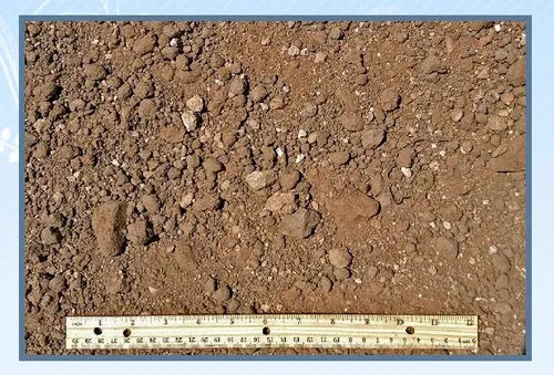
Silt SOil
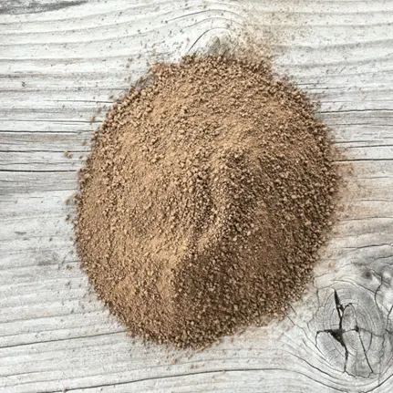
Criteria for the shallow foundations for selecting the foundation level,
- Bearing capacity should be high at ground level;
- Depth of foundation is less than the footing width;
- Underlying weaker strata do not result in undue settlement.
Typical Borehole log