Week 2:- BiW Fixture Basics Challenge
1. Project Execution Activity involves the following processes in any industry:-
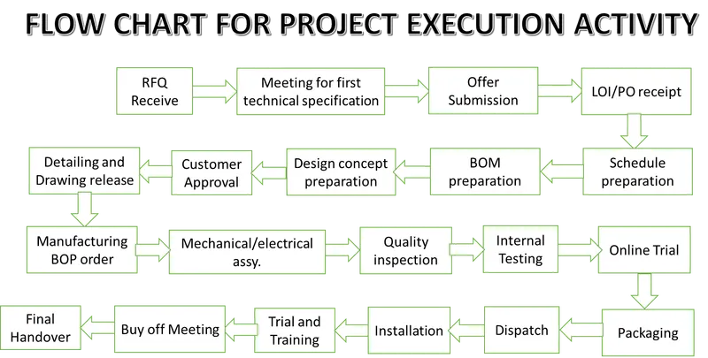
In the above image we can see how the project execution takes place in any industry:
- RFQ receive is the initial stage of project execution where a quotation for the required component is received from a customer by the concerned department of the organization. RFQ stands for "Request FOR Quote"
- Meeting for First Technical Specification: After receiving the RFQ the Technical team schedules an initial meeting with the Technical head and gathers all the technical data and study them carefully before approaching for design and production.
- Offer Submission: Once the meeting is done a technical offer for the required part is submitted in the documentation that has all the details of the technical details like weldings spots, type of welding, material grade, etc. And is shared with the customer for clarification.
- LOI/PO receipt: Once the clarification is done from the customer end, they send a purchase offer(PO) to the company for design preparation and production.
- Schedule Preparation: Once the company receives PO, the technical team and production team schedules preparation for development like Cycle time, Production plan study, etc.
- BOM Preparation: Bill Of Material required is prepared in an excel worksheet that defines all the parts that need to be procured outside and that need to be manufactured inhouse
- Design concept preparation: Design Team develops a conceptual design using 3D models and simulation is done in software which helps them create a design report of the component to be developed and that Design report is sent to the customer for approval.
- Customer approval: A Design report which is sent to customers for approval is received with their sealed stamp and signature so that Fabrication of components can be taken place.
- Detailing and Drawing release: After receiving the customer's approval document with stamp, the 2D Detailing team starts preparing Shop drawings, assembly drawings, and fabrication drawings which are then released to the Production department for schedule.
- Manufacturing BOP order: The parts which need to be procured from the outside like bearings, Fasteners, Motors, etc. all Bill of parts(BOP) are prepared by the 2D team and Design team to finish production on time.
- Mechanical/Electrical Assembly: Manufacturing of parts is done on the Production line and now all mechanical and electrical parts are needed to be assembled on the Assembly line.
- Quality inspection: While manufacturing and assembly a Quality inspector is always present online who inspects and checks all the coordinates and geometry of the component to make sure that while trial it works flawlessly.
- Internal Testing: After the part is developed in the production line with proper quality inspection, internal testing of the part is done apart from simulation on software. It is done just to make sure that the component has a long life and should be on run successfully.
- Online Trial: Customer/Clients demands for online/virtual test run of component or assembly to make sure all markings and coordinates are as per the offer submitted. Then he approves the product for packaging.
- Packaging: The Manufacturer is solely responsible for all damage and dispatch, keeping in mind the packaging of the product is done so that all risks of damage are avoided.
- Dispatch: Logistics department makes sure that the products that are to be sent to customers are safe while loading and unloading
- Installation: An installation manual or installation team is sent by the manufacturer for customer ease so that there is no difficulty for him to use the product while installation.
- Trials and Training: The installation team is trained such that they give trials for a week or two weeks such that the customer does not find any difficulty while showcasing it to the end-user or while using it for himself/herself.
- Buy-off Meeting: After trials and training work is done a buy-off meeting is set with the customer to establish a good business with the vendor.
- Final Handover the final is step is to hand over all related documents with the product to the customer.
2. JOINING PROCESSES:
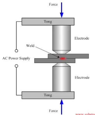
- Resistance Welding: In this type of joining process two metal workpieces are joined together by applying force to a consumable electrode through which AC or DC current is passing through to create a permanent joint between them. This force should be in moderate because if a high force is applied the sheets might weld due to over-heating and if lesser force is applied workpieces might not be joined and a spot mark is created which leads to a reduction in the life of the product. Some common examples of resistance welding are RSW- Resistance Spot Welding, RSMW- Resistance Seam Welding, RPW- Resistance Projection Welding
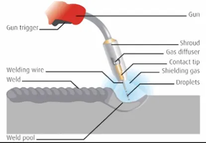
- Fusion Welding: In this type of welding a permanent joint is created between two workpieces that are to be fused together or welded together. Fusion of the workpieces can be done through either consumable or non-consumable electrodes through which high current flows and an electrical flux between the workpieces is created causing the workpiece to melt and get joined together. Some common examples of Fusion welding are MAW- Manual Arc Welding, SMAW- Submerged Arc Welding, TIG- Tungsten Inert Gas Welding, MIG- Metal Inert Gas Welding.
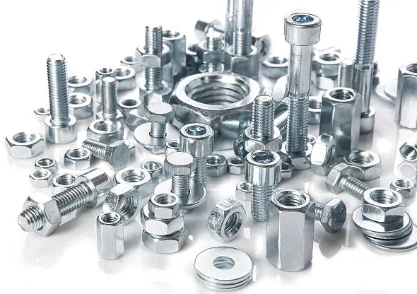
- Fastening: It is another type of joining process for BIW fixtures. In this, a hole is created in the parts of the fixture that are to be joined together, and then they are Fastened together using Nuts, Bolts, Washers Screws, etc.
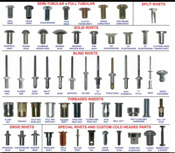
- Rivetting: In this type of joining process no holes are required for joining two members as the joining member is in form of a semi-circular rod which is inserted at the point using an automated gun and it creates a hole on members automatically and gets self-locked after insertion.
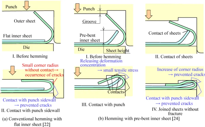
- Hemming: In this type of Joining process the edge of the part is rolled to itself to form the desired shape.
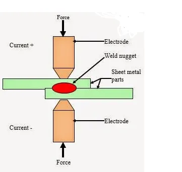
3. Resistance Welding: In this type of joining process two metal workpieces are joined together by applying force to a consumable electrode through which AC or DC current is passing through to create a permanent joint between them. This force should be in moderate because if a high force is applied the sheets might weld due to over-heating and if lesser force is applied workpieces might not be joined and a spot mark is created which leads to a reduction in the life of the product.
- RSW (Resistance Spot Welding): It is the type of resistance welding where two workpieces are joined using a consumable electrode passing through AC/DC voltage and a spot is created at the edges of the part to be joined that leads to a permanent joint between them by application of applied force by the user. eg: Doors, Window panes, etc.
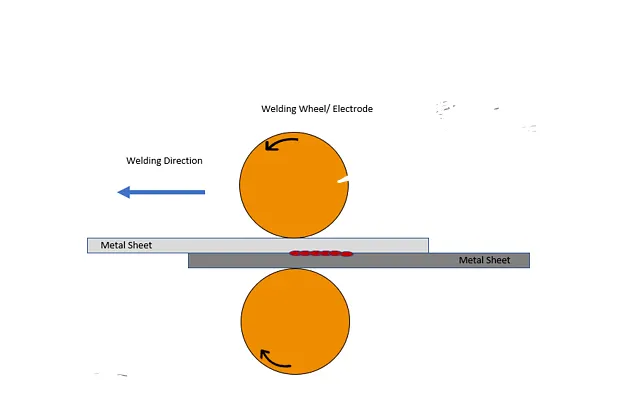
- RSW (Resistance Seam Welding): It is the type of resistance welding where hot-rolled electrodes are used and they both run in opposite directions on that side of the workpieces where they are free. Then some moment is applied at the electrodes and the workpieces' edges get welded in a seam. eg: fuel tanks, radiators, etc.
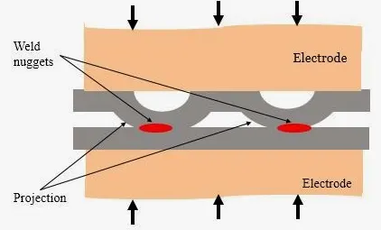
- RPW (Resistance Projection Welding): It is the type of resistance welding where two workpieces are joined using a consumable electrode passing through AC/DC voltage and a projection is created at the welded joint which is of the same projection as that of the part to be joined that leads to a permanent joint between them by application of applied force by the user. eg: welded nuts to a panel in the automotive industry.
4. Fusion welding: In this type of welding a permanent joint is created between two workpieces that are to be fused together or welded together. Fusion of the workpieces can be done through either consumable or non-consumable electrodes through which high current flows and an electrical flux between the workpieces is created causing the workpiece to melt and get joined together.
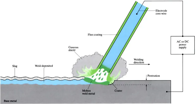
- Manual Arc Welding (MAW): It is the type of fusion welding process where a permanent joint is created between metal parts when an electric current flows through a consumable flux coated electrode that forms an electric arc due to electric flux and causes the metal to melt and join at the same time. eg: BIW components, chassis parts, etc.
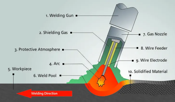
- Gas Metal Arc Welding or Metal Inert Gas Welding (GMAW or MIG): It is the most common type of fusion welding used in the automotive industry. It uses consumable wire electrodes that get melted in presence of inert gases like Argon(Ar) or Helium(He) when AC or DC is supplied to the system. eg: repairing cars, etc.
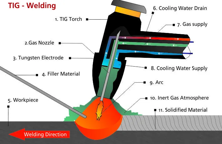
- Gas Tungsten Arc Welding or Tungsten Inert Gas Welding (GTAW or TIG): It is the most common type of fusion welding used in the automotive industry. It uses non-consumable tungsten electrodes to melt the metal parts thus releasing inert gases like Argon(Ar) or Helium(He) when AC or DC is supplied to the system. It works under very high temperatures compared to other welding processes. eg: Aluminum components of cars, etc.
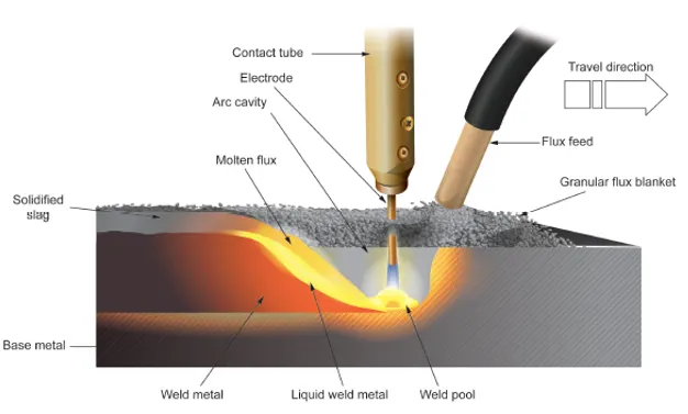
- Submerged Arc Welding: In this type of welding operation the metal parts that are to be welded are covered with flux material that has high weldability. And an electric current supply AC or DC to a consumable electrode is given such that an electric arc is formed between electrode and flux material such that they could join the parts. eg: Thick sheet applications in automotive industry
5. 3-2-1 PRINCIPLE:- It is the most common and efficient principle that is used for constraining a part in BIW fixtures. It involves the following steps to be performed while constraining a component in the BIW fixture:
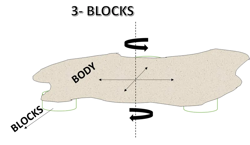
- 3- Blocks are placed on the ground such that their surface at the top is planar so that the component could be kept over it. Once the component is placed it can only move in that plane only and rotate about only one axis. Thus here we have constrained 2 Translations out of 6 and 4 rotations out of 6.
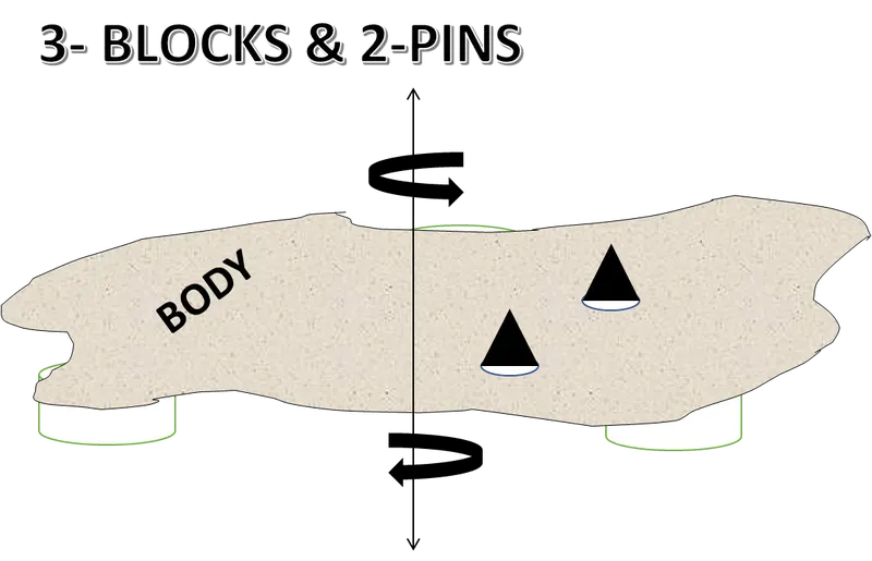
- 2- Now we know that the placed component can move in translation along 4 sides in two axes and rotate about only one axis which is perpendicular to the translation axes. So to constrain this rotation we place two pins on two holes of a component such that there is only one rotation and one translation is there for the component.
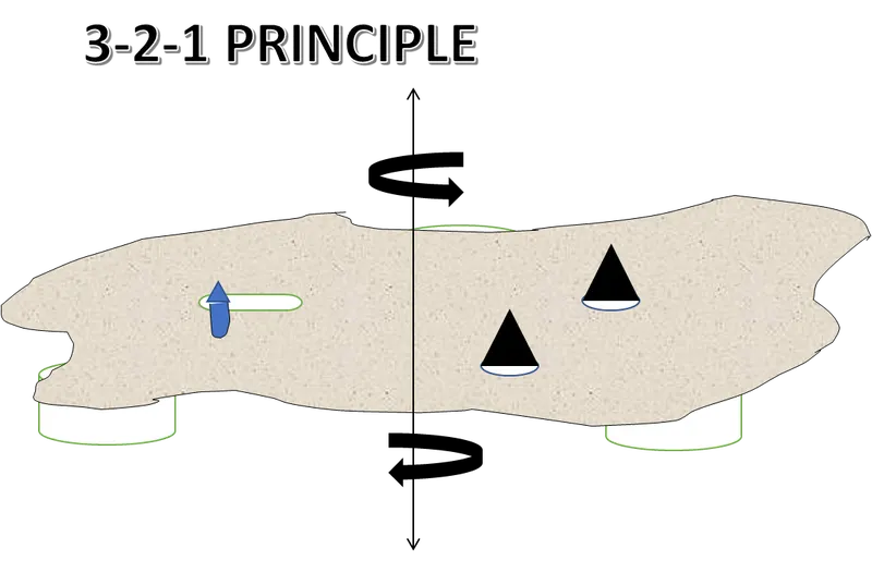
- 1- As after completion need only to pick up the component out of the fixture, so to do this we create a slot in the component such that rotation of component is constrained and there is only one translation at the end. And through that slot, a pin is inserted.
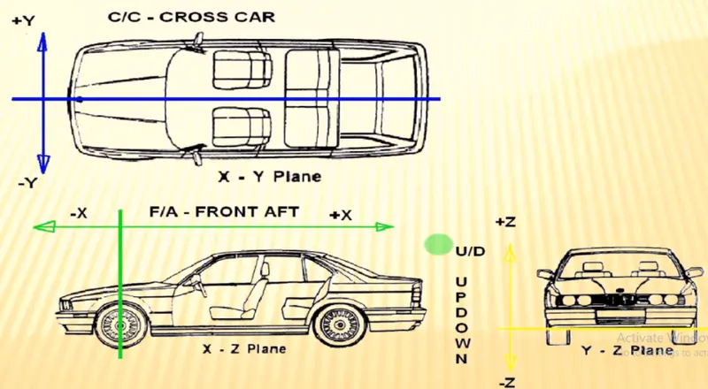
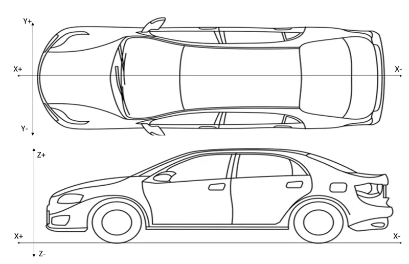
6. Body coordinate system: It defines the axis system of a car body for placement of BIW fixture design. It is measured using a Coordinate Measuring Machine (CMM). It is very useful in defining the points and placement of parts or components of a body. This defines the 12 DOFs of a car body. It is given as follows:
- X-X: This is the X-axis or Longitudinal axis of a Car body along the length of the car. This is also known as front O Line (FOL).
- Y-Y: This is the Y-axis or Transverse axis of a car body which is along the width of the car. This is also known as Center O Line (COL).
- Z-Z: This is the Z-axis or Vertical axis of a car body which is along with the height of a car. This is also known as Body O Line (BOL).
7. BODY PLANES: Similar to the Body Coordinate System(BCS), every car has its own Body Planes along which the dimensions and geometry of a car is defined. The measurements along the Body planes are called as Body-Line dimensions.
Following are the body planes of a car defined:-
- Front After (F/A): Distance along Front O Line
- Cross Car (C/C): Distance along Center O Line.
- Up Down (U/D): Distance along Body O Line.
These are the reference planes of a car that helps in defining the datum points and datum planes for Geometric Dimensioning and Tolerances i.e. GD & T.