Week 2:- BiW Fixture Basics Challenge
1.PROJECT EXECUTION ACTIVITY
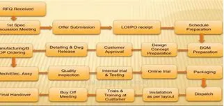
Project activities are those basically are being processed or being practiced in general project of BIW begins. Project activities are task from start to end of project. There are various step involved in project. Below fig. show flow chart of project activities
2. Types of joining processes
There are various processes to join two panels like folding/tab joint , Welding, self piercing rivet, pulling rivet, Self clinching, screw joints, bolting etc. Here are some of the processes which are used in BIW panel joining:
1. Spot Welding
Spot welding is a thermal process in which metals are joined by heat generated by resistance of electric current. In this work pieces(panels)are placed together under high pressure exerted by electrodes. When a large amount of current is passed through the panels , current melts the panelon that specific spot where electrodes are touching the panel and forms weld.
There are various guns to do spot welding but most commonly used guns are X – TYPE and C – TYPE gun. X guns are also known as scissors or pinch gun. These guns are selected on the basis of location of gun mount,tooling access and the geometry of the panel. X-Gun or C-Guns can different shapes of die post as per the requirement.
Mentioned area is known as die post of the gun.
X GUN :
In this gun actuator is parallel to the weld plane and and actuates about a pivot.
X type guns are used where accessibility is constraint.
C GUN :
C-type or straight action gun actuates perpendicular to the plane and in line with the weld.
GUN STROKES :
Working Condition: That condition when both electrodes on gun are touching the panel while doing spot welding is called as Working Condition.
Semi opening condition or intermediate stroke: After completing one stroke, gun moves to next spot without opening completely is knownas intermediate stroke or semi opening. This opening may differ as per the requirement.
Full Stroke or Full opening : it is the maximum open condition of moving electrodes of the gun.
Basics while considering a gun :
Preferably Fixed electrode should be visible to the operator.
Gun should have good reach-ability to all spots.
As much as possible same gun should be used for maximum no. of spots.
Tip wear out condition (preferably 5 mm) should be considered while designing the tool.
Self piercing Rivet(SPR) :
SPR- Self-piercing riveting is a cold mechanical fastening technique for joining of two or sheet metals or panels. For joining , the rivet is driven into the matel at a controlled force, piercing the panels, Then rivet radially expands into the bottom layer,due ti the shape of die, forming a mechanical interlock.
This process is quite helpful in joining of aluminium panels.
MIG WELDING(Metal Inert Gas) :
Metal inert gas welding or MIG Welding is based on the electric arc welding process where completion of an electric circuit between positive and negative poles creates an electric arc , which generates tremendous heat permitting the fusion welding of metals.
GLUE GUN :
Glue guns are used for metering of sealentso or adhesive bonds.
adhesive bonding and sealing are used for various applications in the modern automotive induastry.
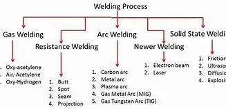
Today we will discuss about welding and types of welding. Welding is a process of joining similar and dissimilar metals or other material by application of heat with or without application of pressure and addition of filler material. It is used as permanent fasteners. Welding is essential process of every manufacturing industries. In fact, the future of any new metal may depend on how far it would lend itself to fabrication by welding. The weldability has been defined as the capacity of being welded into inseparable joints having specified properties such as definite weld strength proper structure. The weldability of any metal depends on five major factors. These are melting point, thermal conductivity, thermal expansion, surface condition, and change in microstructure.
Types of welding:
Basically welding may be classified into three types.
1. Plastic welding:
In plastic welding or pressure welding process, the pieces of metal to be joined are heated to a plastic state and then forced together by external pressure. These welding are also known as liquid-solid welding process. This procedure is used in forge welding and resistance welding.
2. Fusion welding:
In the fusion welding or no pressure welding process, the material at the joint is heated to a molten state and allowed to solidify. These welding are also known as liquid state welding process. This includes gas welding, arc welding, thermite welding etc.
3. Cold welding:
In this welding process, the joints are produced without application of heat, but by applying pressure which results diffusion or inter-surface molecular fusion of the parts to be joined. It is also known as solid state welding process. This process is mainly used for welding nonferrous sheet metal, particularly aluminum and its alloys. This includes ultrasonic welding, friction welding, Explosive welding etc.
4 Main Welding Processes:
1. Arc Welding (Fusion Welding):
In this type of welding process, weld metal melted from the edges to be joined and allow to solidifies from the liquid state and usually below the recrystallization temperature without any applied deformation. Arc welding is most extensively employed method of joining metal parts by fusion. In this welding the arc column is generated between an anode, which is the positive pole of power supply, and the cathode, the negative pole. When these two conductors of an electric circuit are brought together and separated for a small distance such that the current continues to flow through a path of ionized particles called plasma, an electric arc is formed. This ionized gas column acts as a high resistance conductor that enables more ions to flow from the anode to the cathode. Heat is generated as the ions strike the cathode. This heat used as melting of metal to be joined or melting the filler metal which further used as joining material of welding metal. The electrode is either consumable or non-consumable as per welding requirement. The temperature at the center of the arc being 6000 OC to 7000 OC
2. Gas Welding:
The gas welding is done by burning of combustible gas with air or oxygen in a concentrated flame of high temperature. As with other welding methods, the purpose of the flame is to heat and melt the parent metal and filler rod of a joint. It can weld most common materials
3. Gas Metal arc welding (MIG):
This welding is also known as metal inert gas welding. In this type of welding a metal rod is used as one electrode, while the work being welded is used as another electrode. It is a gas shielded metal arc welding which uses the high heat of an electric arc between a continuously fed, consumable electrode wire and the material to be welded. Metal is transferred through protected arc column to the work.
In this process the wire is fed continuously from a reel through a gun to constant surface imparts a current upon the wire. In this welding the welding area is flooded with a gas which will not combine with the metal. The rate of flow gas is sufficient to keep the oxygen of the air away from the hot metal surface while welding is being done.
4. Gas Tungsten Arc Welding (TIG):
This welding is also known as tungsten inert gas welding is similar to the MIG in that is uses the gases for shielding. This arc welding process uses the intense heat of an electric arc between a no consumable tungsten electrode and the material to be welded. In this process the electrode is not consumable during welding process and gas is used to protect the weld area form atmospheric air.
3.Resistance welding
Resistance welding can be defined as; it is a liquid state welding method where the metal-to-metal joint can be formed within a liquid state otherwise molten state. This is a thermoelectric method where heat can be generated at the It is a thermo-electric process in which heat is generated at the edge planes of welding plates because of electric resistance and a weld joint can be created by applying low-pressure to these plates. This type of welding uses electric resistance to generate heat. This process is very efficient with pollution free but the applications are limited because of the features like equipment cost is high, and material thickness is limited.
Resistance Welding
Resistance Welding Working Principle
The working principle of resistance welding is the generation of heat because of electric resistance. The resistance welding such as seam, spot, protection works on the same principle. Whenever the current flows through electric resistance, then heat will be generated. The same working principle can be used within the electric coil. The generated heat will depend on material’s resistance, applied current, conditions of a surface, applied the current time period
This heat generation takes place because of the energy conversion from electric to thermal. The resistance welding formula for heat generation is
H = I2RT
Where
‘H’ is a generated Heat, and the unit of heat is a joule
‘I’ is an electric current, and the unit of this is ampere
‘R’ is an electric resistance, and the unit of this is Ohm
‘T’ is the time of current flow, and the unit of this is second
The generated heat can be used to soften the edge metal to shape a tough weld joint with fusion. This method generates weld with no application of any flux, filler material, and shielding gases.
Types of Resistance Welding
Different types of resistance welding are discussed below.
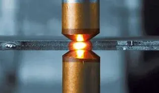
Spot Welding
Spot welding is the simplest type of welding where the work portions are held jointly below the force of anvil face. The copper (Cu) electrodes will make contact with the work portion & the flow of current through it. The work portion material applies a few resistances within current flow which will cause limited heat production. The resistance is high at the edge surfaces because of the air gap. The current begins to supply through it, then it will reduce the edge surface.
Spot Welding
The current supply & the time must be enough for the correct dissolving of edge faces. Now the flow of current will be stopped however the force applied with electrode continued for a second, whereas the weld quickly cooled. Later, the electrodes eliminate as well as get in touch with new spot to create a circular piece. The piece size mainly depends on electrode size (4-7 mm).
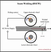
Seam Welding
This type of welding is also known as continuous spot welding where a roller form electrode can be utilized to supply current throughout work parts. Initially, the roller electrodes are getting in touch with the work part. High current can be supplied through these electrode rollers to melt the edge surfaces & shape a weld joint.
Seam Welding
At present, the electrode rollers will begin rolling on work plates to make a permanent weld joint. The weld timing & electrode movement can be controlled to guarantee that the weld overlap & work part doesn’t acquire too warm. The speed of the welding can be about 60 in per min within seam welding, which is used to make airtight joining
Resistance welding can be defined as; it is a liquid state welding method where the metal-to-metal joint can be formed within a liquid state otherwise molten state. This is a thermoelectric method where heat can be generated at the It is a thermo-electric process in which heat is generated at the edge planes of welding plates because of electric resistance and a weld joint can be created by applying low-pressure to these plates. This type of welding uses electric resistance to generate heat. This process is very efficient with pollution free but the applications are limited because of the features like equipment cost is high, and material thickness is limited.
Resistance Welding
Resistance Welding Working Principle
The working principle of resistance welding is the generation of heat because of electric resistance. The resistance welding such as seam, spot, protection works on the same principle. Whenever the current flows through electric resistance, then heat will be generated. The same working principle can be used within the electric coil. The generated heat will depend on material’s resistance, applied current, conditions of a surface, applied the current time period
This heat generation takes place because of the energy conversion from electric to thermal. The resistance welding formula for heat generation is
H = I2RT
Where
‘H’ is a generated Heat, and the unit of heat is a joule
‘I’ is an electric current, and the unit of this is ampere
‘R’ is an electric resistance, and the unit of this is Ohm
‘T’ is the time of current flow, and the unit of this is second
The generated heat can be used to soften the edge metal to shape a tough weld joint with fusion. This method generates weld with no application of any flux, filler material, and shielding gases.
Types of Resistance Welding
Different types of resistance welding are discussed below.
Spot Welding
Spot welding is the simplest type of welding where the work portions are held jointly below the force of anvil face. The copper (Cu) electrodes will make contact with the work portion & the flow of current through it. The work portion material applies a few resistances within current flow which will cause limited heat production. The resistance is high at the edge surfaces because of the air gap. The current begins to supply through it, then it will reduce the edge surface.
Spot Welding
The current supply & the time must be enough for the correct dissolving of edge faces. Now the flow of current will be stopped however the force applied with electrode continued for a second, whereas the weld quickly cooled. Later, the electrodes eliminate as well as get in touch with new spot to create a circular piece. The piece size mainly depends on electrode size (4-7 mm).
Seam Welding
This type of welding is also known as continuous spot welding where a roller form electrode can be utilized to supply current throughout work parts. Initially, the roller electrodes are getting in touch with the work part. High current can be supplied through these electrode rollers to melt the edge surfaces & shape a weld joint.
Seam Welding
At present, the electrode rollers will begin rolling on work plates to make a permanent weld joint. The weld timing & electrode movement can be controlled to guarantee that the weld overlap & work part doesn’t acquire too warm. The speed of the welding can be about 60 in per min within seam welding, which is used to make airtight joining
Resistance welding can be defined as; it is a liquid state welding method where the metal-to-metal joint can be formed within a liquid state otherwise molten state. This is a thermoelectric method where heat can be generated at the It is a thermo-electric process in which heat is generated at the edge planes of welding plates because of electric resistance and a weld joint can be created by applying low-pressure to these plates. This type of welding uses electric resistance to generate heat. This process is very efficient with pollution free but the applications are limited because of the features like equipment cost is high, and material thickness is limited.
Resistance Welding
Resistance Welding Working Principle
The working principle of resistance welding is the generation of heat because of electric resistance. The resistance welding such as seam, spot, protection works on the same principle. Whenever the current flows through electric resistance, then heat will be generated. The same working principle can be used within the electric coil. The generated heat will depend on material’s resistance, applied current, conditions of a surface, applied the current time period
This heat generation takes place because of the energy conversion from electric to thermal. The resistance welding formula for heat generation is
H = I2RT
Where
‘H’ is a generated Heat, and the unit of heat is a joule
‘I’ is an electric current, and the unit of this is ampere
‘R’ is an electric resistance, and the unit of this is Ohm
‘T’ is the time of current flow, and the unit of this is second
The generated heat can be used to soften the edge metal to shape a tough weld joint with fusion. This method generates weld with no application of any flux, filler material, and shielding gases.
Types of Resistance Welding
Different types of resistance welding are discussed below.
Spot Welding
Spot welding is the simplest type of welding where the work portions are held jointly below the force of anvil face. The copper (Cu) electrodes will make contact with the work portion & the flow of current through it. The work portion material applies a few resistances within current flow which will cause limited heat production. The resistance is high at the edge surfaces because of the air gap. The current begins to supply through it, then it will reduce the edge surface.
Spot Welding
The current supply & the time must be enough for the correct dissolving of edge faces. Now the flow of current will be stopped however the force applied with electrode continued for a second, whereas the weld quickly cooled. Later, the electrodes eliminate as well as get in touch with new spot to create a circular piece. The piece size mainly depends on electrode size (4-7 mm).
Seam Welding
This type of welding is also known as continuous spot welding where a roller form electrode can be utilized to supply current throughout work parts. Initially, the roller electrodes are getting in touch with the work part. High current can be supplied through these electrode rollers to melt the edge surfaces & shape a weld joint.
Seam Welding
At present, the electrode rollers will begin rolling on work plates to make a permanent weld joint. The weld timing & electrode movement can be controlled to guarantee that the weld overlap & work part doesn’t acquire too warm. The speed of the welding can be about 60 in per min within seam welding, which is used to make airtight joining
Resistance welding can be defined as; it is a liquid state welding method where the metal-to-metal joint can be formed within a liquid state otherwise molten state. This is a thermoelectric method where heat can be generated at the It is a thermo-electric process in which heat is generated at the edge planes of welding plates because of electric resistance and a weld joint can be created by applying low-pressure to these plates. This type of welding uses electric resistance to generate heat. This process is very efficient with pollution free but the applications are limited because of the features like equipment cost is high, and material thickness is limited.
Resistance Welding
Resistance Welding Working Principle
The working principle of resistance welding is the generation of heat because of electric resistance. The resistance welding such as seam, spot, protection works on the same principle. Whenever the current flows through electric resistance, then heat will be generated. The same working principle can be used within the electric coil. The generated heat will depend on material’s resistance, applied current, conditions of a surface, applied the current time period
This heat generation takes place because of the energy conversion from electric to thermal. The resistance welding formula for heat generation is
H = I2RT
Where
‘H’ is a generated Heat, and the unit of heat is a joule
‘I’ is an electric current, and the unit of this is ampere
‘R’ is an electric resistance, and the unit of this is Ohm
‘T’ is the time of current flow, and the unit of this is second
The generated heat can be used to soften the edge metal to shape a tough weld joint with fusion. This method generates weld with no application of any flux, filler material, and shielding gases.
Types of Resistance Welding
Different types of resistance welding are discussed below.
Spot Welding
Spot welding is the simplest type of welding where the work portions are held jointly below the force of anvil face. The copper (Cu) electrodes will make contact with the work portion & the flow of current through it. The work portion material applies a few resistances within current flow which will cause limited heat production. The resistance is high at the edge surfaces because of the air gap. The current begins to supply through it, then it will reduce the edge surface.
Spot Welding
The current supply & the time must be enough for the correct dissolving of edge faces. Now the flow of current will be stopped however the force applied with electrode continued for a second, whereas the weld quickly cooled. Later, the electrodes eliminate as well as get in touch with new spot to create a circular piece. The piece size mainly depends on electrode size (4-7 mm).
Seam Welding
This type of welding is also known as continuous spot welding where a roller form electrode can be utilized to supply current throughout work parts. Initially, the roller electrodes are getting in touch with the work part. High current can be supplied through these electrode rollers to melt the edge surfaces & shape a weld joint.
Seam Welding
At present, the electrode rollers will begin rolling on work plates to make a permanent weld joint. The weld timing & electrode movement can be controlled to guarantee that the weld overlap & work part doesn’t acquire too warm. The speed of the welding can be about 60 in per min within seam welding, which is used to make airtight joining
4 FUSION WELDING
Welding can be defined as one of the manufacturing processes by which two or more similar or dissimilar materials can be joined permanently by coalescence formation with or without the applications of external pressure, heat or filler material. Fusion of faying surfaces of parent materials is not necessary for weld bead formation. On the basis of base material fuses or not, welding processes can be broadly classified into two groups—solid state welding and fusion welding. If faying surfaces of parent materials along with filler material melt down to form weld bead, it is termed as fusion welding. On the other hand, if no melting takes place during welding, then it is termed as solid state welding. However, in solid state welding, parent parts may be heated to an elevated temperature (but below its melting point).
What is fusion welding?
Fusion welding processes are all those welding processes where faying surfaces of parent part as well as filler material melt down during welding for weld bead formation. So heat is always associated with these processes. External application of pressure is not required for these processes, except for resistance welding group where substantial contact pressure needs to be maintained during welding for sound joining. Filler material may or may not be applied.
Examples of fusion welding processes
There exist a large number of fusion welding processes and the same can be further grouped on the basis of source of heat. Such processes where heat is applied by means of electric arc are termed as arc welding process. Similarly, all gas welding processes, resistant welding processes, and intense energy welding processes are basically examples of fusion welding. A list of such processes is provided below.
Arc welding processes
Shielded Metal Arc Welding (SMAW)
Gas Metal Arc Welding (GMAW)
Tungsten Inert Gas (TIG) welding
Submerged Arc Welding (SAW)
Flux Cored Arc Welding (FCAW)
Electro-Slag Welding (ESW)
Electro-Gas Welding (EGW)
Arc Stud Welding (SW)
Carbon Arc Welding (CAW)
Atomic Hydrogen Welding (AHW)
Gas welding processes
Air-Acetylene Welding (AAW)
Oxy-Acetylene Welding (OAW)
Oxy-Hydrogen Welding (OHW)
Pressure Gas Welding (PGW)
Resistance welding processes (many consider this as solid-state welding)
Resistance Spot Welding (RSW)
Resistance Seam Welding (RSEW)
Projection Welding (PW)
Percussion Welding (PEW)
Flash Welding (FW)
Upset Welding (UW)
Intense energy welding processes
Plasma Arc Welding (PAW)
Electron Beam Welding (EBW)
Laser Beam Welding (LBW)
Advantages of fusion welding processes
Filler material can be applied easily. So a large lacuna can be filled.
No need to apply external pressure, so primary shape of the components does not matter (a suitable shape is required to uniformly apply pressure).
Joint design and edge preparation are not crucial as these parameters affect only achievable penetration.
More than two components can easily be welded at a step.
Disadvantages of fusion welding processes
The process is associated with distortion and residual stress generation as it involves melting and solidification.
Palpable heat affected zone (HAZ) exists in the welded components. HAZ is always considered as the weak portion in welded assembly.
Mechanical properties of parent materials are also severely affected by intense heating.
Joining dissimilar metals by fusion welding is challenging task, especially if the metals have substantially different melting point and coefficient of thermal expansion.
5.321 principle
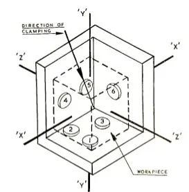
The 321 principle one of the methods how the parts degree of freedoms are arrested. In 321 principle, the primary (usually a plane) locks 3 degree of freedom, 2 rotations and 1 translation respectively.
3-2-1 Principle of Location. The 3-2-1 principle of location (six point location principle) is used to constrain the movement of workpiece along the three axes XX, YY, and ZZ. This is achieved by providing six locating points, 3 pins in base plate, 2 pins in vertical plane and 1 pin in a plane which is perpendicular to first two planes.
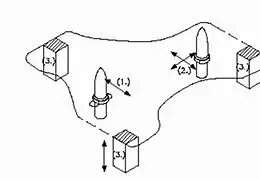
6 translational degrees of freedom**: +X, -X, +Y, -Y, +Z, -Z**
And 6 rotational degrees of freedom:
- Clockwise around X axis (CROT-X)
- Anticlockwise around X axis (ACROT-X)
- Clockwise around Y axis (CROT-Y)
- Anticlockwise around Y axis (ACROT-Y
- Clockwise around Z axis (CROT-Z)
- Anticlockwise around Z axis (ACROT-Z)
ou must fix all the 12 degrees of freedom except the three transitional degrees of freedom (-X, -Y and -Z) in order to locate the work piece in the fixture. So, 9 degrees of freedom of the work piece need to be fixed.
But, how? By using the 3-2-1 method as shoon below:
Rest the work piece on three non-collinear points of the bottom surface (XY), and you will be able to fix the +Z, CROT-X, ACROT-X, CROT-Y and ACROT-Y degrees of freedom**.**
Now, rest the work piece at two points of side surface (XZ), and you will be able to fix the +Y and ACROT-Z degrees of freedom.
Now, rest the work piece at one point of the adjacent surface (YZ), and you will be able to fix the +X and CROT-Z degrees of freedom.
So, you can successfully fixate 9 required degrees of freedom by using the 3-2-1 principle of fixture design.
Conclusion
The jig and fixture are tools used for holding the work piece in a correct location for mass production. Various types of fixtures (like drilling fixtures, milling fixtures, and welding fixtures) are used in industry. The 3-2-1 method is the fundamental principle for all types of fixture design.
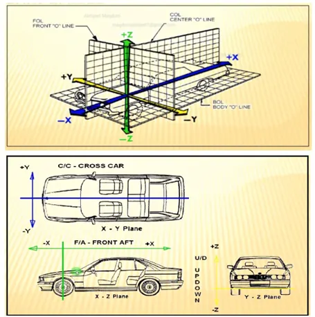
6.Body coordinate system
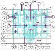
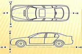
Body coordinate system in BIW The body coordinate system has been widely used in the automotive industry for drawing of body parts,Products and process design. A coordinate system is a reference system consisting of a set of points,lines and surfaces,used to define the positions of points in space in either two or three dimensions.
Body coordinate system in BIW The body coordinate system has been widely used in the automotive industry for drawing of body parts,Products and process design. A coordinate system is a reference system consisting of a set of points,lines and surfaces,used to define the positions of points in space in either two or three dimensions.
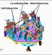
In short it shows in 2D XY, YZ or XZ coordinate position of BIW welding fixture parts or assemblies with reference to origin X=0,Y=0,Z=0 Let us consider a situation if individual fixture designer starts designing a part or panel on their default axes system then it will be difficult to assembly or position the part wi
6.Elaborate Body plane system
Elaborate Body plane system & its essentials. The body planes are used for defining the GD&T for the parts. These planes are perpendicular to each other. Use of body plane. used for define exact position of each part of the car. used for quality inspection ; used for making a standard system; used for assembly of the car; used for locating all the parts
There are four major types of body planes, and an easy way to remember them is to remember the acronym “SOFT,” which stands for Two of these planes are vertical (sagittal and frontal), running from top to bottom. One plane is horizontal (transverse), and the oblique planes are all the “odd” angles in between the horizontal and vertical angles.