Week 2:- BiW Fixture Basics Challenge
1. 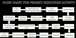
1)RFQ received - This id the first step in any project. RFQ stands for Request for Quotation. In this customer specifies his requirements, specifications etc. in form of documents or data. Also customer specifies its Technical offer, commercial offer, how the project will be executed & timeline to complete the project in it.
2) 1st spec discussion & offer submission - In this the documents created technical offer, commercial offer, project execution, Timeline required to complete the project are prepared. The time required to 3D design, Analysis of design, drawing & detailing, manufacturing, Assembly & commissioning etc. is considered. Then the cost of all the operation is also considered. By considering these kind of things the offer is prepared & submitted to the customer.
3) LOI/PO Receipt - The customer will study the offer submitted. He will also take quotations from others. The customer will study all the offers, compare offers & then select owner offer which suits best. The customer will generate means Purchase order to start the work.
4) Schedule preparation - After receiving the PO the project officially start. The timeline is fixed so there should be plan to beat the deadline & to complete the project. All the activities step by step are taken into account like receipt, 1st meeting, design date analysis, 3D design preparation & simulation etc. the time required to finish the individual activity is calculated. By calculating all the steps the total time required is calculated. It should beat the timeline & if not then modifications is done in schedule to beat the timeline of the project. We should have some back up plan for this Because due to some reasons our tasks not complete on the fixed date or the next task is dependent on previous task.
5)BOM preparation - Bill of material is prepared for the project like the BO parts, grippers, cylinders, motors etc. which are required.
6) Design concept preparation - The customer gives data or the specifications for the design. Based on that data design process is start which fulfills all the customer requirements.
7) Customer approval - After designing the concept the approval of the customer is required. Customer checks the design fulfills the requirements or not according to the technical offer. If yes the customer gives approval for the design or customer will also ask for some addition or the changes in the design. By doing the necessary changes final approval is taken from the customer.
8) Detailing & DWG release - After the approval from customer DWG are released which shows the detailed specifications of all the parts required. Like dimensions, Qty, Specifications etc.
9) Manufacturing BOP ordering - The BO parts like motors, cylinders, sensors, gripper etc. required for manufacturing are ordered as per the design specifications.
10) Mechanical/ Electrical assembly- Once the parts are received they goes for the prior Quality control checking. In this all the parts are checked as per the specification. After QC checking the Mechanical or electrical assemblies are prepared as per the design.
11)Quality inspection - After the assembly again the quality is checked. In this all the dimensions, positional accuracy, Coordinates are checked by using CMM machine.
12) Internal trial & testing & online trial - After the QC check internal trials are taken to check the fixture can do the operation or not for what it is designed. The simulation is done for this purpose at early stage. In this the fixture is checked for the clamping of the part, welding ,proper loading & unloading of the part etc.
After this online trial is taken in which all the operations done in automated mode by using electrical connections. The process sequence is checked as per the defined way in design in automated mode. Customer is also involved in online trial for taking the approval.
13) Packaging & dispatch - The assemblies are packed in proper manner. Because in transportation the fixture will be damaged hence it distorts the geometry of the fixture & also the functionality of the fixture. Hence the proper packaging is very important. Once the packaging is done the fixture is dispatched to the customer address.
14) Installation as per layout - layout is the space defined for the parts like fixture, robots etc., according to the functionality, application, process sequence etc. The layout is done at very initial level & according to that installation is done.
15) Trials & training at customer - Production trials are taken at customers end. In technical offer we have specified the quality benchmarks for the fixture, the capability of the fixture for production etc. The trials are taken to check the capability of the fixture. Once it is done then training is given to the operator, staff & engineer for the process sequence, how the fixture works, loading & unloading of the part etc.
16)Buy off meeting & Final handover - After production trial & training Customer check all the prescribed things in the offer are done or not. Sometime customer want some addition work also, so according to the requirement all the points are closed & after that project finally handed over to the customer.
2.
- Welded Joints
- Threaded joints
- Riveted joints
TYPES OF WELDING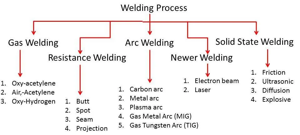
3. Resistance welding is a method of joining metals using heat generated by electrical resistance and pressure. This process creates strong, durable joints without the need for filler metal, making it efficient for large-scale production.
It's a cost-effective and efficient method, especially for joining steel and increasingly for aluminum and other alloys. Other applications include battery pack assembly, exhaust systems, and attaching fasteners to seating and interior components.Specific Applications:
- Body-in-White (BIW) Assembly
- Battery Pack Assembly (Electric Vehicles)
- Exhaust Systems
4. Fusion welding joins metals by melting them at high temperatures and allowing the molten metal to fuse together. Common types include gas welding, arc welding, resistance welding, and laser welding. In the automotive sector, fusion welding is used for various applications like body panel joining, chassis assembly, fuel tank fabrication, and battery assembly
Application of Fusion Welding:
(1) Friction welding is used for automobile valve stems, rear axles, half shafts, steering rods and vehicle tools
(2) Electron beam welding is used for gears, rear axles, etc. (3) Laser welding is used for cutting and trimming of body panels, gears, parts, etc.,
5. The 3-2-1 principle is a method of constraining the six degrees of freedom of a part. Six degrees of freedom means that a part can move in three linear directions (X, Y, and Z) and rotate in three rotational directions (pitch, roll, and yaw).Three Points (Primary Plane):
These points, located on the primary plane, restrict two rotational degrees of freedom and one translational degree of freedomTwo Points (Secondary Plane):
These points, perpendicular to the primary plane, restrict another translational degree of freedom and one rotational degree of freedomOne Point (Tertiary Plane):
This final point, perpendicular to both the primary and secondary planes, restricts the remaining translational degree of freedom.
6. Coordinate system is a reference system Consisting of a set of point, Lines & surfaces used to define position of point in space either in 2 or 3 dimensions. In general BCS is also called as car line or Body line- Car lines are the (Grid lines) shown on the fixture, which virtually represent the same location in the BIW. All the car line on fixture display the coordinate at corner for reference. With these lines one can easily relate the, location in BIW. Some times single coordinate hole is given in the fixture, that also represent the car line coordinates, from that reference point fixture is made and can be inspected. Body coordinate are mentioned near the hole
7. Body planes are three mutually perpendicular imaginary planes. These are reference planes in automotive car. These are used to define GD & T of all parts in automotive domain.- The measurement from body plane to parts are called body plane dimensions.
- It defines exact position of each product in the vehicle w.r.t a fixed origin.
- It ensures flawless design for assembly.
- While designing lines, all the designs are carried out relative to the bodylines viz. fixtures, Turntables etc.
- It assist in easy location of different parts in the vehicle.
- It aims in creating a standardized system.
- It assist in quality checks.
fig- shows general body plane system
- Bodylines dimensions are essential for below reason
- Some examples which shows how we use body plane to define the exact position of part is shown below.
fig-shows the use of x plane to define the length
fig-shows the use of z plane to define the height
fig-shows the use of y plane to define the width