Week 2:- BiW Fixture Basics Challenge
1. What is the process of project execution activity?
Ans : Deliver the actual work, outputs, and deliverables of a project.
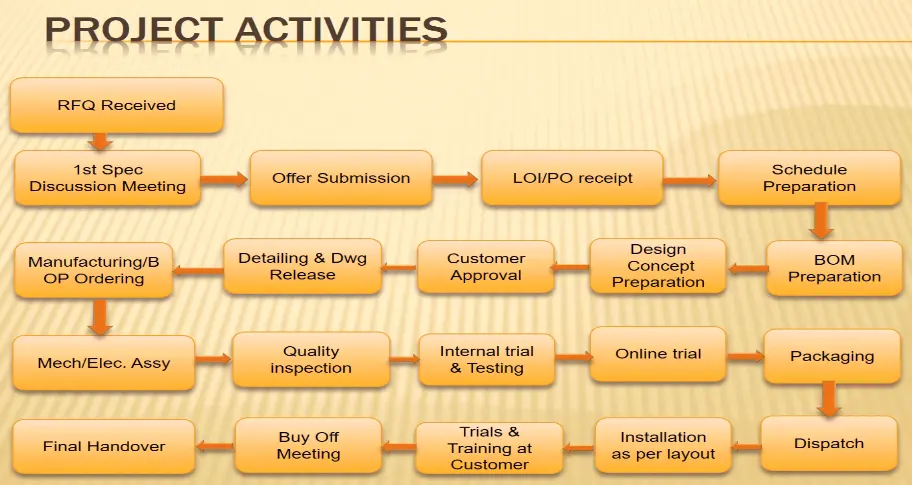
Figure : Process Execution Activity Flow Chart
- RFQ - Request for quotation, customer has gives his requirements (technical specification, dimensions, project cost, etc.) in the form of documents.
- 1st Specefication Discussion Metting - In this customer has briefly discouss their required techical specifications & check wherther they match with company standard projects or not.
- Offer Submission - Comapany send their offer as per customer requirements in the form of documents.
- LOI/PO - After offer recevied by customer they check it offer is as per our requirements or not, then customer will relese the PO.
- Schedule Preparation - Afte PO has received company make schedule preparation, in which they divided the different activities in terms of time.
- BOM Perparation - Bill Of Material is a list of materials, parts required for manufacturing, assembly of a project.
- Disign Concept Preparation - Make design as per customer requirements as they attachted with PO.
- Customer Approval - In that process customer check whether all technical specifaction provided is consider or not. Suggest necessary changes as they want.
- Detailing & Dwg Release - After customer approval is done, design team release the project drawings.
- Manufacturing/BOP odering - After drawing received manufacturing process has been start. Also start ordering Brought out parts.
- Quality Inspection - After manufacturing process completed all parts are sent to the quality inspection department to check whether all parts are make as per drawing (parameters, MOC, treatments, etc.).
- Mech/Elec. Assembly - After quality inspection parts are sent to assembly floor, were all mechanical, electrical parts are assembled as per design.
- Internal Trail & Testing - Checking all the parts are assembled properly or not, all units are in mounted are per design or not. Checking project giving output as per coustomer requirements or not. Checking all required factors are considered or not.
- Online Trail - Once project is set then company start online trail by using control panel, which is gives the commands to machine as per data feed by programmer.
- Packaging - After online trail is successful, projects has to been pack to avoid damage during transportation.
- Dispatch - After packaging process is done, then it will sent to the costomer.
- Installation as per layout - Need to installed project as per layout which is given by customer.
- Trails & Training at Customer - After installation project at customer site customer need to be check wherther it gives output or capable as per requirements or not, wherther it will damage during transportation or not. Customer's staff or machine operator need to be understand how project can run, what are the features, etc.
- Buy off meeting - Customer check all aspects are as per requirements or not. Customer want some modification in that project, similar points are discouss with company.
- Final Handover - After all trails and training project is handover to customer.
2. What are the types of joining processes?
Ans : There are two types of joining process in automotive industry.
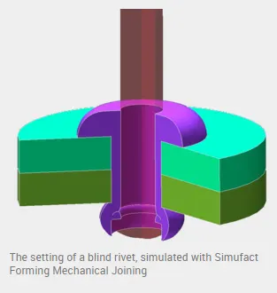
A. Mechanical joining process - In car body constructions, mechanical joining procedures are used to join components of differing materials. This applies to many connections with (and between) steel, aluminum, and fiber composites. Simufact supports simulation of these processes, including self-piercing riveting, blind riveting, flow-hole screwing and clinching.
- Self-piercing riveting
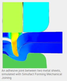
- Blind riveting
- Flow-hole screwing

- Clinching
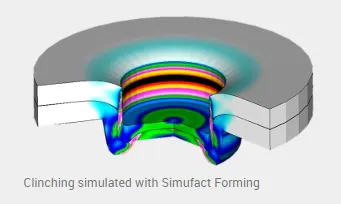
B. Metallurgical joining process - Thermal joining is still the most commonly used joining technique for similar metal-to-metal connections in car bodies, chassis, drivetrains, and exhaust systems. Welding and brazing techniques have a wide range of possible applications, which are usually achievable with low costs, high process robustness, and high joint strength.
- Resistance welding
- Fusion welding
3. What is Resistance Welding & its application in the automotive sector?
Ans :
- Resistance welding involves passing an electric current through the components being joined to heat the interface enough to cause melting of the materials at the interface.
- No filler material is used.
- A clamping force, which is applied during the heating process, holds the components in place until the joint has solidified. Resistance welding processes are used to join metals and include spot welding, seam welding, flash welding, and projection welding.
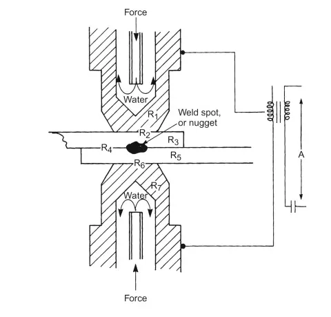
- A diagram of the spot welding process setup is shown in Figure.
Types of resistance welding process-
A. Resistance spot welding -
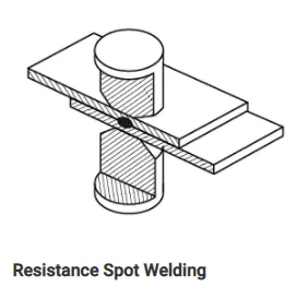
- Spot welding is a resistance welding process for joining metal sheets by directly applying opposing forces with electrodes with pointed tips. The current and the heat generation are localized by the form of the electrodes. The weld nugget size is usually defined by the electrode tip contact area.
- Spot welding is the predominant joining process in automotive industry for assembling the automobile bodies and large components. It is also widely used for manufacturing of furniture and domestic equipment etc.
Advantages of resistance spot welding-
- Short weld time & hence high weld speed.
- Highly adaptable to automation & robotic techniques.
- Typical BIW contains 5000 welds.
- Strength & durability of automobile largely depends on quality of RSW.
B. Resistance seam welding -
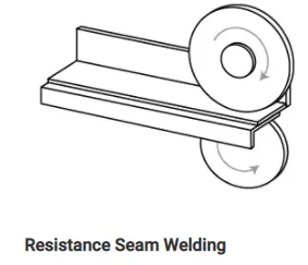
- Seam welding is a resistance welding process for joining metal sheets in continuous, often leak tight, seam joints by directly applying opposing forces with electrodes consisting of rotary wheels. The current and the heat generation are localized by the peripheral shapes of the electrode wheels.
- Seam welding is mostly applied in manufacturing of containers, radiators and heat exchangers etc.
Advantages of resistance seam welding -
- Airtight weld.
- Fast weld process.
- No filler rod required.
Disadvantages of seam welding -
- Limited weld times.
- Weld thickness limitation.
Application -
- Seam welding is mostly used in manufacturing of containers, radiators & heat exchangers.
C. Resistance projection welding -
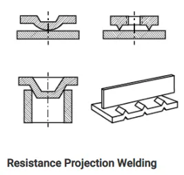
- Projection welding is a resistance welding process for joining metal components or sheets with embossments by directly applying opposing forces with electrodes specially designed to fit the shapes of the workpieces.
- The current and the heat generation are localized by the shape of the workpieces either with their natural shape or with specially designed projection. Large deformation or collapse will occur in the projection part of the workpieces implying high process/machine dynamics.
- Projection welding is widely used in electrical, electronics, automotive and construction industries, and manufacturing of sensors, valves and pumps etc.
Advantages of resistance projection welding-
- Simultaneous operation can be done i.e. more than one welds can be made.
- Projection welding has this advantage that it can weld metals of thickness which is not suitable for spot welding.
- Resistance projection welding is not limited to sheet to sheet joints.
Disadvantages of resistance projection welding -
- All types of metals cannot be welded using projection method. Metal thickness and composition is a big question.
- Projections need to have same heights for a appropriate welding.
Application -
- Resistance Projection welding is used in Automobile sector.
- Projection welding is used in refrigeration works ( mass production of condensers, gratings, racks etc.).
4. What is fusion welding & types of fusion welding with its application in the automotive sector?
Ans : Fusion welding processes can be grouped according to the source of the heat, for example, electric arc, gas, electrical resistance and high energy.
Fusion welding process includes Arc welding process,
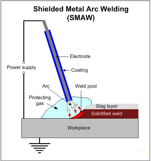
A. Shielded Metal Arc Welding Process -
- Also known as manual metal arc welding (MMA or MMAW), flux shielded arc welding or stick welding. Suitable for welding ferrous and non-ferrous materials in all positions.
- This is the most popular welding process capable to produce a great variety of welds.
- The electrodes are coated with a shielding flux of a suitable composition. The flux melts together with the electrode metallic core, forming a gas and a slag, shielding the arc and the weld pool. The flux cleans the metal surface, supplies some alloying elements to the weld, protects the molten metal from oxidation and stabilizes the arc.
- The slag is removed after Solidification.
Advantages -
-
Simple, portable and inexpensive equipment.
-
Wide variety of metals, welding positions and electrodes are applicable.
-
Suitable for outdoor applications.
Disadvantages -
-
The process is discontinuous due to limited length of the electrodes.
-
Weld may contain slag inclusions.
-
Fumes make difficult the process control.
Application -
- Shipbuilding
- Automotive industries
- Construction industries
- Mechanical industries
B. Metal Inert Gas Welding Process -
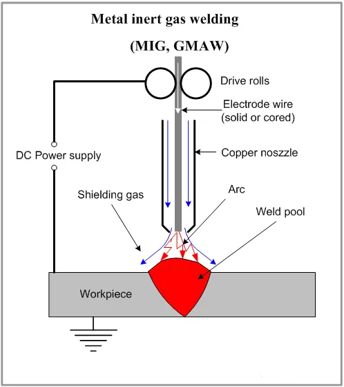
- Metal Inert Gas Welding (Gas Metal Arc Welding) is a arc welding processes, in which the weld is shielded by an external gas (Argon, helium, CO2, argon + Oxygen or other gas mixtures).
- Consumable electrode wire, having chemical composition similar to that of the parent material, is continuously fed from a spool to the arc zone. The arc heats and melts both the work pieces edges and the electrode wire. The fused electrode material is supplied to the surfaces of the work pieces, fills the weld pool and forms joint.
- Due to automatic feeding of the filling wire (electrode) the process is referred to as a semi-automatic. The operator controls only the torch positioning and speed.
Advantages -
-
Continuous weld may be produced (no interruptions).
-
High level of operators skill is not required.
-
Slag removal is not required (no slag).
Disadvantages -
-
Expensive and non-portable equipment is required.
-
Outdoor application are limited because of effect of wind, dispersing the shielding gas.
Application -
- Used for most types of sheet metal welding.
- Fabrication of pressure vessels and steel structures.
- Automotive industry and home improvement industry.
C. Tungsten Inert Gas Welding -
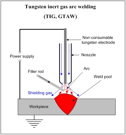
- Tungsten Inert Gas Arc Welding (Gas Tungsten Arc Welding) is a welding processes, in which heat is generated by an electric arc struck between a tungsten non-consumable electrode and the work piece.
- The weld pool is shielded by an inert gas (Argon, helium, Nitrogen) protecting the molten metal from atmospheric contamination.
- The heat produced by the arc melts the work pieces edges and joins them. Filler rod may be used, if required.
- Tungsten Inert Gas Arc Welding produces a high quality weld of most of metals. Flux is not used in the process.
Advantages -
-
Weld composition is close to that of the parent metal.
-
High quality weld structure.
-
Slag removal is not required (no slag).
-
Thermal distortions of work pieces are minimal due to concentration of heat in small zone.
Disadvantages -
-
Low welding rate.
-
Relatively expensive.
-
Requres high level of operators skill.
Applications -
- Aerospace and aircraft construction.
- Automotive industry.
- Auto body repairs.
5. What is the 3-2-1 principle?
Ans -
- Any part which has to be fixed during welding or during machining process has to be fixed, with 3-2-1 principle. Every object has 6 degree of freedom.
- Transition movement along X-axis.
- Transition movement along Y-axis.
- Transition movement along Z-axis.
- Rotational movement along X-axis.
- Rotational movement along Y-axis.
- Rotational movement along Z-axis.
Meaning of 3-2-1.
(3) - Three locator blocks to estabilish part plane. Three locator, or support are place under the work piece. Three locators are usually positioned on the primary locating surface. This restricts one axial movement downward, & 4 radial movements. Together, the three locators restricts 5 degree of freedom.
(2) - Round locating pin in a around hole that defines location in four directions (4 way) perpendicular to the plan previously estabilished. This restricts four axial movements.
(1) - Round locating pin in a slot that defines two of the directions of the other pin (2 way). This restricts two axial movements.
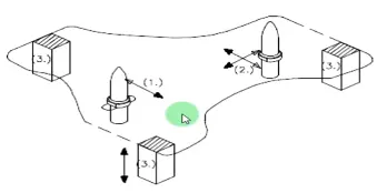
Figure shows the 3-2-1 principle.
6. Define Body coordinate system?
Ans -
- The body coordinate system has widely used in the automotive industry for drawing of body parts, product & process design.
- A coordinate system is a reference system consisting of a set of points, lines & surfaces, used to define the position of points in space in either two or three dimensions.
- In general BCS also known as car line or body line. As shown in fig.
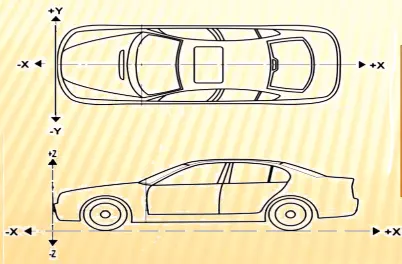
X = Longitudinal direction [(Force & after - F/A) or (Front O line - FOL)].
Y = Transverse direction [(Cross car - C/C) or (Center O line - COL)].
Z = Vertical direction [(Up & Down - U/D) or (Bottom O line - BOL)].
- The origine of the body coordinate system (OX) is define at the front center of a vehicle, it indicate a length of car and the coordinate system (OZ) is below its underbody indicates height of car, and the coordinate system (OY) its starting point of center of car body indicate width of car.
7. Elaborate Body plane system & its essentials.
Ans -
- Body planes are the reference planes in automotive car. This planes are used to define the GD & T for all car parts in a automotive domain.
- Body planes are three mutually perpendicular imaginary planes. These are generally considered to be present at the driver position or sometimes on engine location or at the front end of the car, depending on the customer.
- The measurements from the body planes to the parts are called as bodyline dimensions.
- These body planes are called as,
- FOL front O line
- COL center O line
- BOL body O line
- The measurement along FOL or X axis is called as F/A front Aft.
- The measurement along COL or Y axis is called as C/C cross car.
- The measurement along BOL or Z axis is called as U/DUP down.
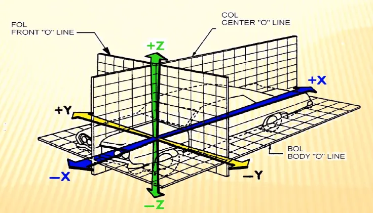
Figure shows the Body Planes.
Essentials for Body Planes -
- It define the exact poostion of each product in the vehicle w.r.t. fixed origin.
- It ensure flawless design for assembly.
- While designing lines, all the desings are carry out relative to the body line.
- It assist in easy location of differnet parts in a vehicle.
- It aims to creating a standardized system.
- It assists in quality checks.