Week 2:- BiW Fixture Basics Challenge
1.What is the process of project execution activity?
RFQ:
In BIW fixture design project begins. It starts with basic requirement or RFQ that we receive from customer. RFQ means request for quotation where in customer give his requirement specification etc. in form of some document or data to study or to work on information include such as technical offer, commercial offer, timeline of project Based on that we have processing to execute project.
1ST SPECIFICATION DISCUSSION MEETING & OFFER SUBMISSION:
In this the documents related technical offer, commercial offer project execution, timeline required to complete the project are prepared. The time required to 3D design, analysis of design, drawing & detailing, manufacturing, assembly & commissioning etc. is considered. Then cost of all operation is considered. By considering these kinds of things the offer is prepared & submitted to customer. Below fig. show document that how technical offer is made.
PO/LOI:
Once we submitted offer customer will study the offer at the same time he will get offer from different supplier & vendor. He compares these technical offers & based on cost whichever suit best for his requirement. Then he will release LOI or PO with its terms & conditions as stated earlier.
SCHEDULE PREPARATION:
In project each activity depends on previous activity. So if previous activity has not completed on time it will cause delay in next activity date is fixed so that it will move further. Each activity has assigned specific time i.e. when activity is starting & when it is ending? So we have some back plan so that final date comes to close final delivery date. There need to be proper scheduling to be done to complete project in time. "On time delivery is one of the major requirements from customer side also customer wants commitment must be follow in respect of time.
BOM PREPARATION:
BOM preparation is listing down of part list which includes bought out parts, vendor parts, and consumable items with quantity of each item. Through BOM preparation material budget will be fixed. 8/0 parts include motor, gear box, cylinder pneumatic & hydraulic valves etc. Also vendor parts include all machined, fabricated parts etc. whereas consumable includes like oil, grease, glue, Loctite etc.
DESIGN. CONCEPT PREPARATION:
Further step is design a concept. A concept is based on all
specification received data from customer as 3D data of car panel, drawing, drawing std.
design standard, manufacturing std. After studying all data design concept is build
CUSTOMER APPROVAL:
As design concept ready then it is send to customer for its approval, It is also known as design approval process (DAP) or customer approval process. In that customer will check that all his specification considers or not in specifications. Whether it is as per technical offer submitted then only he approves prepared concept. Some points will be raised by customer. These changes are updated to design team by project team Design team again work on it some modification or changes are necessary to improve design like clamping need to be improved or this mechanism will work fine, sensor should be of this make These changes are again updated to customer. Once he gave final approval will move further for detailing & drawing, release
DETAILING & DRAWING RELEASE:
In detailing all assemblies broken down into its child parts assembly and segregated into standard as well as manufactured for standard parts own data sheet or specification sheet prepared to purchase it from catalogue motor power, motor current rising torque produced, shaft rpm which suit for our application. For vendor parts of detail should be provided on deg. Like all dimension of part with tolerance, surface fish surface treatment hardness welding note all should be mention on drawings. These drawings finish, surface treatment, hardness, welding note all should be mention on drawing. These drawing are checked & released for manufacturing.
MANUFACTURING & B/O ORDERING:
Manufacturing department will receive all drawing to start manufacturing of items like Mylar, blade, riser, base frame. Also purchase team will place order for B/O parts like motor, gearbox, cylinder & valves. As material get ready, QC team should inspect all part received is as per specification or not otherwise it will create issue later which will waste our time
MECHANICAL & ELECTRICAL ASSEMBLY:
After qc check, parts are available for assembly. A station is integration of all mechanical as well as electrical assembly. Assembly team will do all assembly as per drawing. All stations are built as per layout Then again qc team should be involved for checking assembly as per final drawing, all coordinate dimension should beas per design data.
INTERNAL TRIAL & TESTING:
After approval of qc team, Internal trials & testing started. The first step involves putting assembly in fixture manually to check that it being fix properly, locating pin match with hole, clamping is ok, loading & unloading of part is easy. Also operating height is also checked, it is ergonomically correct. Then start taking trials on fixture for welding feasibility, gun approachability in fixture. Then go for online trial.
ONLINE TRAINING:
After successful of trial next step is online training. In online training has two mode manual & automated. In online trial system is run through control panel. All sensor, actuator, motor current & temperature, noise, all alarm, also safety should be tested. All process must be executed as per sequence also cycle time meet. In online training system run for certain cycle & actual production taken to ensure system run successfully.
PACKAGING:
After trial get successful customer give approval to dispatch system To dispatch whole system needs to disassemble station wise & pack properly. Delicate material should be packed properly otherwise there is chance of damage aesthetically or functionally during transportation During packaging labeling, special handling instruction should be pasted on particular parts to convey message of taking care during handling & transportation by air
DISPATCH:
All material transported at customer site through tracks, container, and ships or Installations: All system is assembled & installed at customer and as per layout approved Initially in DAP. All station, robots, conveyor mounted as per distance specified in layout Robot arm should be reachable to station pick & drop point. It shouldn't foul with other Robot arm should be reachable to station, pick & drop point. It shouldn't foul with other equipment. Also some adjustment should be provided for levelling purpose at robot conveyor base, station base frame like levelling stud to align with other equipment Layout is always specified at the time of initial design stage & it has to be approved by customer.
TRIAL & TRAINING AT CUSTOMER END:
Once installation is done trial start at customer end. So there will be production trial, online trial. Production trial is necessary because at the time of designing fixture, it also committed no of unit that will be manufactured from that fixture also whether it is meeting quality, bench mark or not. Also in technical offer it is committed that there will be 100 units per 8hrs shift will manufactured from that fixture with weld quality. So during production trial fixture capability will be ensured. Once this goal is achieved then there will be training to operator, staff member, engineers to let them to understand how process is working?
BUY OFF MEETING:
Once training is completed there is buy off meeting between customer & project team with discussion on if other things need to be incorporated, anything missing that described in LO/PO or offer submission. Then customer will raise point or sometimes customer wants modification that will lead to extra quotation, extra costing according work is done as per buy of meeting
FINAL HANDOVER:
Once all points raised by customer will be closed then all will go for final handover All data technical manual soft hard documents will submit to customer. These are main project activity
2.What are the types of joining processes?
Joining processes include welding, brazing, soldering, mechanical fastening, and adhesive bonding. Mechanical fastening can be used to provide either temporary or permanent joints, while adhesive bonding, welding, brazing, and soldering processes are mainly used to provide permanent joints. Mechanical fastening and adhesive bonding usually do not cause metallurgical reactions. Consequently, these methods are often preferred when joining dissimilar combinations of materials and for joining polymer-matrix composites that are sensitive to extreme heat. Welding processes are divided into two broad classes: fusion welding and solid-state welding.
Joining includes welding, brazing, soldering, adhesive bonding of materials.
They produce permanent joint between the parts to be assembled.
They cannot be separated easily by application of forces.
They are mainly used to assemble many parts to make a system.
Welding is a metal joining process in which two or more parts are joined
or coalesced at their contacting surfaces by suitable application of heat
or/and pressure.
Sometimes, welding is done just by applying heat alone, with no pressure
applied
In some cases, both heat and pressure are applied; and in other cases only
pressure is applied, without any external heat.
In some welding processes a filler material is added to facilitate
coalescence(Joining)
Types:
1.Metallurgical
2.Mechanical
Welding:
Welding is process of permanently joining material welding joins different metal/ alloys with a number of processes in which heat is supplied either electrically or by means of torch. Welding is done by application of heat or both heat & pressure, Pressure may be employed, but this is not in many processes essential. The welding process involves applying heat to the work piece. The heat applied should be such that the work piece should melt, i.e., the temperature at which welding is done, should be more than the melting point of the work piece to be welded. Welding is a fabrication or sculptural process that joins materials, usually metals or thermoplastics, by using high heat to melt the parts together and allowing them to cool, causing fusion Welding is distinct from lower temperature metal-joining techniques such as brazing and soldering, which do not melt the base metal In addition to melting the base metal, a filler material is typically added to the joint to form a pool of molten material (the weld pool) that cools to form a joint that, based on weld configuration (butt, full penetration, fillet, etc.), can be stronger than the base material (parent metal). Pressure may also be used in conjunction with heat or by itself to produce a weld Welding also requires a form of shield to protect the filler metals or melted metals from being contaminated or oxidized. Many different energy sources can be used for welding including a gas flame (chemical), on electric arc (electrical), a laser, an electron beam friction and ultrasound While often an industrial process, welding may be performed in many different environments, including in open air, underwater and in outer space Welding is a hazardous undertaking and precautions are required to avoid bums electric shock vision damage, inhalation of poisonous gases and fumes, and exposure to intense ultraviolet radiation
Brazing
It is a joining process in which a filler metal is melted and distributed by capillary
action between the faying (contact) surfaces of the metal parts being joined.
- In brazing, the filler metal has a melting temperature above 450°C, but below the
melting point of base metals to be joined.
- Join produced by this welding is stronger than soldering.
- This process offers better corrosion resistance.
- Filler used in brazing include Cu and Cu alloys, silver alloys and Al alloys.
- In this process heating is done by torch, furnace, induction, resistance, bath
dipping infrared techniques.
Advantages of brazing
- Brazing can be used to join a large variety of dissimilar metals.
- Pieces of different thickness can be easily joined by brazing
- Thin-walled tubes & light gauge sheet metal assemblies not joinable by welding can be joined by brazing.
- Complex & multi-component assemblies can be economically fabricated with the help of brazing.
- Inaccessible joint areas which could not be welded by gas metal or gas tungsten arc spot or seam welding can be formed by brazing.
Applications:
1)Automobile – Joining Tubes
2) Pipe/Tubing joining (HVAC)
3) Electrical equipment - joining wires
4) Jewellery Making
Soldering
Soldering is similar to brazing and can be defined as a joining process in which a filler metal with melting point not exceeding 450°C is melted and distributed by capillary action between the faying surfaces of the metal parts being joined. As in brazing, no melting of the base metals occurs, but the filler metal wets and combines with the base metal to form a metallurgical bond.
Filler metal, called Solder, is added to the joint, which distributes itself between the closely fitting parts.
- Strength of the joint is weak
- Corrosion resistance is less
SOLDER: Alloys of Tin and Lead. Tin is chemically active at soldering
temperatures and promotes the wetting action required for successful joining.
Applications:
1) Printed Circuit Board (PCB) manufacture
2) Pipe joining (copper pipe)
Easy to solder: copper, silver, gold
Difficult to solder: aluminium, stainless steels
Adhesive bonding:
Adhesive bonding (also referred to as gluing or glue bonding) describes a water bonding technique with applying an intermediate layer to connect substrates of different types of materials. Those connections produced can be soluble or insoluble. The commercially available adhesive can be organic or inorganic and is deposited on one or both substrate surfaces. Adhesives, especially the well-established SU-8, and benzocyclobutene (BCB), are specialized for MEMS or electronic component production. The procedure enables bonding temperatures from 1000 °C down to room temperature. The most important process parameters for achieving a high bonding strength are adhesive material, coating thickness, bonding temperature, processing time, chamber pressure, tool pressure
Adhesive bonding has the advantage of relatively low bonding temperature as well as the absence of electric voltage and current Based on the fact that the wafers are not in direct contact, this procedure enables the use of different substrates, silicon, glass metals and other semiconductor materials A drawback is that small structures become wider during patterning which hampers the production of an accurate intermediate layer with tight dimension control. Further, the possibility of corrosion due to out-gassed products. thermal instability and penetration of moisture limits the reliability of the banding process. Another disadvantage is the missing possibility of hermetically sealed encapsulation due to higher permeability of gas and water molecules while using organic adhesives Below figure shown for an additional information
Diffusion bonding:
Diffusion bonding or diffusion welding is a solid-state welding technique used in metalworking, capable of joining similar and dissimilar metals. It operates on the principle of solid-state diffusion, wherein the atoms of two solid, metallic surfaces intersperse themselves over time. This is typically accomplished at an elevated temperature, approximately 50-70% of the absolute melting temperature of the materials. Diffusion bonding is usually implemented by applying high pressure, in conjunction with necessarily high temperature, to the materials to be welded, the technique is most commonly used to weld sandwiches of alternating layers of thin metal foil, and metal wires or filaments Currently, the diffusion bonding method is widely used in the joining of high strength and refractory metals within the aerospace and nuclear industries.
2.Mechanical joining
Mechanical joining is a process for joining parts through clamping or fastening using screws, bolts of rivets Advantages of mechanical joining include versatility, ease of use, and the option to dismantle the product in cases where regular maintenance requires it The ability to join dissimilar materials is another benefit. A drawback of using mechanical joining is the lack of a continuous connection between parts, because the joint is achieved through discrete points. Also, holes created for joining are vulnerable to fractures and corrosion
Mechanical joining-also called joining by forming - has become interesting for the automotive industry due to the request to reduce fuel consumption and thereby emissions order to reduce weight on the car body, the usage of lightweight materials in the body white application has increased. This includes aluminium, high-strength steel alloys, prymers and composites. Here the different type of mechanical joining becomes important. All mechanical joining methods are cold forming techniques. One general Benes for all mechanical joining methods is the mobility of the material after joining At the same time mechanical joining offers an impressive strength.
Mechanical fastening:
The joining of material combinations which cannot be easily welded such as pre-painted steel or very dissimilar metal. Ex. Al application in auto body makes use of mechanical fastening to overcome the poor inherent weld ability of AL
The joining of materials in application where high fatigue life is critical compared to static strength.
The joining of materials where high tool life is of relative importance screw, bolts etc.
Self-piercing riveting
Self-piercing riveting is high speed mechanical fastening for point joining sheet material, typically steel & aluminium alloys. It is single step technique generally using a semi tubular rivet to clinch the sheet in mechanical joint. There is also process variant which utilizes solid rivets
As name suggest pre drilled hole are not required allowing joint to be made rapidly in one operation The process cycle is shown in cross section below
Hemming & seaming process:
Hemming & seaming are two similar metal working processes in which a sheet metal edge is rolled over on to itself. Hemming is process in which edge is rolled flush to itself, while seam joins edges of two materials. Hems are commonly used to reinforce an edge, hide burrs and rough edges, and improve appearance Seams are commonly used in the food industry on canned goods, on amusement park cars, in metal rooting (with a roof seamer). and in the automotive industry. The process for both hemming and seaming are the same, except that the tonnage requirement is greater for seaming. The process starts by bending the edge to an acute angle. A flattening die is then used to flatten the hem. Below figure illustrate hem formation.
3.What is Resistance Welding & its application in the automotive sector?
RESISTANCE WELDING:
Resistance welding is one of the oldest of electric welding process in use by industry today. The weld is made by a combination of heat, pressure and time. As the name resistance welding implies, it is the resistance of the material to bewelded to causes current to flow and localized heating in the part. The pressure exerted by the tongs and electrode tips, through which the current flows, hold the parts to be welded in intimate contact before, during and after the welding current time cycle. The required amount of time to current to flow in the joint is determined by material thickness and type, the amount of current flowing and the cross-section area of the welding tip contact surfaces.
Practically all metals can be resistance welded and the operation is quite fast.
- Weld nugget is generated by this process
- RW uses no shielding gases, flux, or filler metal.
- electrodes that conduct electrical power to the process are non-consumable
Current: 5000 to 20,000 A
Voltage: < 10V>
Duration of current: 0.1 to 0.4 s (in spot-welding operation)
- Resistance in the welding circuit is the sum of (1) resistance of the electrodes,
(2) resistances of the sheet parts, (3) contact resistances between electrodes and
sheets.
Resistance at the welding surfaces depends on surface finish, cleanliness,
contact area, force. No paint, oil, dirt, and other contaminants should be present
to separate the contacting surfaces.
Advantages:
no filler rod required, high production rates, automation and mechanization is possible.
Disadvantages: restricted to lap joint, costly equipment
Resistance spot welding
Importance: a typical car body has got app. 15, 000 spot welds.
In this process, the fusion of electrodes is done by electrodes having opposing charges at
one location. The sheet thickness has to be less than 3 mm for a good spot weld.
The shape of electrode tip is important like round, hexagonal, square etc. The nugget
shape will be app. 5-10 mm in this case.
Electrodes in RSW: (i) Copper based, (ii) Refractory metal (Cu, Tungsten
combinations)
Steps in spot welding
This is the simplest form of resistance welding and does not possesses any problem for welding sheets ranging up to 12.5 mm in thickness.
- For best results the surfaces to be welded must be free from scales and foreign matter.
- Spot welding machines are available in three different types: stationary single spot, portable single spot and multiple spot welding machines.
- Stationary single spot machines can be further classified into rocker arm type and direct pressure type.
Resistance Seam Welding:
- In principle, seam welding is similar to spot welding except that it uses disc shaped electrodes as
- Unlike spot welding the disc shaped electrodes are not separated after each weld but maintain a continuous pressure over the work pieces.
- Two common types of seam weld are Lap seam welding and Butt seam welding.
- The electrode current is timed to flow in pulses so that a row of welds is produced along the interface.
4.What is fusion welding & types of fusion welding with its application in the automotive sector?
Fusion welding processes can be grouped according to the source of the heat, for example, electric arc, gas, electrical resistance and high energy.
These processes include:
Arc Welding Processes - with the most common processes being:
Shielded Metal Arc Welding (SMAW), also known as manual metal arc welding (MMA or MMAW), flux shielded arc welding or stick welding. Suitable for welding ferrous and non-ferrous materials in all positions.
Metal Inert Gas Welding (MIG)
also known as Gas Metal Arc Welding (GMAW). MIG and MAG welding are the most common arc welding processes, in which an electric arc forms between a consumable wire electrode and the work piece leading them to melt and join. Both use a shielding gas to protect the weld from airborne contaminants, or oxidation in the case of MIG welding.
Tungsten Inert Gas welding (TIG)
also known as Gas Tungsten Arc Welding (GTAW). This arc process uses a non-consumable tungsten electrode to create the arc between the electrode and the base plate. An inert shielding gas is used to protect from oxidation or other atmospheric contamination. This process can be used autogenously on thin parts, but will require the addition of a wire, rod, or consumable to be added for thicker parts.
Plasma Arc Welding (PAW)
This process uses an electric arc created between an electrode and the torch nozzle. The electric arc ionises the gas (usually argon) in the chamber creating what is called a 'plasma.' It is then forced through a fine bore copper nozzle that constricts the arc and directs it to the work piece, allowing the plasma arc to be separated from the shielding gas (which is usually made from a mixture of argon and hydrogen).
Submerged Arc Welding (SAW)
This frequently-used arc welding process uses a continuously-fed consumable electrode and a blanket of fusible flux which becomes conductive when molten and provides a current path between the work piece and the electrode. The flux also prevents spatter and sparks while suppressing ultraviolet radiation and fumes.
Flux Cored Arc Welding (FCAW). Developed as an alternative to SMAW, this process uses a continuously fed consumable electrode with a flux and a constant voltage or constant current power supply. Sometimes using a shielding gas this process can also just use the flux to provide protection from the atmosphere.
5.What is the 3-2-1 principle?
A fundamental concern in metalworking is locating the part to be machined, punched, bent, or stamped relative to the work platform (fixture). For example, a CNC machine tool starts its process at a specific point relative to the fixture and proceeds from there. Hence, the accuracy with which a part is machined is quite dependent on the accuracy with which it is positioned in the fixture.
Accurate locating of not just one part, but each and every part that is loaded into the fixture is crucial. Any variation in part location on the fixture adds to the dimensional tolerance that must be assigned to the finished parts.
Additionally, the method of supporting and securing the part in the fixture affects not only dimensional tolerances, but surface finishes as well. This is true because improper supporting or clamping can temporarily or permanently deform the part. Hence, techniques for supporting and clamping must be considered together with the method of locating in order to assure repeatability from part-to-part.
Locating of a part to be machined is a three-step process:
1. Supporting
2. Locating (positioning)
3. Holding (clamping)
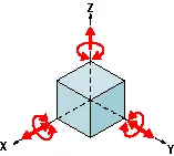
The Locating Process: Degrees of Freedom
In order to completely specify the position in space of a three-dimensional
object (such as the cube that’s shown), we refer to six coordinates:
- Translational position along the X-axis
- Translational position along the Y-axis
- Translational position along the Z-axis
- Rotational position about the X-axis
- Rotational position about the Y-axis
- Rotational position about the Z-axis
These six coordinates are known as the six degrees of freedom of a three-dimensional object. As the double-headed arrows indicate, the translational and rotational positions can vary in either direction with respect to each of the three axes.
To completely prevent movement, all six degrees of freedom must be restricted.
The Locating Process: 3-2-1 Method
We have two objectives when mounting a part in a fixture for machining:
1. Accurately position the part at the desired coordinates.
2. Restrict all six degrees of freedom so that the part cannot move.
A widely used method of accomplishing these two objectives uses the 3-2-1 principle, so-called because it entails three steps that employ three, then two, then one fixed points of known location. Since that adds up to six fixed points, it’s also known as the six point method.
In the three steps of the 3-2-1 method, three mutually perpendicular planes, called datum planes, are introduced, one at each step. These three planes define the workpiece position, and together with opposing clamping forces fully constrain the part. Let’s take a look at the details of the 3-2-1 method.
First Plane
Geometry tells us that three points are required to define a plane. This is the "3" in 3-2-1. So, three specific points are used to define the first plane. Fewer than three points cannot define a plane, and in the real world dimensional tolerances mean that four or more points will not be coplanar. A real-world, less than ideally perfect part placed on four or more reference points will, in fact, rest on only three of the points due to its less than perfect surface. Different parts may rest on different combinations of three points, resulting in variation between finished parts. A stool can be used to illustrate this concept. A two-legged stool would certainly be unstable. A three-legged stool sits rock-solid. A four-legged stool is often found to rock. In the illustration, a three dimensional part, represented by a cube, is placed on a datum plane defined by three support points. The part’s six degrees of freedom have now been reduced to three. It can still move along the X or Y axes, and it can still be rotated about the Z axis. (The part cannot move along the Z axis because it is held against the plane by clamping force.
Second Plane
A second plane, if it is perpendicular to the first, can be defined by two points, the "2" in 3-2-1. The part is now constrained to one degree of freedom: movement along the Y axis. (The part cannot move along the X or Z axes because it is held against the planes by clamping force.)
Third Plane
A third plane, if it is perpendicular to both of the first two planes, can be defined by one point, the "1" in 3-2-1. The part is now entirely constrained. It cannot move along or rotate about the X, Y, or Z axes. (Remember that the part is held against each of the three planes by clamping force.)
Repeatability
Repeatability is a paramount concern. It means that each part should be nearly identical to each other part coming off the same fixture. "Nearly identical" actually has a specific, quantifiable meaning: key dimensions of all parts produced on the same fixture must fall within defined tolerances.
In order to stay within tolerances, it’s best if the workpiece surfaces intended to contact the support points are machined. Cast surfaces are usable, but they tend to create tolerance problems. Machined holes are the number one choice, because two machined holes can be used to eliminate all but one degree of freedom.
The next best feature to use for consistent locating is machined surfaces at right angles. The "machined surface" desired here can simply be a tab or small flat specifically included for locating purposes.
Repeatability is achieved through application of the 3-2-1 method to the three aspects of the locating process:
1. Supporting
2. Locating (positioning)
3. Holding
Supporting
- The part is supported from "below" with reference to the Z axis. (Introduction of the first reference plane.)
- Gravity positions the part against the support locator.
- Provide adjustable auxiliary support points as needed to prevent deflection.
- Vertical location with respect to the fixture is now established
- The part is positioned horizontally, in the X-Y plane. (Introduction of the second and third reference planes.)
Holding
- The part is clamped against fixed locators. Therefore, a known and unvarying position of the part is maintained with respect to the X, Y, and Z axes.
- One strap clamp or clamp arm will restrict the workpiece in three dimensions due to friction between the workpiece and clamp. However, friction alone may not be enough to prevent the workpiece from moving during machining.
- Cutting forces will not move a properly supported and clamped part.
Locating
- The part is positioned horizontally, in the X-Y plane. (Introduction of the second and third reference planes).
Summary: Clamping Rules of Thumb
- Define three reference planes on the workpiece and fixture.
- Provide one opposing clamping force opposite each plane to restrict movement.
- When in doubt, rely on additional cylinders to take up uncertainty.
6.BODY COORDINATE SYSTEM
- The body coordinate system is widely used in the automotive industry for drawing of body parts, products and process design.
- A coordinate system is a reference system consisting of a set of points,lines and surfaces,used to define the positions of points in space in either two or three dimensions.
- In general BCS is also called as car line and body line.
- Maintaining X, Y & Z coordinates in fixture is a very important factor. We should try that the co-ordinates of locating and clamping points should not be in three decimal. (e.g.X=100.124, Y=245.127, Z=450.458)
- They should be whole nos. or maximum upto 1 decimal. Once these co-ordinates are maintained automatically the BIW base structure is maintained.
X = Longitudinal direction[(Fore and After- F/A) or (Front O Line- FOL)]
Y = Transverse direction[(Cross car- C/C) or (Centre O Line- COL)]
Z = Vertical direction[(Up and Down- U/D) or (Bottom O Line- BOL)
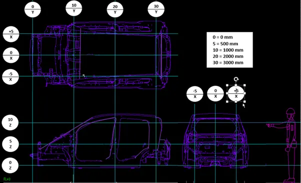
X(width of BIW) - OX is Body Center Line
Y(length of BIW) - OY is Near Front Bumper
Z(Height of BIW) - OZ is about Center of Wheel
- The above schematic figure shows the basic car geometry system used widely to specify the position of parts which is to be assembled to the car body. From the first part of the production line this coordinate system is used to specify its position.
- According to the CAD data some references are specified to the car body on the basis of which each and every part of the car body is assembled respectively.
- The fixture position is also defined with reference of these coordinate system. The fixture is installed on the basis of these reference point defined by CAD data according to which the fixture base plate and the accessories are installed..
- Each and every parts measurement is done with reference to this coordinate system. The deviation in the assembly of car body and the components is shown with respect to these coordinates. An individual part measurement is also done with respect to these coordinate system.
- Accuracy of the BIW is also defined by the final measurement report which are based on these coordinate system.
7. Elaborate Body Plane System & its essentials.
BODY PLANE SYSTEM
- Body planes are reference planes in an automotive car. These planes are used to define the GD&T of all parts in an automotive domain.
- Body planes are 3 mutually perpendicular imaginary planes.
- The measurement from body plane to parts are called body plane dimensions.
- The planes are generally considered to be present in the driver position or sometimes at engine location or at the front end of the car depending on the customer.
- The measurement from the body planes to the parts are called the body line dimensions.
X = Longitudinal direction[(Fore and After- F/A) or (Front O Line- FOL)]
Y = Transverse direction[(Cross car- C/C) or (Centre O Line- COL)]
Z = Vertical direction[(Up and Down- U/D) or (Bottom O Line- BOL)
Fig shows: Typical body plane of a car
Body line dimensions are essentials for the following reasons:
- It defines exact position of each product in the vehicle with respect to a fixed origin.
- It ensures flawless design for assembly.
- While designing lines, all the designs are carried out relative to the bodylines viz.fixtures,turntables,etc.,
- It assists in easy location of different parts in the vehicle.
- It aims in creating a standardized system.
- It assists in quality check.