3. What is Resistance Welding & its application in the automotive sector?
Resistance welding is a type of welding that uses heat generated by the resistance of the materials being joined to melt them together. It is a versatile process that can be used to join a wide variety of materials, including steel, aluminum, and copper.
There are many different types of resistance welding, but the most common are:
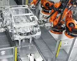
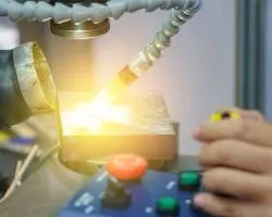
- Spot welding: Spot welding is used to join two pieces of metal by applying a high current between the two pieces for a short period of time. The heat generated by the current melts the metal at the contact points, creating a strong weld. Spot welding is used extensively in the automotive industry to join body panels and other components.
Spot welding in automotive sector
- Seam welding: Seam welding is similar to spot welding, but the current is applied continuously as the two pieces of metal are moved together. This creates a continuous weld along the joint. Seam welding is used to join long lengths of metal, such as hoses and pipes.
Seam welding in automotive sector
- Projection welding: Projection welding is a variation of spot welding that uses projections on the two pieces of metal to increase the contact area and the amount of heat generated. This allows for stronger welds to be made. Projection welding is used to join sheet metal components in the automotive industry.
Projection welding in automotive sector
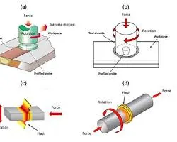
- Flash welding: Flash welding is used to join two pieces of metal by creating an arc between the two pieces. The heat generated by the arc melts the metal and creates a flash of molten metal. The two pieces of metal are then pressed together, fusing the molten metal together. Flash welding is used to join thick pieces of metal, such as steel beams.
Flash welding in automotive sector
Resistance welding is a fast and efficient process that can be used to join a wide variety of materials. It is also a relatively inexpensive process, making it a popular choice for the automotive industry.
In the automotive sector, resistance welding is used to join a wide variety of components, including body panels, chassis parts, and engine components. It is a versatile process that can be used to join a variety of materials and thicknesses. Resistance welding is also a relatively low-cost process, making it a cost-effective way to join automotive components.
Here are some of the advantages of using resistance welding in the automotive sector:
- Fast and efficient: Resistance welding is a fast and efficient process, which can help to reduce production time and costs.
- Versatile: Resistance welding can be used to join a variety of materials and thicknesses, making it a versatile process for the automotive industry.
- Low-cost: Resistance welding is a relatively low-cost process, which can help to reduce the overall cost of manufacturing automotive components.
- Strong and reliable: Resistance welds are typically strong and reliable, making them a good choice for applications where strength and durability are important.
Here are some of the limitations of using resistance welding in the automotive sector:
- Heat affected zone: The heat generated by resistance welding can create a heat affected zone (HAZ) around the weld. The HAZ can weaken the material, so it is important to minimize the size of the HAZ.
- Distortion: Resistance welding can cause distortion of the materials being joined. This can be minimized by using proper welding techniques and by using fixtures to hold the materials in place.
- Contamination: The heat generated by resistance welding can vaporize contaminants from the materials being joined. These contaminants can contaminate the weld, so it is important to use clean materials and to take steps to prevent contamination.
4. What is fusion welding & types of fusion welding with its application in the automotive sector?
Fusion welding is a type of welding that joins two pieces of metal by melting them together. The heat is generated by an electric arc, a gas flame, or a laser beam. The molten metal then cools and solidifies, forming a strong joint.
There are many different types of fusion welding, but the most common are:
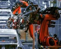
- Gas metal arc welding (GMAW): GMAW is a process that uses a consumable wire electrode to create an arc. The arc melts the wire and the base metal, and the molten metal is then transferred to the base metal by a shielding gas. GMAW is a versatile process that can be used to weld a wide variety of materials.
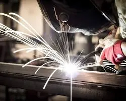
Gas metal arc welding (GMAW) in automotive sector
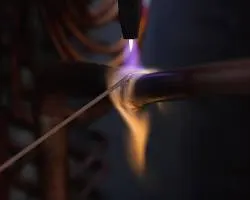
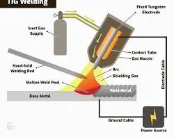
- Gas tungsten arc welding (GTAW): GTAW is a process that uses a non-consumable tungsten electrode to create an arc. The arc melts the base metal, and the molten metal is then transferred to the base metal by a shielding gas. GTAW is a precision process that is often used to weld thin materials or materials with complex shapes.
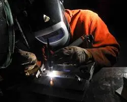
Gas tungsten arc welding (GTAW) in automotive sector
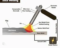
- Shielded metal arc welding (SMAW): SMAW is a process that uses a consumable metal electrode to create an arc. The arc melts the electrode and the base metal, and the molten metal is then transferred to the base metal by a flux coating on the electrode. SMAW is a versatile process that is often used to weld thick materials.
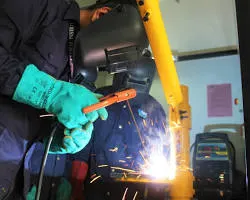
Shielded metal arc welding (SMAW) in automotive sector
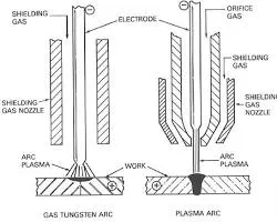
- Plasma arc welding (PAW): PAW is a process that uses a plasma arc to melt the base metal. The plasma arc is created by forcing an inert gas through a small orifice. PAW is a precise process that is often used to weld thin materials or materials with complex shapes.
Plasma arc welding (PAW) in automotive sector
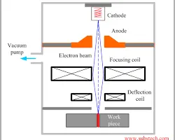
- Laser beam welding (LBW): LBW is a process that uses a laser beam to melt the base metal. The laser beam is focused on the weld area, which melts the base metal. LBW is a very precise process that can be used to weld thin materials or materials with complex shapes.
Laser beam welding (LBW) in automotive sector
Fusion welding is a versatile process that is used in a wide variety of applications, including the automotive sector. In the automotive sector, fusion welding is used to join a wide variety of components, including body panels, chassis parts, and engine components. It is a versatile process that can be used to join a variety of materials and thicknesses. Fusion welding is also a relatively low-cost process, making it a cost-effective way to join automotive components.
Here are some of the advantages of using fusion welding in the automotive sector:
- Strong and reliable: Fusion welds are typically strong and reliable, making them a good choice for applications where strength and durability are important.
- Versatile: Fusion welding can be used to join a variety of materials and thicknesses, making it a versatile process for the automotive industry.
- Low-cost: Fusion welding is a relatively low-cost process, which can help to reduce the overall cost of manufacturing automotive components.
- Automated: Fusion welding can be automated, which can help to improve production efficiency.
Here are some of the limitations of using fusion welding in the automotive sector:
- Heat affected zone: The heat generated by fusion welding can create a heat affected zone (HAZ) around the weld. The HAZ can weaken the material, so it is important to minimize the size of the HAZ.
- Distortion: Fusion welding can cause distortion of the materials being joined. This can be minimized by using proper welding techniques and by using fixtures to hold the materials in place.
- Contamination: The heat generated by fusion welding can vaporize contaminants from the materials being joined. These contaminants can contaminate the weld, so it is important to use clean materials and to take steps to prevent contamination.
5. What is the 3-2-1 principle?
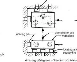
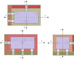
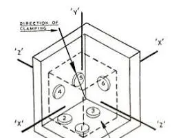
The 3-2-1 principle is a method of locating a workpiece in a fixture that ensures that the workpiece is held in the correct position and orientation. The principle states that three locating pins should be used to locate the workpiece in the X-Y plane, two locating pins should be used to locate the workpiece in the Z-direction, and one locating pin should be used to prevent the workpiece from rotating.
The 3-2-1 principle is a simple and effective way to ensure that the workpiece is held in the correct position and orientation. It is commonly used in manufacturing, assembly, and inspection.
According to the 3-2-1 principle, we would use three locating pins to locate the part in the X-Y plane. These pins would be located in the center of the flat face and in the center of each hole. We would then use two locating pins to locate the part in the Z-direction. These pins would be located on the side of the part, one above each hole. Finally, we would use one locating pin to prevent the part from rotating. This pin would be located in the center of the flat face.
example of the 3-2-1 principle in action with pictures:
The workpiece is a rectangular block with two holes on one side. The three locating pins are located in the center of the flat face and in the center of each hole. The two locating pins are located on the side of the part, one above each hole. The one locating pin to prevent the part from rotating is located in the center of the flat face.
The 3-2-1 principle can be applied to any workpiece, regardless of its shape or size. It is a simple and effective way to ensure that the workpiece is held in the correct position and orientation.
Here are some other examples of the 3-2-1 principle in action:
- Machining a part with a cylindrical surface: The three locating pins would be located in the center of the cylindrical surface. The two locating pins would be located on the side of the part, one above and one below the cylindrical surface. The one locating pin to prevent the part from rotating would be located in the center of the cylindrical surface.
- Assembling a car door: The three locating pins would be located in the center of the door frame. The two locating pins would be located on the side of the door, one above and one below the door frame. The one locating pin to prevent the door from rotating would be located in the center of the door frame.
- Inspection of a machined part: The three locating pins would be located in the center of the part's features. The two locating pins would be located on the side of the part, one above and one below the features. The one locating pin to prevent the part from rotating would be located in the center of the part.
The 3-2-1 principle is a versatile and effective way to ensure that workpieces are held in the correct position and orientation during manufacturing, assembly, and inspection.
6. Define Body coordinate system?
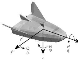
In physics and engineering, a body coordinate system is a coordinate system that is attached to a rigid body. The body coordinate system moves with the rigid body, so the position and orientation of the body can be described by the coordinates of the origin of the body coordinate system.
The body coordinate system is typically used in problems involving the motion of rigid bodies. In these problems, the position and orientation of the body are important variables, and the body coordinate system provides a convenient way to describe these variables.
Concept of a body coordinate system:
The body coordinate system can be defined in any way that is convenient for the problem being solved. However, it is typically defined so that the origin of the body coordinate system is located at a point of interest on the body, and the axes of the body coordinate system are aligned with the principal axes of inertia of the body.
The body coordinate system is often used in conjunction with the inertial coordinate system. The inertial coordinate system is a coordinate system that is fixed in space, and it is not attached to any particular body. The relationship between the body coordinate system and the inertial coordinate system can be described by a transformation matrix.
The transformation matrix can be used to convert coordinates from the body coordinate system to the inertial coordinate system, and vice versa. This is useful for problems involving the motion of rigid bodies, as it allows the motion of the body to be described in terms of the inertial coordinate system, which is a fixed reference frame.
Here are some of the advantages of using a body coordinate system:
- Convenient: The body coordinate system can be defined in any way that is convenient for the problem being solved. This can make it easier to solve the problem.
- Accurate: The body coordinate system is attached to the rigid body, so it moves with the body. This means that the coordinates of the origin of the body coordinate system accurately describe the position of the body.
- Robust: The body coordinate system is not affected by changes in the orientation of the body. This makes it a robust way to describe the motion of the body.
Here are some of the disadvantages of using a body coordinate system:
- Not universal: The body coordinate system is not a universal coordinate system. This means that it cannot be used to describe the motion of all rigid bodies.
- Complicated: The transformation matrix between the body coordinate system and the inertial coordinate system can be complicated to calculate.
- Not intuitive: The body coordinate system may not be intuitive for some people. This can make it difficult to use the body coordinate system to solve problems.
7. Elaborate Body plane system & its essentials.
A body plane system is a set of three mutually perpendicular planes that are attached to a rigid body. The body plane system moves with the rigid body, so the orientation of the body plane system relative to a fixed reference frame is constantly changing.
The three planes of the body plane system are typically named the XY plane, the YZ plane, and the XZ plane. The XY plane is the plane that contains the X-axis and the Y-axis. The YZ plane is the plane that contains the Y-axis and the Z-axis. The XZ plane is the plane that contains the X-axis and the Z-axis.
The body plane system is often used in conjunction with the inertial coordinate system. The inertial coordinate system is a coordinate system that is fixed in space, and it is not attached to any particular body. The relationship between the body plane system and the inertial coordinate system can be described by a transformation matrix.
The transformation matrix can be used to convert coordinates from the body plane system to the inertial coordinate system, and vice versa. This is useful for problems involving the motion of rigid bodies, as it allows the motion of the body to be described in terms of the inertial coordinate system, which is a fixed reference frame.
The essentials of the body plane system are:
- The body plane system is attached to the rigid body. This means that the body plane system moves with the rigid body.
- The three planes of the body plane system are mutually perpendicular. This means that they intersect at right angles.
- The orientation of the body plane system relative to a fixed reference frame is constantly changing. This is because the rigid body is moving.
- The body plane system can be used to describe the motion of the rigid body. This is done by converting coordinates from the body plane system to the inertial coordinate system, and vice versa.
The body plane system is a versatile and useful tool for describing the motion of rigid bodies. It is simple to understand and use, and it can be used to solve a wide variety of problems.
Here are some of the applications of the body plane system:
- Engineering: The body plane system is used in engineering to analyze the motion of machines and structures.
- Aerodynamics: The body plane system is used in aerodynamics to analyze the flow of air around objects.
- Biomechanics: The body plane system is used in biomechanics to analyze the motion of the human body.
- Robotics: The body plane system is used in robotics to control the motion of robots.