Week 2:- BiW Fixture Basics Challenge
1).The process of project execution activity
Project Execution
Project execution is carrying out the already designed plan. It involves putting into action all the activities that were set in the previous processes of the project cycle. All the activities are done according to the set plans, sequence and procedures to satisfy the requirements of the project. The purpose of implementing or executing a project is to deliver the expected results. Concerning the span of the project processes, this project execution is the longest and is the one that utilizes a lot of the resources.
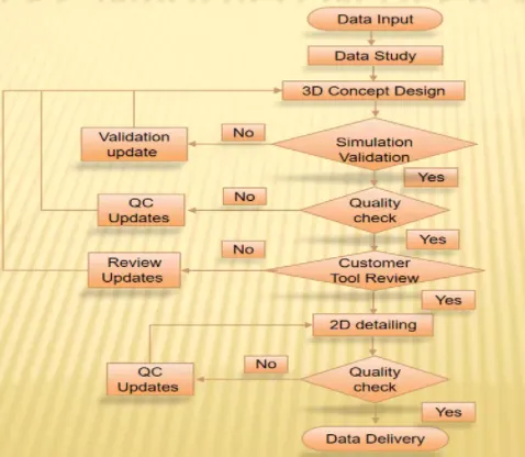
1.RFQ Received:
In BIW fixture design project begins. It starts with basic requirement or RFQ that we receive from customer. RFQ means request for quotation where in customer give his requirement specification etc. in form of some document or data to study or to work on information include such as technical offer, commercial offer, timeline of project Based on that we have processing to execute project.
2.1st specification discussion meeting:
In this the documents related technical offer, commercial offer, project execution, timeline required to complete the project are prepared. The time required to 3D design, analysis of design, drawing & detailing, manufacturing, assembly & commissioning etc. is considered. Then cost of all operation is considered. By considering these kinds of things the offer is prepared & submitted to customer. Below fig. show document that how technical offer is made.
3.Offer submission:
All the relevant details from the previous step is sent to the customer. All the techical drawings, detailed cost breakdown, project timeline, CAD files are shared with the customer.
4.PO/LOI:
Once we submitted offer customer will study the offer at the same time he will get offer from different supplier & vendor. He compares these technical offers & based on cost whichever suit best for his requirement. Then he will release LOI or PO with its terms & conditions as stated earlier.
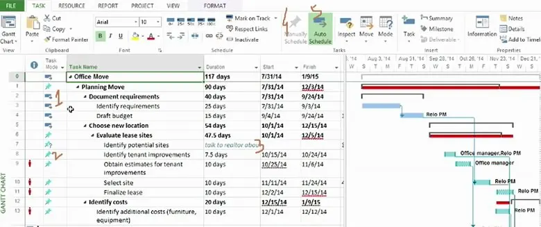
5.Schedule Preparation:
In project each activity depends on previous activity. So if previous activity has not completed on time it will cause delay in next activity date is fixed so that it will move further. Each activity has assigned specific time i.e. when activity is starting & when it is ending? So we have some back plan so that final date comes to close final delivery date. There need to be proper scheduling to be done to complete project in time. “On time delivery” is one of the major requirements from customer side also customer wants commitment must be follow in respect of time.
6.BOM Preparation:
BOM preparation is listing down of part list which includes bought out parts, vendor parts, and consumable items with qty. of each item. Through BOM preparation material budget will be fixed. B/O parts include motor, gear box, cylinder, pneumatic & hydraulic valves etc. Also vendor parts include all machined, fabricated parts etc. whereas consumable includes like oil, grease, glue, loctite etc. .
7.Design concept preparation:
Further step is to design a concept. A concept is based on all specification, received data from customer as 3D data of car panel, drawing, drawing std., design std., manufacturing std. After studying all data design concept is build.
8.Customer approval:
As design concept ready then it is send to customer for its approval. It is also known as design approval process (DAP) or customer approval process. In that customer will check that all his specification consider or not in specifications. Whether it is as per technical offer submitted then only he approves prepared concept. Some points will be raised by customer. These changes are updated to design team by project team. Design team again work on it some modification or changes are necessary to improve design like clamping need to be improved or this mechanism will work fine, sensor should be of this make. These changes are again updated to customer. Once he gave final approval we will move further for detailing & dwg. release.
9.Detailing & Dwg. release:
In detailing all assemblies broken down into its child parts. Parts of assembly are segregated into std. as well as manufactured. For std. parts own data sheet or specification sheet prepared to purchase it from catalogue. e.g. motor power, motor current rating, torque produced, shaft rpm which suit for our application. For vendor parts all detail should be provided on dwg. Like all dimension of part with tolerance, surface finish, surface treatment, hardness, welding note all should be mention on dwg. These dwgs are checked & released for manufacturing.
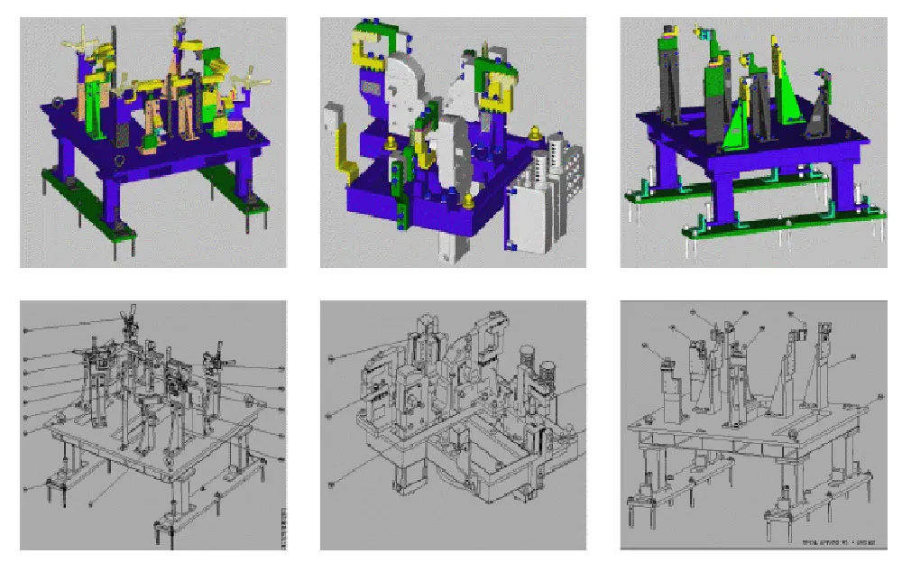
10.Manufacturing & B/O ordering:
Manufacturing department will receive all dwg to start manufacturing of items like mylar, blade, riser, base frame. Also purchase team will place order for B/O parts like motor, gearbox, cylinder & valves. As material get ready, QC team should inspect all part received is as per specification or not otherwise it will create issue later which will waste our time
11.Mechanical & electrical assembly:
After qc check, parts are available for assembly. A station is integration of all mechanical as well as electrical assembly. Assembly team will do all assembly as per dwg. All station are build as per layout Then again qc team should be involved for checking assembly as per final dwg., all coordinate dimension should be ok as per design data.
12.Internal trial & testing:
After approval of qc team, Internal trials & testing started. The first step involves putting assembly in fixture manually to check that it being fix properly, locating pin match with hole, clamping is ok, loading & unloading of part is easy. Also operating height is also checked, it is ergonomically correct. Then start taking trials on fixture for welding feasibility, gun approachability in fixture. Then go for online trial.
13Online training:
After successful of trial next step is online training. In online training has two mode manual & automated. In online trial system is run through control panel. All sensor, actuator, motor current & temperature, noise, all alarm, also safety should be tested. All process must be executed as per sequence also cycle time meet. In online training system run for certain cycle & actual production taken to ensure system run successfully.
14.Packaging:
After trial get successful, customer give approval to dispatch system. To dispatch whole system needs to disassemble station wise & pack properly. Delicate material should be packed properly otherwise there is chance of damage aesthetically or functionally during transportation. During packaging labeling, special handling instruction should be pasted on particular parts to convey message of taking care during handling & transportation.
15.Dispatch:
All material transported at customer site through trucks, container, and ships or by air.
16.Installations:
All system is assembled & installed at customer end as per layout approved initially in DAP. All station, robots, conveyor mounted as per distance specified in layout. Robot arm should be reachable to station, pick & drop point. It shouldn’t foul with other equipment. Also some adjustment should be provided for leveling purpose at robot conveyor base, station base frame like leveling stud to align with other equipment. Layout is always specified at the time of initial design stage & it has to be approved by customer.
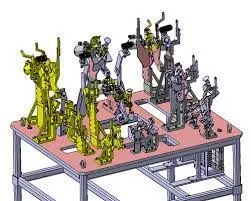
17.Trial & training at customer end:
Once installation is done trial start at customer end. So there will be production trial, online trial. Production trial is necessary because at the time of designing fixture, it also committed no. of unit that will be manufactured from that fixture also whether it is meeting quality, bench mark or not. Also in technical offer it is committed that there will be 100 units per 8hrs shift will manufactured from that fixture with weld quality. So during production trial fixture capability will be ensured. Once this goal is achieved then there will be training to operator, staff member, engineers to let them to understand how process is working?
18.Buy off meeting:
Once training is completed there is buy off meeting between customer & project team with discussion on if there other things need to be incorporated, anything missing that described in LOI/PO or offer submission. Then customer will raise point or sometimes customer wants modification that will lead to extra quotation, extra costing according work is done as per buy of meeting.
19.Final handover:
Once all points raised by customer will be closed then all will go for final handover. All data, technical manual, soft hard documents will submit to customer. These are main project activity.
2).Types of joining processes:
Joining includes welding, brazing, soldering, adhesive bonding of materials. They produce permanent joint between the parts to be assembled. They cannot be separated easily by application of forces. They are mainly used to assemble many parts to make a system.
Types;
- Riveting.
- Caulking.
- Bolting.
- Shrink fitting.
- Hemming and seaming.
1.Riveting:
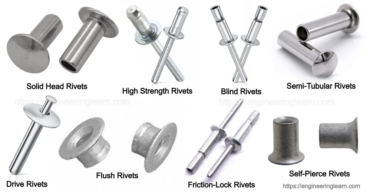
A rivet is a mechanical fastener with a plane unthreaded shaft that is inserted through holes to join two or more parts together. A permanently formed head at each end prevents the rivet from removal from the hole. The shaft prevents any radial movements of the components. it is used for thin metal plates.
2.Caulking:
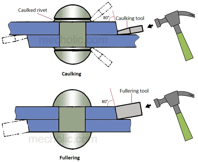
Caulking is the process of putting caulk to seal gaps and seams in pipe joints. It is done to make sure the pipe remains watertight or gas-tight. Caulking is integral for the joints. This is how water seams are tightened and fitted in construction piping.
3.Bolting:
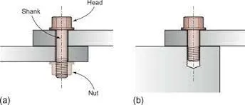
Bolting is a standard method of joining two pieces of metal together. It is a cost-effective and reliable way to join metals, requiring no extra processes such as welding or soldering. Bolts are often used in construction, manufacturing, and engineering applications, but they can also be used for other tasks, such as fastening furniture. This guide will look at the basics of bolting, the types of bolts available, and the process for bolting two pieces of metal together.
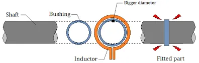
4.Shrink fitting:
Shrink fitting refers broadly to techniques in which thermal expansion and contraction effects are used to achieve an interference fit. Commonly, this involves the heating of the 'outer' part so that it undergoes thermal expansion. The two pieces can then be relatively easily fitted together.
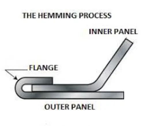
5.Hemming and seaming:
Hemming is a forming operation in which the edges of the sheet are folded or folded over another part in order to achieve a tight fit. Normally hemming operations are used to connect parts together, to improve the appearance of a part and to reinforce part edges.
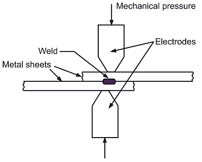
3).1.Resistance Welding & its application in the automotive sector:
Resistance welding is the joining of metals by applying pressure and passing current for a length of time through the metal area which is to be joined. The key advantage of resistance welding is that no other materials are needed to create the bond, which makes this process extremely cost effective.
The weld is made by conducting a strong current through metal combination to heat up & finally melts metal at localized points predetermined by the design of electrodes and or the work piece to be welded.
A force is always applied before, during & after application of current to confine the contact area at weld interface & in some workpiece to forge the wokpiece.
2.Resistance seam welding:
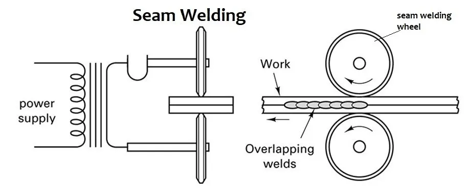
Resistance seam welding is a a continuous weld is produced by passing the work between rotating wheel-shaped electrodes, which exert the welding pressure and also conduct the welding current. It may be continuous or intermittent. It is used to make airtight joints.
In this process the rollers are contacted to the workpiece. The high current is passed through these rollers. Due to increase in temperature the interface surfaces will melt and form a weld joint. Now the rollers start rolling on the work plates. This will form a continuous weld joint.
The movement time of the weld and electrode is controlled to assure that the weld overlaps and the workpiece is not too hot.
Advantages
- It can produce airtight welds
- It is a fast welding process
- No flux or filler is required
Disadvantages
- Only straight or uniformly curved line welds are possible.
- Limited thickness of sheet can only be used.(Upto 3mm)
3.Resistance projection welding:
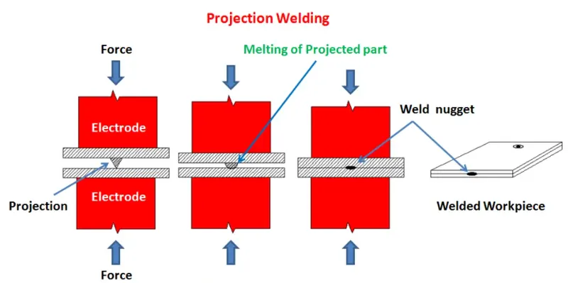
Projection welding is quite similar to as spot welding in operation. But in projection welding a dimple is produced on work pieces at the location where weld is desired.The work pieces are held between electrode and a large amount of current pass through it. A small amount of pressure is applied through electrode on welding plates. The current pass through dimple which melt down it and the pressure causes the dimple flatten and form a weld.
4.Resistance spot welding:
In this process, the parts to be joined are held firmly between two heavy electrodes, which are connected in the secondary circuit of the step-down transformers. The maximum resistance exists at the contact surface of the two parts being joined and high heat is developed.The spot size mainly depends on electrode size (4-7 mm).
Advantages
- Spot welding is quick and easy.
- No fluxes or filler metal is required to create a joints by spot welding
- Automation is feasible to reduce cycle time.
- Thin sheets can be easily spot welded.
Disadvantages
- It can create only localized joints.
- Cleanliness of the plates is very important to produce defect free joint.
5.Resistance Butt welding:
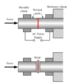
The heat is produced by the electric resistance at the butting surface by the flow of current and no arcing takes place between the surfaces being joined. A light pressure and a heavy current passed through the joint.When sufficient heat has been produced the two parts are suddenly pressed together and the current is simultaneously stopped. A thin film is produced around the joint which is subsequently removed to give a weld of this type.
Application
It is used for welding chains, rail ends, shaft axles etc.
4). Fusion welding and its application in automotive industry:
Fusion welding is a process that uses heat to join or fuse two or more materials by heating them to melting point. The process may or may not require the use a filler material. External application of pressure is not required for fusion welding processes, except for resistance welding, where substantial contact pressure is required during welding for sound joining.
1.Arc Welding
Shielded metal arc welding(SMAW)
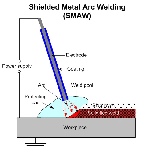
Shielded Metal Arc Welding (SMAW), also known as manual metal arc welding (MMA or MMAW), flux shielded arc welding or stick welding. It Suitable for welding both ferrous and non-ferrous materials in all positions. It uses a metallic consumable electrode of a proper composition for generating arc between itself and the parent work piece. The molten electrode metal fills the weld gap and joins the work pieces. The electrodes are coated with a shielding flux of a suitable composition. The flux melts together with the electrode metallic core, forming a gas and a slag, shielding the arc and the weld pool. The flux cleans the metal surface, supplies some alloying elements to the weld, protects the molten metal from oxidation and stabilizes the arc. The slag is removed after solidification.
The SMAW welding machine provides constant current (CC) using direct current (DC) or alternating current (AC). Direct current operates on different directions based on the polarity. Alternating current switches between directions.
Applications
- Construction
- Pipelines
- Shipbuilding
- Underwater welding
- Farm machinery manufacturing
Advantages
-
Simple, portable and inexpensive equipment.
-
Wide variety of metals, welding positions and electrodes are applicable.
-
Suitable for outdoor applications.
Disadvantages
-
The process is discontinuous due to limited length of the electrodes.
-
Weld may contain slag which requires cleaning.
-
Fumes may make the process control difficult.
2.Metal Inert gas(MIG) welding
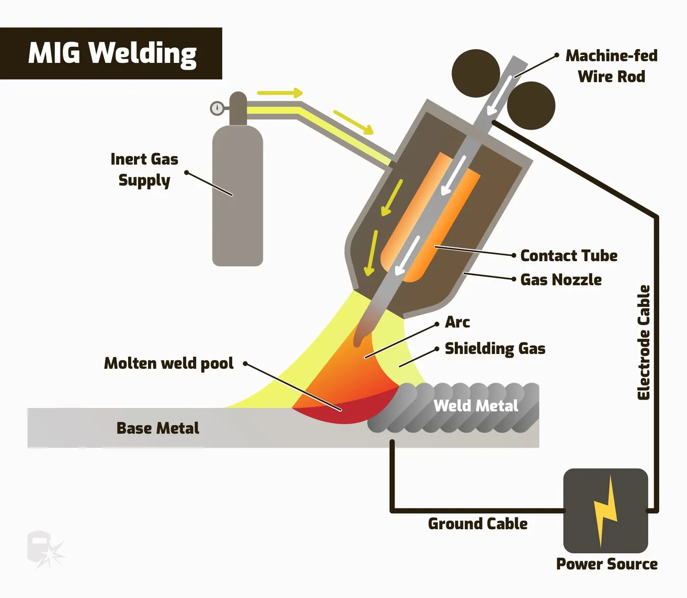
MIG welding is also known as Gas Metal Arc Welding (GMAW). MIG welding uses an electric arc between a consumable wire electrode and the workpiece leading them to melt and join. The shielding gas is used to protect the weld from airborne contaminants, or oxidation. It is easier to learn MIG welding and it produces welds that require little to no cleaning and finishing.
Applications
- MIG welding is most commonly used to repair cars, motorbikes, recreational vehicles etc.
- MIG welding is best suited for fabrication of sheet metal.
Advantages
- It can be used to weld thicker materials
- It has Greater deposition rates.
- It has shorter lead times
- The Production cost is low
Disadvantages
- Higher initial setup cost
- Less efficient where high duty cycle requirements are necessary
- Radiation effects are more severe
3.Tunsten Inert Gas welding(TIG)
t is also known as Gas Tungsten Arc Welding (GTAW). This arc process uses a non-consumable tungsten electrode to create the arc between the electrode and the base plate. An inert shielding gas is used to protect from oxidation or other atmospheric contamination. This process can be used on thin parts, and requires the consumable wire for filling the gap. The TIG welders require highly specialized training to ensure they achieve proper precision and accuracy.
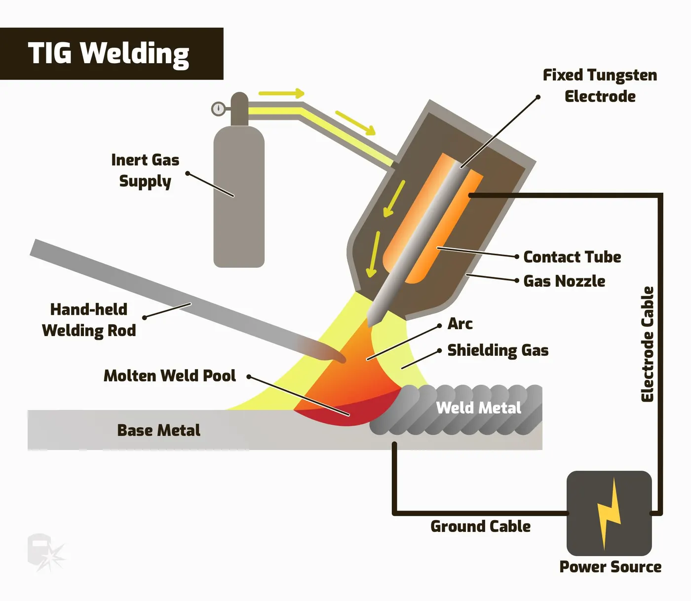
Applications
- In Aerospace industry to fuse the intricate airplane parts and the plane’s skin while still enhancing its much valued aesthetic value.
- Automobile Industry to produce corrosion resistant metal fusion.
- Industries use TIG welding on the thin workpieces, and also for nonferrous metals.
Advantages
- Tig welding is used to make rust-resistant metal fusion.
- High precision and strength weld can be made.
- TIG welding does not produce slag
- It can be performed in any welding position
Disadvantages
- It is a slow welding process
- High skilled labor is needed for TIG welding.
- Operation cost is much expensive
- Welders are exposed to high intensities of light.
4.Plasma Arc welding
Plasma arc welding is a liquid state welding process in which, the metal to metal joint forms in molten state. The hot ionized gases are known as Plasma. These hot ionized gases used to heating the work plates, and the joint is created due to fusion. This welding process is same as TIG welding process except plasma is used to weld the work pieces instead of arc. Filler material may or may not be used. The flux also prevents spatter and sparks while suppressing ultraviolet radiation and fumes.
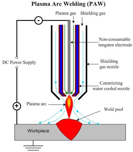
Applications
- This welding is used in marine and aerospace industries.
- It is used to weld pipes and tubes of stainless steel or titanium.
- It is mostly used in electronic industries.
- It is used to repair tools, die and mold.
Advantages
- High welding speed can be achieved
- It can be easily used to weld hard and thick work pieces.
- The distance between tool and work piece does not effects the arc formation.
- Low power consumption for same size weld.
- More stable arc produced by PAW method.
Disadvantages
- Higher equipment cost.
- Noisy operation.
- More radiation
- High maintenance cost.
5.Submerged arc welding
It is a joining process that involves the formation of an electric arc between a continuously fed electrode and the workpiece to be welded. A blanket of powdered flux surrounds and covers the arc and, when molten, provides electrical conduction between the metal to be joined and the electrode. The SAW process is usually automated.Material applications of SAW include carbon steels, low alloy steels, stainless steels, nickel-based alloys,etc
5).3-2-1 principle:
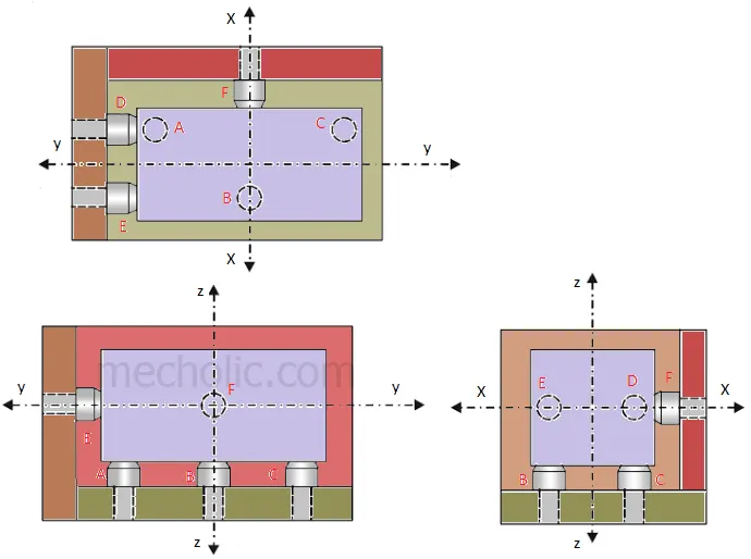
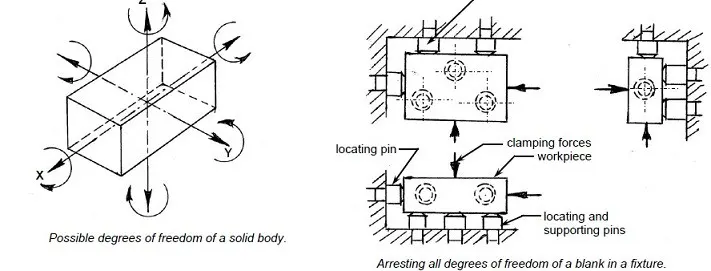
The 3-2-1 principle is the basic principle used in BIW fixture design. It is used to lock all six degree of freedom of the workpiece. It is a Component holding principle where three pins are located on any of the 1st principle plane(XY, YZ, ZX). And two pins are located on the 2nd plane which is perpendicular to the 1st plane, and at last one pin on the plane which is mutually perpendicular to the 1st and 2nd planes.By using this method Componet movement can be arrested in all six degrees of freedom.
6).Body plane system & its essential:
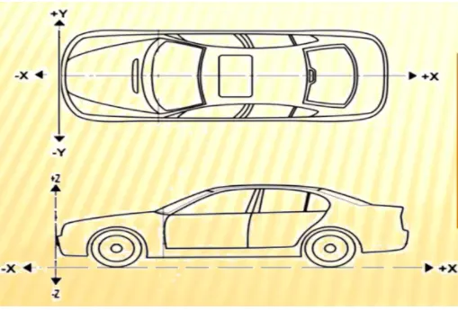
Body planes are the reference plane in an automotive car. These planes are used to define the GD & T of all car parts in a automotive domain.
Body planes are three mutually perpendicular imaginary planes. These are generally considered to be present at the driver position or sometimes at the engine location or at the front end of the car depending on the customer.
The measurements from the body planes to the parts are called as body line dimension.
These body planes are called as
- FOL Front “O” line.
- COL Centre “O” line
- BOL Body “O’ line
The measurement along FOL or X-axis is called as F/A Front aft.
The measurement along COL or Y-axis is called as C/C Cross car.
The measurement along BOL or Z-axis is called as U/DUP down.
In below figure origin is somewhere below driving sheet as it depends or changes from customer to customer. But axis system is commonly same.